Clinker Cooler Grate Pressure Imbalance and Red‑River Formation: Diagnostic Guide
Quick answer
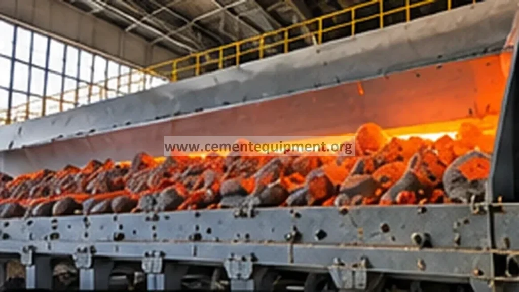
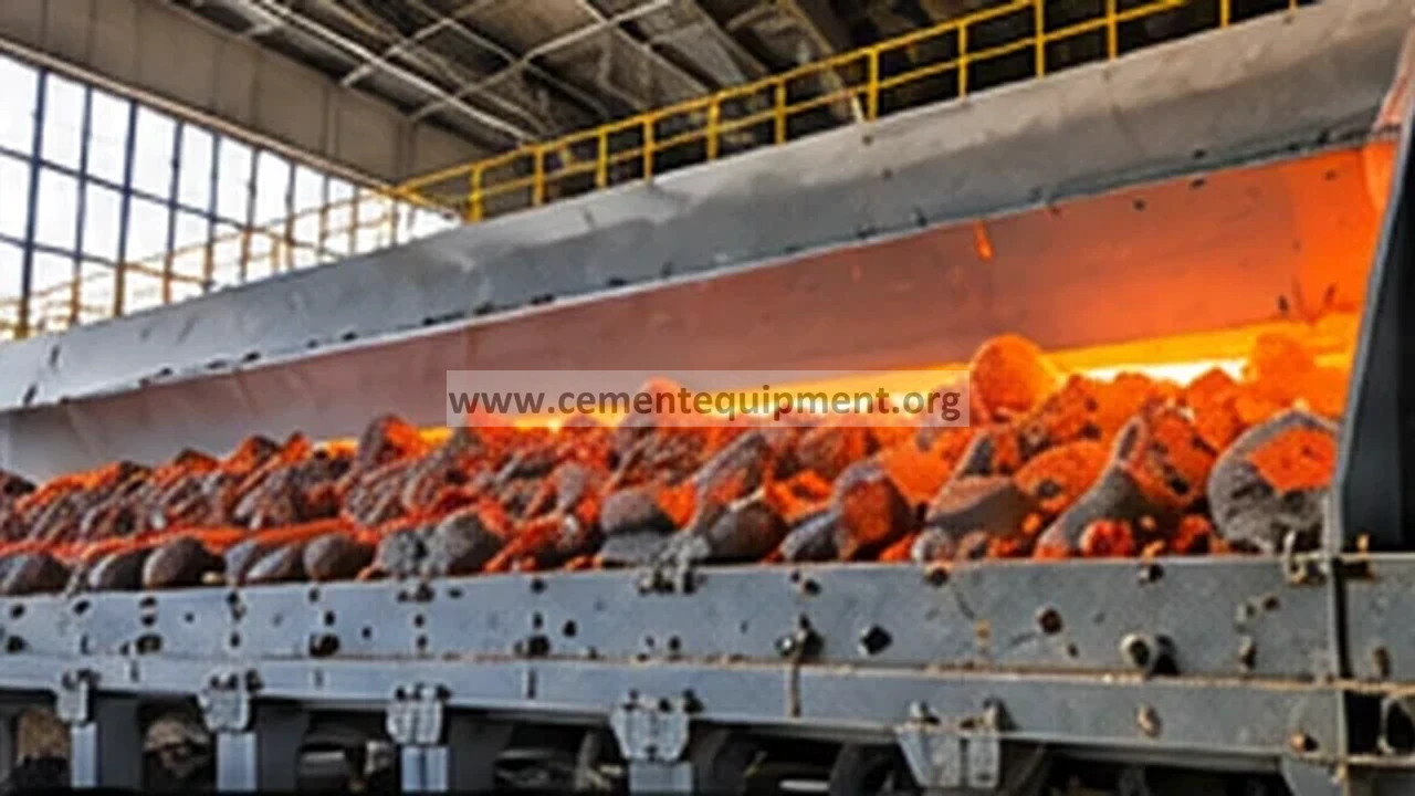
A red river is a localized stream of unusually hot clinker that can accompany nonuniform bed distribution or cooling-air delivery. It does not, by itself, establish a particular undergrate-pressure fault. Compare sector pressures, fan and damper status, clinker-bed condition, thermal observations and instrumentation against an approved operating baseline. Collect online evidence before shutdown; any internal inspection requires a planned shutdown, verified isolation, residual-heat and material-hazard controls. Authorize adjustments or repairs only after the cause is supported by evidence, then verify recovery under comparable stable operating conditions.
Problem / Job
Operators observe a red river, meaning a localized stream of hotter-than-surrounding clinker, alongside an apparent undergrate-pressure imbalance. This may indicate uneven clinker-bed distribution, local air maldistribution or a measurement problem; no single cause is established by the observation alone. Hot clinker can increase downstream thermal loading and equipment damage risk. The task is to correlate process evidence, determine the initiating mechanism and verify safe recovery.
Evidence
- Grate pressure‑balance alarm (high‑side vs. low‑side differential exceeds alarm set‑point).
- Available thermal observations or downstream clinker-temperature measurements indicate a localized hot-clinker streak; confirm instrument location, reliability and the timing of the observation.
- Increased fuel‑gas consumption recorded on the cooler’s energy monitor.
- Visual inspection reveals soot build‑up on several grate plates and partial blockage of air‑distribution nozzles.
- Control system logs indicate intermittent loss of primary air flow to the affected sector.
Decision
Proceed with a structured, seven‑step workflow that isolates the cooler, confirms the pressure‑balance fault, inspects and clears the grate, checks air‑distribution hardware, and validates performance after restart. If any step reveals damage beyond routine cleaning, schedule repair or replacement per OEM recommendations before returning to service.
Practical 7‑step workflow
- Plan safe access. Capture available online trends before shutdown. For physical access, use the site-approved shutdown and lockout/tagout procedure covering cooler drives, cooling-air fans, hydraulic and pneumatic systems, automatic starts, residual heat, hot clinker, dust and unstable stored material. Verify isolation and safe temperature and access conditions; obtain confined-space permits where applicable. Do not enter or open the cooler on the basis of this guide alone.
- Correlate process evidence. Compare alarm history, validated sector-pressure and airflow trends, fan and damper commands, clinker-bed distribution, feed conditions and available thermal observations by timestamp. A red river is not defined by a universal thermocouple reading.
- Measure differential pressure. Using calibrated pressure transducers, manually verify the high‑side and low‑side pressures at the grate inlet and outlet. Compare with the control‑system values; any discrepancy may indicate sensor drift.
- Visual and mechanical inspection. With the grate isolated, remove the protective grating panels in the affected sector. Inspect for:
- Soot, clinker dust, or foreign material accumulation that restricts gas flow.
- Deformed or cracked grate plates that could create uneven gaps.
- Damaged or clogged primary‑air nozzles.
Document findings with photographs.
- Correct confirmed defects. With the cooler cooled, isolated and cleared for safe access, remove verified deposits or repair damaged grate and air-distribution components using the approved site/OEM procedure. Control airborne dust and residual heat; do not use compressed-air cleaning or replace components solely on the basis of a pressure alarm. Document wear and clearances against applicable design criteria.
- Restore cooling-air controls. After authorized isolation release, verify fan, damper and sector-control availability, instrumentation and protective functions. Changes to air distribution require the approved operating envelope and change-control process; identical flow across all sectors is not a universal target.
- Restart and verify. Release isolation only under the approved permit and personnel-clearance process, restore safeguards and restart under site procedures. Trend validated sector pressures, cooling-air flow, clinker-bed condition, discharge temperature and alarms during a defined stable period at comparable throughput. Investigate any remaining hot streaks before accepting performance.
Diagnostic matrix
| Evidence | Likely direction | Next check |
|---|---|---|
| High‑side pressure > low‑side pressure alarm | Restricted flow on low‑side (blocked grate or nozzle) | Manually measure pressures at each side of the grate. |
| Localized hot-clinker streak accompanied by a change in sector pressure or air-flow trend | Possible clinker-bed segregation, air maldistribution, restriction or instrumentation error; not a confirmed nozzle fault | Compare bed distribution, sector fan/damper conditions and validated pressure measurements before authorizing intrusive inspection. |
| Increased fuel‑gas consumption | Cooler operating at lower efficiency due to uneven cooling | Compare current consumption with baseline data for the same production rate. |
| Soot build‑up on grate plates | Gradual fouling causing progressive pressure rise | Perform a thorough cleaning and re‑measure pressure differential. |
| Intermittent loss of primary‑air flow in control logs | Faulty air‑distribution valve or sensor | Test valve actuation and sensor calibration. |
| Cracked or warped grate plate observed | Mechanical deformation creating uneven gaps | Replace damaged plate and verify alignment. |
Verification and acceptance criteria
After corrective actions, the cooler must satisfy the following measurable conditions before full production is resumed:
- Pressure balance. Differential pressure across the grate must remain within the alarm set‑point for at least three consecutive cooling cycles. Record the measured values and compare with the control‑system reading.
- Thermal profile. Confirm that the localized hot-clinker streak has resolved using reliable thermal observations and approved plant or OEM acceptance criteria under comparable feed and cooler-loading conditions. Do not apply a universal temperature-difference limit.
- Energy performance. If specific energy consumption is used as supporting evidence, compare normalized, trustworthy plant measurements at comparable operating conditions. Do not treat an arbitrary percentage deviation as a cooler return-to-service requirement.
- Air‑flow balance. Primary‑air flow meters for each sector must read within the design range for the current clinker throughput. Any deviation should be investigated before restart.
- Mechanical integrity. All inspected grate plates, nozzles, and support structures must be free of cracks, excessive wear, or mis‑alignment. Documentation of the inspection should be filed according to the maintenance protocol.
Only when all criteria are met should the operator clear the alarm and return the cooler to normal load.
Common mistakes and repeat‑failure traps
- Skipping LOTO. Performing visual checks while the cooler is still pressurized can lead to injury and may mask the true pressure condition.
- Relying solely on alarm values. Sensors can drift; manual verification of pressure is essential before deciding on corrective action.
- Cleaning without inspecting nozzle health. Removing soot does not address a cracked or partially blocked nozzle, which will cause the same imbalance after restart.
- Replacing only the most obvious fouled plates. Pressure imbalance often results from a combination of minor fouling across several plates; a partial clean may leave the root cause untouched.
- Restarting before the system stabilizes. Immediate restart after a quick clean can cause the alarm to re‑trigger if the underlying airflow path has not been fully restored.
- Neglecting to update maintenance records. Failure to log the exact components cleaned or replaced makes future troubleshooting harder and can lead to repeated failures.
- Adjusting control‑system set‑points to silence alarms. This masks the problem and can cause equipment damage; always address the physical cause before considering set‑point changes.
Related Infinity guides
Build a stronger cement maintenance library
The Infinity for Cement Organization technical package contains 900+ technical files. It is a one-time $249.99 purchase, with instant download immediately after payment and lifetime updates forever at no additional cost.