
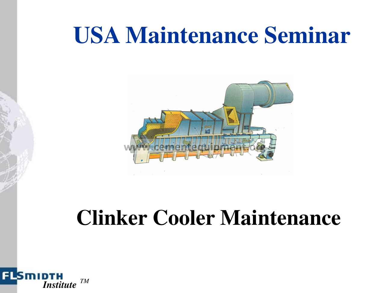
Uneven clinker-cooler undergrate pressure is a symptom, not a setting problem. Compare the affected compartment with adjacent zones at the same kiln rate: verify fan airflow/damper condition, inspect grate openings and undergrate chambers for clinker leakage or blockage, check bed depth and clinker size distribution, then correlate the pressure change with grate speed and discharge temperature. Do not force all compartments to the same pressure; each zone has its own design airflow and bed-resistance relationship.
Find why one cooler zone is high, low or unstable in pressure without destabilizing the whole cooler.
Use zone pressure, fan airflow/current, damper position, grate speed, bed depth, clinker size, grate condition and undergrate buildup.
Separate bed resistance, fan/air-delivery and mechanical grate leakage/blockage before changing setpoints.
Capture the whole cooler profile, not one pressure value
Record: undergrate pressure for every compartment; fan airflow/current and damper position; grate speed; kiln feed and clinker rate; cooler inlet/discharge temperature indications; clinker size distribution and appearance; visible red river or fine-clinker condition; and whether the pressure shift occurred suddenly or progressively.
The same pressure can mean different things at different kiln rates and clinker size distributions. Compare with a stable baseline at similar production.
1. Check whether the clinker bed changed
Undergrate pressure reflects resistance to cooling air through the clinker bed. A deeper or finer bed generally creates more resistance, while a coarse/open bed can reduce resistance. Compare grate speed, kiln output and clinker size. If the pressure rise coincides with fine, dusty clinker or a deeper bed, the fan may be healthy and simply working against higher process resistance.
2. Verify actual fan airflow and damper response
Check that the fan is running at the expected speed, inlet vane/damper follows command, and motor current or airflow indication is credible. Inspect ducting for blockage or leakage. A high pressure with falling airflow can indicate the fan is moving along its curve against increasing bed resistance; a low pressure with low airflow may indicate a fan/damper problem rather than a thin bed.
3. Inspect grate openings and air-distribution elements
Blocked grate slots, clinker fines packed into air passages or damaged air-distribution elements can create local high pressure and poor cooling. During a safe shutdown, map plugged or damaged grate areas across the compartment. Uneven plugging can produce local hot zones even when average compartment pressure looks acceptable.
4. Check for clinker leakage into the undergrate chamber
Broken or worn grate plates and seals can allow clinker to fall into the chamber below, obstructing air paths and creating abnormal pressure. Inspect undergrate buildup, compartment partitions and seal condition. Large accumulation may also interfere with moving cooler components. Correct the source of leakage before merely cleaning the chamber.
5. Correlate pressure with grate speed and bed-depth control
Many cooler controls use undergrate pressure as a bed-depth signal. If the pressure input is false or unstable, the grate-speed loop can chase the signal and make bed conditions worse. Verify the pressure transmitter and impulse path before retuning control. Compare actual clinker bed appearance with the instrument response.
6. Check clinker distribution across cooler width
An off-center kiln discharge or red-river condition can create a deep/hot bed on one side and a thin bed on the other. If the cooler has split air zones or multiple pressure points, compare left/right behavior. Mechanical air balancing alone will not correct a severely non-uniform clinker bed; kiln discharge and cooler transport conditions must also be stabilized.
7. Avoid over-airing a problematic zone
Increasing fan air can help only when the fan and bed can use it. Excessive air through fine clinker can fluidize the bed, reduce effective conveying friction and create unstable grate behavior. Use the cooler OEM operating envelope and fan curve. The objective is stable cooling and heat recovery, not the highest possible pressure or airflow.
Undergrate-pressure diagnostic matrix
| Observed pattern | Likely direction | Next check |
|---|---|---|
| High pressure + fine clinker + faster grate | High bed resistance | Clinker size, bed depth and kiln condition |
| High pressure + low airflow/current change | Restriction/plugging | Grate openings, undergrate chamber and fan curve |
| Low pressure + low fan airflow | Fan/damper/duct issue | Fan, damper, duct and instrument |
| One side hot while average pressure looks normal | Uneven bed/air distribution | Left/right bed, grate condition and clinker distribution |
| Pressure signal oscillates without visible bed change | Instrumentation/control issue | Transmitter, impulse line and loop response |
Common mistakes
- Trying to equalize all compartment pressures to one number.
- Increasing airflow before checking plugged or damaged grates.
- Retuning grate-speed control before verifying the pressure transmitter.
- Ignoring clinker size distribution and bed depth.
- Cleaning the undergrate chamber without repairing the leak path that filled it.
Return-to-service verification
After corrective work, stabilize kiln feed and cooler operation before judging the result. Acceptance means compartment pressures and airflow follow the cooler’s normal profile, grate speed is stable, no recurring undergrate buildup or abnormal hot zone appears, clinker discharge temperature remains acceptable for the downstream equipment, and fan current/damper response are consistent with the plant baseline.
Related Infinity technical guides
References
Clinker-cooler operating guidance identifies bed depth, clinker particle size, clinker temperature and cooling-air quantity as major influences on undergrate pressure. Final compartment setpoints and fan operating limits must follow the specific cooler design and fan curves.