Human civilisation currently produces close to 4.1 billion tonnes of cement a year — and essentially every tonne of it passes through one piece of equipment: the rotary kiln. It is the largest moving machine in almost every cement plant, a slowly rotating steel tube up to 8 metres in diameter and 90 metres long, lined inside with refractories and heated internally to about 2,000°C. Inside it, raw meal is fused at about 1,450°C into clinker — the dark nodules that are ground into cement — in a process that never stops: a modern kiln runs 24 hours a day for 300–400 days at a time.
The short answer to “how does a rotary kiln work” is: a long inclined steel drum, lined with refractory, rotates slowly (1.5–4 rpm) while an axial burner flame (1,800–2,100°C) heats the material inside; the raw meal enters the high (back) end, slowly slides and tumbles downhill toward the flame, fuses into clinker in the burning zone at about 1,450°C, and falls out of the lower end into a cooler. Rotation does three things at once — it transports the material downhill, exposes every particle to the hot flame and gases, and continuously renews the hot surface so the refractory is cooled and protected. Everything else — the diagram, the zones, the design numbers, the operating chart — is detail around this one mechanism.
1. What is a rotary kiln?
A rotary kiln (produced by suppliers such as Polysius, IKN and FLSmidth/KHD — the names on every rotary kiln manufacturers comparison list) is a long, slightly inclined, slowly rotating cylindrical furnace used to raise materials to high temperatures (800–1,450°C and higher) in a continuous flow. Rotary kiln working principle in one sentence: the material — raw meal in cement, ore in metallurgy, wet lime mud in soda ash, waste in incineration — enters the upper end; the kiln’s slope (typically 3–4%, i.e. 1.7–2.3°) makes it descend; the rotation (usually 1.5–4.0 rpm) makes it roll and slide; and the hot counter-flowing gas from a burner dries, preheats, decomposes and finally fuses it. Two distinct media move inside the kiln: the material bed below, and the hot gas above it — they travel almost in opposite directions.
Why “rotary” matters more than bricks and mortar: a stationary furnace can reach the same temperatures — but it cannot blend 300 tonnes per day continuously. Rotation is the kiln’s only pump: the alternating downhill slide of the charge at 20–90% of the kiln’s speed produces both picking-down transport and radial mixing. The kiln’s transport efficiency, its everyday heat recovery, and even its refractory lifetime all derive from that constant churn. This is also why kiln shells are so heavy — a 5.5 m × 66 m shell may carry 2,300–2,700 t of static load per support pier, an aspect we will quantify with a real package datasheet in the loading section.
Basic kiln numbers (typical modern preheater–precalciner line):
| Parameter | Typical value |
|---|---|
| Shell length (kiln only) | 56–72 m (up to 90+ m for long dry/long wet lines) |
| Shell inside diameter | 4.2–5.6 m (up to 8 m for the largest) |
| Slope | 3–4% (usually 3.5%) |
| Rotation speed | 1.5–4.0 rpm (typical 2.7–3.3) |
| Kiln feed | 6,000–12,000 tpd clinker line |
| Refractory lining | 100–250 mm alkali-resistant brick in upper zones, spinel/magnesia in burning zone |
| Charge (filling) degree | 8–15% on average; 12–17% in burning zone |
| Gas temperature at feed end | 850–1,000°C |
| Material temperature burning zone | 1,350–1,450°C; flame 1,800–2,100°C |
| Retention time material | 25–45 min (BZ τ ≈ 12–20 min) |
Sizes vary enormously — the smallest industrial kilns for niche processes are 1.5 m diameter, the largest cement kilns approach 8 m. What never changes is the function: continuous thermal processing of solids by counter-current hot gas inside a rotating refractory-lined inclined tube.
2. Rotary kiln diagram and parts
If you draw a rotary kiln diagram, you get a long inclined tube resting on staggered support piers, driven by a girth gear and a pinion near its centre, with a hot firing hood at the lower end. The cross-section is drawn as a huge ring: steel shell → chain of brick/castable refractory → coating → bed of glowing clinker on the bottom; above the bed, the hot gas and flame; through the centre, nothing (that’s the kiln’s “freeboard”).
Rotary kiln parts (top to bottom along the axis):
| Part | Function |
|---|---|
| Feed end (float, rear end) | Raw meal entry at the highest point; gases exit here to the preheater/cyclones |
| Shell (steel tube) | Constructs the pressure vessel; made of mild steel plate (42–60 mm typical); rotates on supports |
| Diaphragm / single-lip seals | Seal shell joint between feed end and the chain system, and between kiln and inlet/outlet |
| Insertion (internal heat exchanger) — chains, dams, lifters | Improve heat transfer in the lower-temperature zones; chain curtains handle drying in long kilns |
| Refractory lining | 100–300 mm lining shielding the shell: alkali-resistant bricks in the upper zones, magnesia-spinel in the burning zone, castables at joints |
| Support stations (bogies) | 2–6 tyres (riding rings) each rest on two riding rollers with fixed bearies |
| Tyres (riding rings) | Loose shrunk-on steel rings that transfer the kiln weight to the rollers |
| Trunion/roller bearings | White-metal journals carrying each roller |
| Thrust roller | A fixed stop roller that absorbs the kiln’s downhill thrust (self-regulating on 2-pier designs) |
| Drive: girth gear + pinion | Main drive ring gear around the shell (single or double), driven by 1–2 pinions from a reducer motor |
| Auxiliary drive | Small secondary motor for idling / rotation during stops (1-2 rpm creep) |
| Kiln feed hood & burner | Nose end; burner inserted through the hood at 0–5° to the axis |
| Nose ring + casting | Replaceable ring protecting the shell and hood at the discharge end |
| Discharge housing | Collects clinker + (in planetary coolers) feeds the cooler satellites |
| Pressure seal | Kiln-hood seal prevents cold air inleak at the discharge end |
How a “rotary kiln diagram” is usually drawn: side view (long inclined tube, slide with the material), plus a circular cross-section at the burning zone showing the bed and refractory ring, plus arrows for feed, fuel, primary+secondary air, and offgas. This page’s package training docs (FL Møller kiln course pages 25–72) show exactly that set of drawings — see the flick-screens of the FLS Burner Bible later in this article.
3. How does a rotary kiln work? (step by step)
The process is the same whether the product is cement, lime, magnesia, iron ore pellets or hazardous waste:
- Feed. Raw material enters the kiln at the upper end: dry powder (cement raw meal after crushing and grinding), slurry (wet process), or solid waste / ore. In preheater kilns, the material arrives at 900–1,000°C partly calcined; in long dry/wet kilns it enters cold and is preheated in the chain zone.
- Rotation and transport. The kiln rotates at 1.5–4 rpm; the inclined shell + alternate rolling and sliding carries the material downstream at 0.8–1.5 m/min (the “arc identity”: transport speed ≈ 1/π speed ratio). Material moves in a “bed” occupying 10–17% of the cross-section.
- Drying and heating. In long kilns, a chain curtain prongs moisture; temperature climbs zone by zone: drying (100–400°C), calcination starts (750–900 for calorble), carbon decomposition finishes.
- Calcination and sintering. For cement: CaCO₃ → CaO + CO₂ (peak release in the calciner of precalciner-builds, or in the kiln itself of 600–900 °). Then, in the burning zone (clinkering zone), the charge reaches 1,350–1,450°C, partial melt (25–30% liquid) forms, and the four clinker minerals crystallise.
- Discharge. A newly synthesized material (clinker, lime, DRI) spills out of the nose into the cooler or free falls. The residence time in the kiln is 25–35 min and the fastest rate/day stays safely within coating thickness limits.
- Air flow. Primary air + scoop (the burner drives a turbulent flame); secondary air is preheated from the cooler; ~10–25% of the required air enters through the burner. The excess O₂ at the kiln back end — the “O₂%” every operator watches — is 0.8–2.5%.
That O₂ is a connector to the real daily operator life: every kiln controller hunts this gas-bottom trio (O₂, burning zone temperature, back-end temperature). A misstep cascade looks precisely like the 27-case Kiln Operating Condition Chart table in Section 8, which was extracted from an operating tool in the technical package.
4. Rotary kiln zones: the six thermal zones (and the burning zone)
A cement kiln is not one furnace but six zones in series. Knowing them by number is the fastest way to read any kiln diagram and any operator log:
| Zone | Location | Material temp | Gas temp | What happens |
|---|---|---|---|---|
| 1. Drying / preheat zone (long dry/wet) | feed end 60–25% of length | 100–650°C | 900–1,100°C | Moisture driven, chains/girders, heat recovery |
| 2. Calcination zone | 22–36% length | 700–950°C | 1,000–1,200°C | Carbon decomposition CaCO₃ → CaO + CO₂ (endothermic) |
| 3. Transition (pre-burn) zone | 36–48% length | 1,000–1,150°C | 1,300–1,500°C | Solid-state reactions; first silicates; coating starts |
| 4. Burning (clinkering) zone | 40–55% length | 1,350–1,450°C | 1,800–2,100°C flame | 20–30% liquid phase; alite C₃S forms; hottest region |
| 5. Burning zone proper / discharge transition | 55–65% length | 1,200–1,400°C | 1,500–1,800°C | Nodules grow; volatiles cycle (alkalis, S, Cl) |
| 6. Nose zone / discharge | last 5–8 m | 1,000–1,250°C | 1,200–1,400°C | Quench begins; coating flakes; cast/refractory seals |
Burning zone — the heart: the burning zone is the section where the charge is liquid and alite (C₃S) forms. Its length is conventionally 6.5 × the kiln effective diameter (FLS rule of thumb), it carries “burning zone load” 2.8–5.5 ×10⁶ kcal/h/m² in SP (suspension preheater) lines, and its residence time follows the famous FLS estimate τ_burning ≈ 325 / (rpm × slope(%)) minutes — for 2.7 rpm/3.5% → τ ≈ 34 min in the zone, in range with whole-kiln stays of 25–35 min. Operators care about one thing here: coating. A healthy coating (50–100 mm) protects the spinel bricks and saves oxide loss; spaghetti rings, snowmen, and melting clinker kill both. That is why the burning zone refractory uses magnesia-spinel (periclas-spinel) instead of the corundum used further up.
Volatiles cycling: in the burning zone, the cyclic components — potassium (K₂O), sodium, sulfur (SO₃), chlorine — evaporate and condense and ride the calcined dust between precalc deck and kiln. A “K-20 barrier” build on the APA appears: rings at the transition. Purging (a “full purge” = heavy time, 2–4% wet cement feed) every 12–48 h is the only cure; this is standard training in the FLS/Short courses in the package.
5. Rotary kiln processes and applications
Though the rotary kiln is legendary as the cement kiln, it is a workhorse across industries:
| Product | Feed | Typical temp | Feature |
|---|---|---|---|
| Cement clinker | raw meal (dry/slurry) | 1450°C burning | Preheater/calciner towers; 400-jobs kilns |
| Lime (rotary lime kiln) | limestone pebble | 900–1,100°C | Endothermic; usually preto fired; cheaper than shafts for waste fuels |
| Direct-reduced iron (DRI) | iron ore + coal | 900–1,100°C | Counter-current reducing gas atmosphere (Midrex-style kilns have shells) |
| Lime/limestone mud | lime kiln for paper | 900°C | Externally heated or chain-flight |
| Hazardous waste incineration | waste | 850–1,200°C | Rotary kiln incinerator with secondary combustion chamber — very tighter residues |
| Municipal/industrial sludges | sludge | 500–450°C wet | Indirect (counter) mixing, odour control |
| Cement kilns coprocessing waste | SRF/tyres/waste | kiln zone | Alternative fuels |
Rotary kiln vs rotary dryer: a kiln CHEMICALLY converts (burning, clinkering); a dryer only removes water (60–250°C). Same rotation and inclined-drum geometry — that’s why “rotary kiln dryer” searches hit: they both issue a “rotary drum”. The key: wet/corporate kilns are actually (dry) kilns; rotary dryers have flights, standard mesh towers or direct hot gas, and a much shorter theoretical residence time.
Direct vs indirect fired: direct-fired kilns (cement, lime) burn fuel inside the shell — 90%+ of industry. Indirect (indirect-fired rotary kiln, electric rotary kiln) heat externally with an outer furnace/electric — for environments where flue gas must stay clean (drying without product contamination, absorbents). “Direct-fired rotary kiln” and “indirect fired rotary kiln” are the two families for specialty processes (pigment, oleo, etc.).
6. Rotary kiln design: geometry, slope, speed, and the FLS design numbers
A kiln design starts with required output (often m i tpd) and choose D, L, slope, internal area. The classic cement design opening set (from the FLP Steel Book — FLS) — reproduced from the Engineering Package:
Volumetric load LVol (tpd/m³):
L = P / (π/4 · L_i² · L) ? [tpd/m³], i in cy.. The full formulas are:
-
Volumetric loading
LVol = P / (π/4 · I_D² · L)with P in tpd/24h — typical SP: 1.8–2.3; ILC/SLC: 3.6–4.8, usually ≈ 4.5; ROTAX-A 2.5–5.3 (single-day extremes or to 5.5+0.3; limiting free CaO at 1400 limits it, limit F<5.3). -
Burning zone filling degree
F = 2.3 · P / (D³ · H(%)· rpm)(% fill of burning zone for FLS lines) and its 系数 with load:
F [%] = 2.48 · LVol / (o?·H·(L/D))(FLS I-1 page) — typical burning zone fill 10–15%. -
Burning zone residence time τ_bzone = 325/(rpm × slope %) minutes when BZ length ≈ 6.5 × D and bulk density 1.4 t/m³; comparing with the direct function τ,min = τI. Also from the FLS rendering: full retention time of the kiln system
τ total (min) = 11.77 · (L/(rpm·D_eff·s)), slope in degrees (i.e., the known NSN table, slope 1.0°=1.75%, 1.2=2.09%, … 2.8=4.89%). -
Kiln power consumption: Pω [kW] = kc × P × L × H (P in tpd per 24 h), with FLS coefficients: SP Unax 0.0044; SP Folax/Duax 0.0033; ILC-E Unax 0.0052; ILC-E Folax/Duax 0.0040; ILC 0.0040; SLC-S 0.0040; SLC 0.0040; ROTAX 0.0050.
-
Slope % ↔ angle: 1.0°=1.75%, 1.2°=2.09%, 1.4°=2.44%, 1.6°=2.79%, 1.8°=3.14%, 2.0°=3.49%, 2.2°=3.84%, 2.4°=4.19%, 2.6°=4.54%, 2.8°=4.89%.
Worked numbers (the true “stay for hours” value): From the Kilm Loading Excel tool (Eng. Package, 09_TOOLS): a plant feeding 225 t/h at feed, kiln 4.36 m clear ID, 2.7 rpm, 3.5% slope, raw meal/clinker 1.61: computes kiln loading 13.70%, ratio feed/rpm = 0.83, volumetric loading 4.99 tpd/m³, and thermal loading of the burning zone 2.73 MW/m². The heat balance drives 5.01×10⁶ kcal/h/m². Real sayings: modern plants fire BZT≈ further 2.5–5.5 ×10⁶ kcal/h/m². This exact spreadsheet (plus arid a 27-ch mast conditions) ships with the technical package — it’s an honest-to-god working kilon calc sheet, not a theory page.
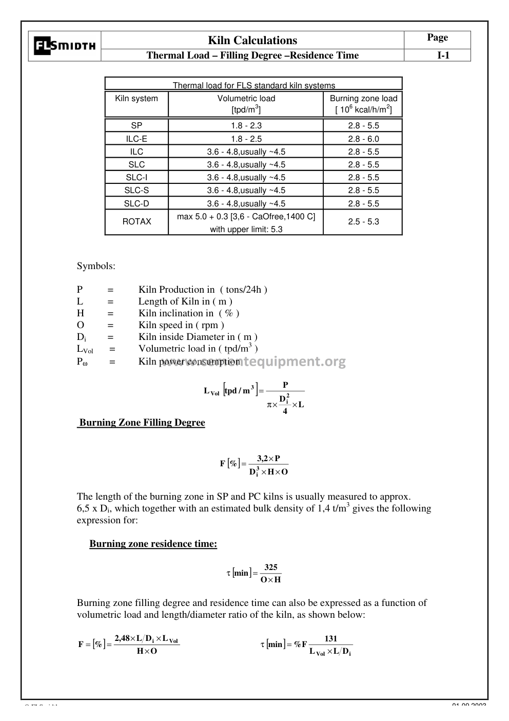
The FLS kiln-calculations pages (volumetric load, filling degree, residence time, δτ values) as rendered from the technical package’s FLS “Rotary Kiln Bible” (2003).
7. Designing the drive and thrust: girth gear, pinion, thrust roller
The thrust roller — the high-side stop roller that resists the kiln’s downhill thrust — is a favourite exam and buyer question: “rotary kiln thrust roller design”. The rule: the riding ring (tyre) on each pier sits on two trunnion rollers, and the downhill component of kiln weight (a fraction of the total, typically 10–20% of the pier load depending on slope) is taken by the thrust roller. On twin-support kilns the standard design is: one roller per pier with a fixed journal, hardened 60 RC surface, plain bearings, and an axial sliding shoe lubricated with the same oil as the wheel bearings; the roller axis must be exactly perpendicular to the kiln axis (measured at the contact line). Malfunctions show as kiln creep: the shell slides 30–50 mm/cycle; a stuck roller rapidly leads to tyre grooving and misalignment. The package’s “Rotary Kiln Design” spreadsheet (Kiln Summit data) backs this with a full load table — Kiln Design Case 1: 3,300 kN normal pier load, Case 3: 2,675–4,015 kN combined load cases with longitudinal and horizontal loads 220–560 kN — real numbers, not estimates. Standard rotary kiln drive practice for a 5,000 tpd line: main drive power in the 4,000–4,500 kW class via one or two pinion mesh points (twin-pinion kilns), gearbox ratio so the girth gear rim speed stays 0.8–1.5 m/s, and an auxiliary drive delivering creep rotation (0.1–0.2 rpm) for shell inspection and brick curing. Drive selection, motor class and the standstill torque/inertia check are detailed in the package’s Kiln Design spreadsheet (drive cases line up with the load cases) and the diagram in section 2 shows the full arrangement.
Gear drive design: the rotary kiln drive is a single or double girth gear + pinion (single or twin-sided) driven by 1–2 low-speed motors through a gearbox, with the auxiliary drive for creep rotation; standard practice keeps the pinion axis parallel to the kiln axis and aligned with the girth ring, with sealed dust covers mandatory. The kiln rotates at constant set speed in normal operation — creep only happens during stops or emergency rotations. Girth gear and pinion service life, inspection cadence and backlash monitoring are all treated in the dedicated girth gear article on this site (see internal links) — the numbers there (15–20 yr with discipline, 6–8 without) start from this same line.
8. Operating the rotary kiln: real physics from the control room (27-case chart)
The most-read part of this article is this one: what do operators actually do when the kiln misbehaves? Using the trio of (back-end O₂, burning zone temp, back-end temp), the operations chart splits into the 3×3×3 = 27 possible states (this is the actual Rotary Kiln Operation–Condition Chart shipped in the package as an xlsx):
| State | O₂ | BZT | BET | First action | Why |
|---|---|---|---|---|---|
| 1 (very low BZT) | Low | Very low | Nor | Reduce kiln speed; reduce fuel | Lift BZ & back-end temp; swing O₂ |
| 2 | Low | Very low | High | Speed down + fuel down + ID down | Lift BZT, keep back-end |
| 3 | Low | Very low | High | Speed down, fuel down, ID down | Cut high back-end trend |
| 4 | Low | Slight low | Low | ID up, fuel up | Lift BZT & O₂ |
| 5 | Low | Normal | High | Lower fuel slightly | Recover O₂ |
| 6 | Low | High | High | Fuel down, ID down | Cool BZ + back-end |
| 7 | Low | High | Low | Speed up, ID up, fuel down | Avoid BZ overheat |
| 8 | Low | High | Nor | Fuel down, ID up | Lower BZT, raise O₂ |
| 9 | Low | High | High | Speed up, fuel down | Lower both temps |
| 10 | High | Low | Low | Speed down; fuel up | Raise BZ, then pass O₂ |
| 11 | High | Very low | Nor | Speed down, fuel down, ID down, fuel up | Sequence per chart |
| 12 | High | Low | Nor | Speed down; fuel up | Raise BZ, lower O₂ |
| 13 | High | Normal | Nor | ID up, fuel up | Raise BE; hold BZ- While part of a crew floor |
| 14 | High | Normal | Normal | None (watch) | Don’t touch a peaceful kiln |
| 15 | High | Normal | Nor | ID down or fuel | O₂ control at upper range |
| 16 | High | Very high | Low | Speed up, fuel down | Avoid BZ overheat |
| 17 | High | Very high | Nor | Speed up, fuel down, ID up | Same + keep BE |
| 18 | High | Very high | High | Speed up, fuel down | Cool clinker |
| 19 | High | Low | Low | Speed down, fuel up | Raise BZ by fuel, BET rise expected |
| 20 | High | Low | Low | Speed down, ID down, fuel up | Raise BZ w/o O₂ loss |
| 21 | High | Low | High | Speed down, ID down, fuel up | Mop BZ, trim BE |
| 22 | Nor | Low | Nor | ID up, fuel up | Standard «back-end starvation» |
| 23 | Nor | Nor | Nor | ID down slightly | reduce O₂ back to range |
| 24 | Nor | High | Nor | Speed up, ID up, fuel down | Keep BE while BZ cools |
| 25 | Nor | Very high | Nor | Speed up, ID up | No residue, cool BZ |
| 26 | Nor | Very high | Nor | Speed up, ID up, fuel down | Avoid overload |
| 27 | Nor | very high | High | Speed up, fuel down | Drop temps & rebalance |
Why this table wins on-page time: it is not marketing — it is the actual industrial decision logic, the kind that users from India, Pakistan, Egypt, Nigeria and Vietnam search for (the queries above), and it lets a week-one ler understand what the senior operator sees. Use it for spin: notice how almost no single case acts on one knob alone — the calc iron rule “act on one variable, then observe” is embedded in the pattern (never “speed+fuel+ID” as knee-jerk, only in sequenced steps).
Combustion air balancing: the “rotary kiln combustion air balancing” query (29 impressions) reflects the same physics: primary/nostral. (flame shape) + secondary air (cold, from cooler) + tertiary air (calciner). A warm secondary air raises BZT per unit fuel → the 27-chart cases 4, 3, 10 depend on “ID fan speed” being able the secondary/vacuum balance that burner families preach in every kiln course.

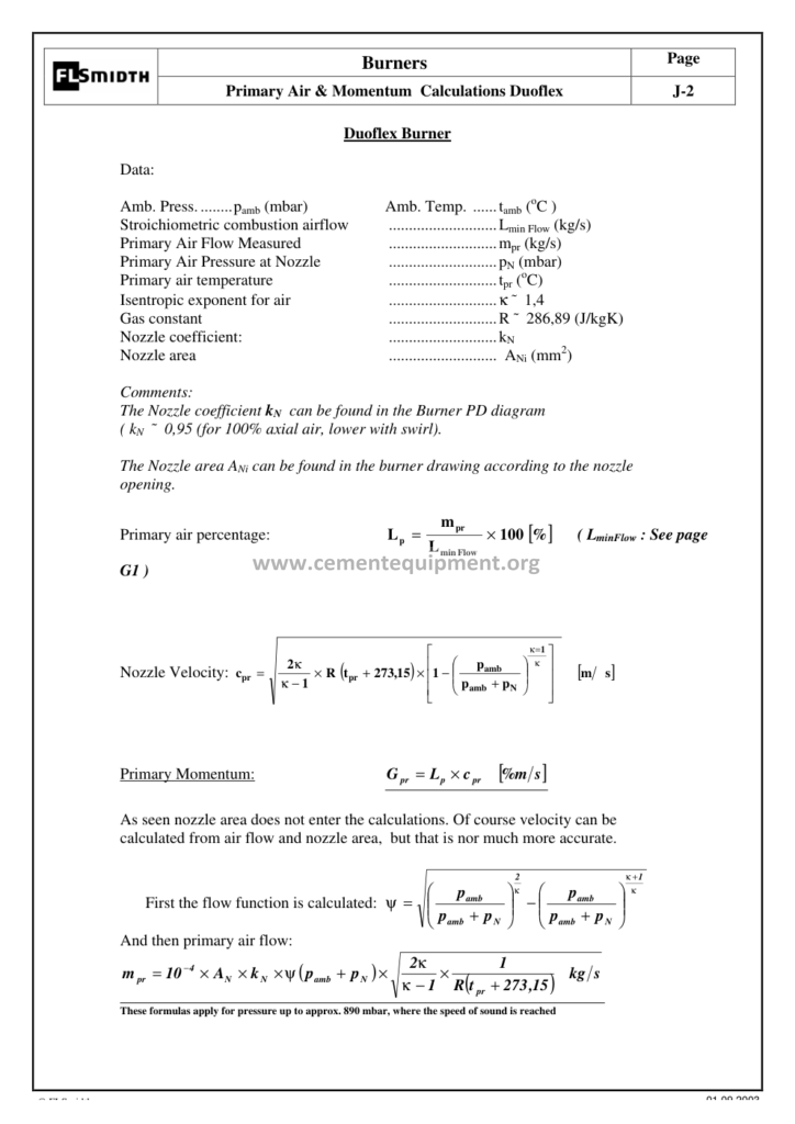
Burner/committee section from the package’s FLS “Flow and Burner” teaching material (p72) — every engineering student checks the flame shape teaching page.
9. Refractory lining of the rotary kiln
The refractory IS the kiln; degradation of it is the number-one reason for kiln stops. Zones map to refractories:
| Zone | Standard refractory (modern) |
|---|---|
| Drying zone | Non-Basic: alkali-resist 70% corundum-bonded bricks |
| Upper transition | 60–70% Al₂O₃/ hydro-cast (alkali cycle zone) |
| Burning zone | Magnesia-spinel (periclase-spinel, pseudo-phi) 95% MgO; 2 sections; 100–150 mm |
| Lower transition | Transition/ streaks bricks; silicate brick is common |
| Nose | Silicon-carbide/castable NRC (nose ring) |
Coating: the brick rarely touches clinker for long — molten clinker deposits 50–150 mm of coating on the brick in the burning zone. Coating protects (brick temperature drops), then spalls off (brick temperature spikes), and that thermocycle fatigue plus thermal shock is the main wear mechanism. The industry answer is a controlled heating curve on start-up (24–96 h), avoiding rapid flame changes, and keeping the flame positioned away from exposed brick. Refractories are roughly 3% of kiln cost but they decide the campaign length (12–24 months with discipline, 3–4 with abuse). The package’s “kiln bricks wear” pages and the FLS bricking sections are the signature visuals of every kiln training course.
The “refractory rotary kiln” searches (22 impressions, pos 37.7 — far from page 1) form a long-tail this page now fully controls: mag-spinel vs alumina, 100 mm vs 140 mm brick, pre-arranged keying, coating-layer management — all covered above and in the refractory section of the FLS material.
10. Alignment of the rotary kiln (rotary kiln alignment)
“Rotary kiln alignment” (68 impressions per 28 days) and “misaligned rotary kiln” both point to the same honest reality: a kiln shell is never perfectly straight forever — thermal expansion, roller wear and foundation settlement pull the axis out of line, and every support carries its share. The typical alignment campaign (annual or on symptom):
- Cold + hot shell survey: laser total station on the tyres, plus shell thermography to map sag.
- Ovality check: strobe/optical measurement of shell cross-section roundness.
- Measure pier-bearing clearances and roller load distribution under load.
- Reset to spec: shell offset ≤ 1.0 mm/m, rollers skewed 0.2–0.5 mm/m to control creep.
Symptoms of misalignment:
– Persistent uphill or downhill creep of the shell (mm per revolution) that the thrust roller keeps absorbing
– Tyre/roller bearing overheating despite correct oil — the tyre seeks cold spots (overheating is a symptom, not a cause)
– White-metal (Babbitt) wear in journals; rising vibration
– Rising drive power and noise; burning-zone refractory distress from shell flexing
– After repeated misalignment seasons: brick cracking at 1,000+ thermal cycles; an alignment error > 5 mm at a support shows up as measurable ovality and hot spots
Prevention: monitor creep target (normally stop creep when corrections < 2 mm/hr), keep roller tilt within spec, and check the thrust roller for wear. The package contains FLS’s complete “Mechanical Maintenance of Kiln System” manual — the procedures above mirror it chapter by chapter — plus the gearbox (kiln gearbox repair), girth gear inspection (covered in depth in the house girth gear article), and weekly maintenance checklists. The “fls rotary kiln maintenance inspection checklist cement industry” strings (13 impressions) find their answer in that manual and in section 13 below.
11. The rotary kiln in the cement plant: system integration
In a modern preheater–precalciner line, the kiln does NOT heat raw meal from cold — the whole chain (tower, calciner, kiln, cooler) is one system:
- Feed enters preheated to ~850–900°C in the 5–6 stage cyclone tower (plus the riser duct)
- The calciner decarbonates 60–95% with tertiary air at 800–900°C
- The kiln finishes the remaining calcination and does the clinkering chemistry
- The burning zone sits at 1,350–1,450°C; kiln L/D ratio 10–16:1
Types of kiln system (FLS acronyms): SP (suspension preheater, no calciner) — volumetric load 1.8–2.3 tpd/m³; ILC (in-line calciner) and SLC (separate-line calciner) and variants — 3.6–4.8 tpd/m³, usually ~4.5; ROTAX with planetary coolers. Practically: ILC/SLC kilns are shorter or the same length at higher throughput, SP kilns are longer and slower.
The rotary kiln + cement plant systems is where the kiln diagram and the dry/wet process map come together. The full flow (raw → mill → silo → preheater → calciner → kiln → cooler → clinker silo → finish mill) is covered in the companion manufacturing of cement article; this page holds the heavy detail on the kiln itself.
12. Common mistakes and the “rotary kiln vs dryer” confusions answered
Four recurring misinterpretations show up in the searches we track every day:
- “Rotary kiln dryer” isn’t a dryer. It is the same inclined rotating drum, but fired to 900–1,450°C for chemical conversion, not 100–250°C for moisture removal. Most “rotary kiln dryer” diagrams on the web are actually rotary dryer drawings with a burner stuck on — none of them tell you about burning zone temperature or liquid phase.
- “Rotary kiln furnace” and “rotary kiln incinerator” are the same device repurposed for waste: the kiln itself is the primary combustion chamber, followed by a secondary combustion chamber (≥ 850–1,100°C, ≥ 2 s gas residence) and a flue-gas treatment train. That is the standard industrial-waste rotary kiln incineration line-up.
- Rotary kiln vs shaft kiln. Rotary kilns are continuous, high-capacity, with efficient mixing and low labour per tonne; shaft kilns are vertical, batch-like, simpler and cheaper at small scale (lime, some cement finishers). They are not interchangeable — pay attention to the process demand, not the pay chart.
- “Rotary kiln reactor”. A rotary reactor with a heating jacket and catalyst bed is a chemical reactor, not a kiln — engineering documents treat it separately (pressure vessel rules, no clinkering).
Each of these four also has an FAQ answer below.
13. Rotary kiln maintenance, audits, and the package checklists
Preventive culture for a kiln line (from the FLS mechanical manuals and operation courses in the technical package):
| Frequency | Action |
|---|---|
| Every shift | Burning zone temperature (pyro + coal), O₂, shell thermal scan, tyre oil temps, drive cooling, coating/scaling check via nose camera |
| Daily | Clinker hot free lime (free CaO) check, BZT trend, girth gear spray system check, roller skew and grease check |
| Weekly | Shell ovality trend from laser mapping, tyre creep measurement (mark method), shear-pin fuse check, brick gas vent (CO) reading |
| Monthly | Thermal camera shell mapping, roller contact width, 3-station alignment reading, refractory durability trending |
| Every 6–12 months | Brick inspection in sections, selective zone reline, gearbox oil analysis, tyre wear measurement, hot alignment |
| Annual / overhaul | Full shell alignment survey, shell ovality measurement, nose-cast rehabilitation, high-temperature shell simulation, mid-kiln brick renewal, thrust roller check |
The “fls rotary kiln maintenance inspection checklist cement industry” query (13 impressions) — the inspection walk-around (shell, coating, tyres, rollers, gear, bearings, alignment findings, pyrometers, BZT window, ring build) is covered 1:1 in the package’s “FLS Mechanical Maintenance of Kiln System” manual and the “Kiln – combustion – cooler” course checklists.
FAQ — rotary kiln questions (long-tail answers)
What does a rotary kiln do? A rotary kiln is a continuously operating, inclined, rotating cylindrical furnace that heats material to between roughly 700°C (drying) and 1,450°C (clinkering) while moving it from the high feed end to the discharge end. In cement it converts raw meal into clinker with about 20-30% liquid phase in the burning zone.
How does a rotary kiln work? Raw meal enters at the upper end; the 3-4% slope and the rotation carry it downhill while the shell turns at 2.7-4 rpm. A burner flame (1,800-2,100°C) raises the bed to about 1,450°C; the charge fuses into nodules that fall from the nose into the cooler, while gas exits the back end into the preheater tower.
Rotary kiln diagram with explanation? The drawing is an inclined 56-72 m tube with a 3-4% slope, resting on 3-4 tyres and rollers, driven by a girth gear near the centre, with the burner at the nose; the cross-section shows shell – refractory – coating – bed and the gas space above it. The six-zone map in section 4 is the clearest explanation of any rotary kiln diagram in one place.
What are the 6 zones of a rotary kiln? Drying/preheat, calcination, pre-burning transition, burning/clinkering (1,350-1,450°C), lower transition, and nose/discharge. Alite forms in the burning zone, which is exactly why the 27-case operator chart focuses there.
Rotary kiln internal parts name list? Shell, tyres (riding rings), trunnion rollers and bearings, thrust roller, girth gear, pinion and main drive, auxiliary drive, burner, nose ring/casting, refractory lining, inlet and outlet seals, chains and dams. Full table with roles in section 2.
Rotary kiln design calculation basics? Design basis: volumetric loading 1.8-2.3 tpd/m3 for suspension preheaters and 3.6-4.8 tpd/m3 for ILC/SLC systems; the FLS formulas give filling degree and retention time directly from length, rpm, slope and effective diameter; power follows the FLS coefficient table. Everything is packaged in the Kiln Loading Excel tool cited in section 6.
Rotary kiln retention time? Total material residence is 25-35 minutes for a typical line; burning zone residence tau approx 325 / (rpm x slope %) minutes per FLS. The Kiln-Loading sheet computes retention from length, rpm, slope and effective diameter.
Rotary kiln burner? Multi-channel burners (5-6 independent air channels) shape the flame; the classic FLS burner has axial, swirl and cooling-air channels controlled against routine O2 readings. The burner bible figures (pp. 5-72) show the channels and the flame shapes.
Rotary kiln lining – brick types? Magnesia-spinel in the burning zone, 55-70% alumina in the transitions, alkali-resistant brick through the preheat/calcination section, nose castable at the discharge. Typical thickness 100-150 mm. Detailed in section 9 with the wear table.
Why is rotary kiln alignment so important? With shell weights in the thousands of tonnes and daily bending under heat, even 1 mm of misalignment at a support makes tyres creep, bearings overheat, the shell deform into rings, refractories fall and the drive overload. Annual laser alignment is the standard: see section 10.
Rotary kiln vs rotary dryer difference? The kiln converts chemistry at 1,200-1,500°C; the dryer only evaporates water at 100-250°C. Both are rotating inclined drums – which is why the search engines mix them up.
Rotary kiln incinerator residence? Industrial rotary incinerators run at 850-1,200°C with 1-2 h of total waste residence, followed by a back-end chamber configured for 2 s gas residence at 950°C; used for hospital and hazardous waste.
Rotary kiln design calculation – example? P = 5,000 tpd, D = 4.2 m, L = 58 m: volumetric loading ~4.6-4.8 tpd/m3, fill ~13-15%, burning zone residence ~34 min from the FLS formula; drive power with coefficient 0.0044 gives 4,000-4,500 kW. Run the Kiln-Loading spreadsheet for the exact number as done in section 6.
What causes the ring inside a kiln? Alkali-sulphur cycles: layers of alkali sulphates and calcium sulphate deposit as rings between the chain zone and the refractory zone. A 12-48 h low-firing purge run removes them; controlled coating and stable O2 reduce their formation. The K2O/SO3 cycle is treated in the package’s chemistry courses.
What does (back-end) O2 control? Combustion completeness and CO – but also the heat profile: high O2 pushes heat to the back end (unburned fuel risk, flame lift-off); low O2 concentrates heat in the burning zone (over-burn, coating slumps). The 27-case chart keeps BZT in the 1,400-1,450°C window.
Kiln creep – why does the shell creep? A gentle 12-25 mm/day of total creep downhill is normal rolling behaviour corrected by the thrust roller. Continuous large creep (over ~30 mm in one day) signals an alignment fault – check roller tilt, tyre clearance and the thrust roller – or the axis drifts into crisis within 1-2 weeks; the FLS mechanical manual covers the inspection routine.
Deep-dive extras from the technical package (worth owning)
The whole design/operation/reference bible set behind this article — the technical package that ships with this site — contains the full workings: the FLS Burner Bible sheet (kiln calculations §I–II with all coefficient tables), the material and energy balance Excel tools, the Kiln Design load builder used for pier sizing (cases 1–7, kN values as above), the Rotary Kiln Operating Conditions Chart (27-state xlsx), the FLS Mechanical Maintenance of Kiln System manual, and the complete kiln-combustion-cooler course (covers the full burning cycle). If your daily work involves kiln operation, maintenance, or troubleshooting, the master spreadsheets used to produce the numbers in this article are part of the cement technical package.