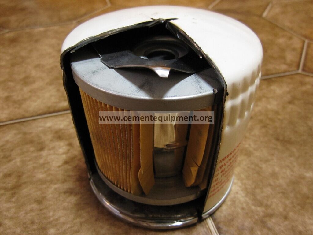
Lubrication oil filter bypass valve diagnosis
Use differential pressure, bypass indication, oil temperature, system flow and cleanliness trends together to determine whether oil is actually passing through the filter element. The featured cutaway illustrates the bypass mechanism; actual cement-plant filter housings and valve arrangements vary by OEM.
Quick answer
A lubrication filter bypass valve stuck open can make differential pressure look low while contaminated oil circulates around the filter. Diagnose filter inlet/outlet pressure, bypass indicator or valve condition, oil temperature/viscosity, element condition and oil cleanliness. Low filter DP is only reassuring if the oil is actually flowing through the element.
Problem / job
Filter DP remains unexpectedly low, oil cleanliness worsens or filter elements appear unusually clean despite contamination evidence.
Evidence
Capture filter DP, bypass indication, oil temperature, pump pressure, particle count, filter history and recent maintenance.
Decision
Separate genuine low resistance from open bypass, low flow, bad DP instrumentation and incorrect filter installation.
Seven-step workflow
- Verify DP measurement and pressure taps/instrumentation.
- Check oil flow/pump condition because low flow naturally produces low DP.
- Review bypass indicator and valve position/function under the equipment maintenance procedure.
- Inspect whether the correct filter element is installed and seated.
- Compare oil cleanliness/particle trend; worsening cleanliness with low DP strongly supports bypass or filtration failure.
- Check oil temperature/viscosity, especially during cold start when bypass may legitimately open temporarily.
- After repair, verify normal DP behavior and improving oil cleanliness.
Decision table
Diagnostic decision matrix
| Evidence | Likely direction | Next check |
|---|---|---|
| Low DP plus rising particle count | Bypass/filtration failure | Bypass valve and element |
| Low DP plus low oil flow | System flow problem | Pump and valves |
| Bypass indication active when oil hot | Stuck/open bypass or wrong element | Valve and filter specification |
| DP signal implausible compared with gauges | Instrumentation issue | DP transmitter/taps |
Acceptance criteria
Accept the lubrication system when oil flows through the intended filter path, bypass operation matches the OEM design, DP is plausible for temperature/flow and oil cleanliness stabilizes or improves.
How a stuck-open bypass appears in operation
The most dangerous symptom is a lubrication system that looks healthy on pressure but gradually loses oil cleanliness. A permanently open bypass can let the pump maintain normal header pressure while a large part of the flow avoids the filter element. Typical clues are unexpectedly low filter differential pressure, recurring high particle counts, rapid darkening of the oil, debris returning after a filter change, or bearings and gears showing contamination-related distress even though the filter element itself looks unusually clean.
Do not use one indication alone. Differential pressure depends on oil viscosity, temperature and flow. During a cold start it may be high enough for a correctly designed bypass to open temporarily. Once the oil reaches normal operating temperature, the bypass should return to its intended state and the filter differential pressure should become consistent with the established baseline. A bypass indication that remains active with warm oil and normal flow deserves immediate investigation.
Measurements to capture before dismantling
- Oil temperature at the filter inlet and, where available, at the reservoir return.
- Filter inlet pressure, outlet pressure and calculated differential pressure.
- Main lubrication header pressure and pump running status.
- Bypass indicator position or electrical status if the housing includes one.
- Recent particle-count or oil-analysis trend, not only the latest sample.
- Filter element part number, micron rating, installation date and last change reason.
- Any recent maintenance on the filter housing, bypass spring, seals, pressure taps or transmitter.
Compare these values with a known healthy operating period under similar oil temperature and equipment load. Trend comparison is more useful than an isolated number because filter differential pressure naturally changes as viscosity and flow change.
Likely causes and how to separate them
| Condition | Evidence pattern | Diagnostic direction |
|---|---|---|
| Bypass valve mechanically stuck open | Low DP, normal system flow, worsening cleanliness | Inspect bypass piston or poppet, spring and contamination around the valve seat |
| Incorrect or poorly seated element | Low DP after recent filter service | Confirm element specification, seals and installation orientation |
| Low system flow | Low DP together with weak pump flow or low header pressure | Check pump condition, suction restriction and control valves before blaming the filter |
| DP instrument or pressure tap fault | Transmitter reading disagrees with local gauges | Verify taps are clear and compare with an independent pressure measurement |
| Cold, high-viscosity oil | High DP and bypass indication only during start-up | Check warm-up behavior and oil grade against OEM requirements |
| Filter housing internal leakage | Clean element but persistent contamination | Inspect seals, internal standpipe and housing condition |
Inspection sequence after safe isolation
Follow the plant lockout and lubrication-system isolation procedure before opening the filter housing. Confirm stored pressure is released. Remove the element carefully so the as-found condition is preserved. Check for incorrect seating, damaged seals, collapsed media, bypass marks, metallic debris and evidence that oil has been flowing around rather than through the element. Inspect the bypass valve for free movement and contamination around its guide and seat. If the valve uses a spring, compare its condition and installation with the OEM drawing rather than stretching, shimming or substituting it in the field.
Cleanliness during reassembly is critical. A repaired bypass mechanism installed with dirty tools or exposed components can immediately reintroduce the contamination the filter is intended to control.
Verification after correction
- Install the correct filter element and seals.
- Restore the lubrication system and check for leakage.
- Record oil temperature, inlet pressure, outlet pressure and differential pressure.
- Confirm bypass indication returns to the expected state after warm-up.
- Verify system flow and header pressure remain normal.
- Take a baseline oil-cleanliness sample and compare it with the previous trend.
- Recheck the trend after sufficient operating time to confirm contamination is no longer recirculating.
The repair is proven only when the filter path is confirmed, differential pressure behaves logically with temperature and flow, and oil cleanliness stabilizes or improves. A normal-looking pressure gauge by itself is not enough evidence.
Common mistakes
Do not interpret low filter differential pressure as automatically good. Do not replace the pump simply because the filter DP is low. Do not use a higher bypass spring setting to hide a plugging problem. Do not install a substitute element without checking micron rating, collapse strength, flow direction and sealing dimensions. Do not clear pressure taps and then reuse the old transmitter reading without verifying it. Finally, do not return critical gearboxes, mills, kilns or hydraulic systems to unrestricted operation when oil-analysis evidence still shows uncontrolled contamination.
Build a stronger cement maintenance library
The Infinity for Cement Organization technical package contains 900+ technical files. It is a one-time $249.99 purchase, with instant download immediately after payment and lifetime updates forever at no additional cost.