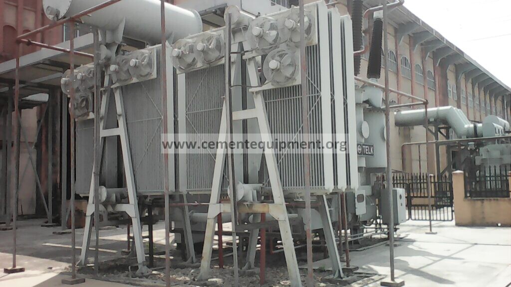
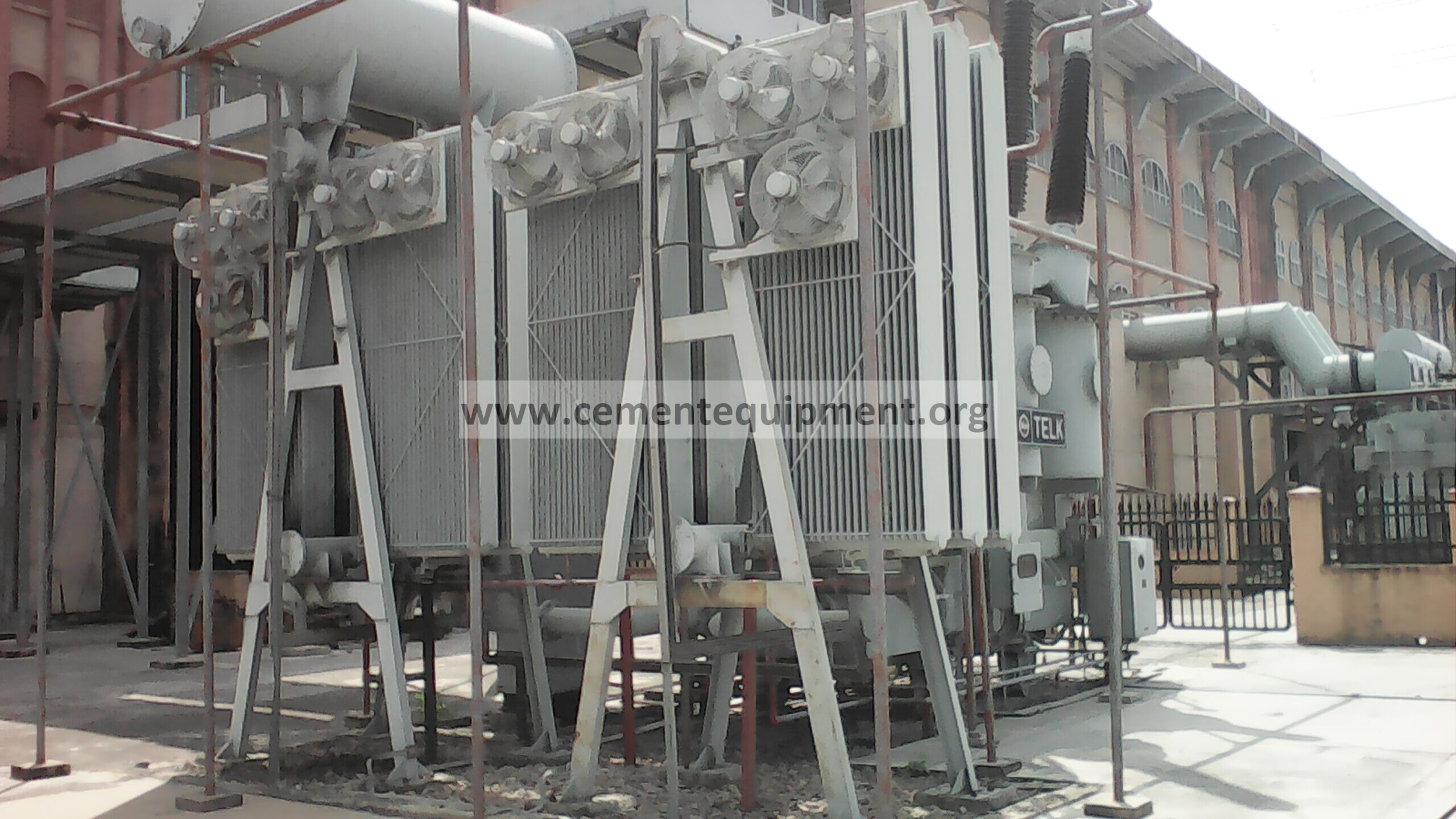
Transformer oil-temperature diagnosis under normal electrical load
When transformer oil temperature rises without an obvious load increase, diagnose the temperature rise above ambient together with cooling-system operation, oil circulation, three-phase load quality and measurement accuracy before assuming an internal transformer fault.
Quick answer
A transformer whose oil temperature rises while electrical load remains normal should be checked for cooling-system degradation, oil-level or circulation problems, abnormal losses, measurement error and changed ambient conditions before the transformer itself is blamed. Correlate top-oil temperature, winding-temperature indication, load current, ambient temperature, fan/pump status, radiator temperatures, oil level and recent maintenance. A normal kVA load does not guarantee normal internal losses if voltage imbalance, harmonics, contact resistance or cooling performance changed.
Problem / job
Top-oil or winding temperature trends higher than the established baseline although plant load appears unchanged.
Evidence
Capture three-phase load, ambient temperature, oil/winding temperature, fan and pump states, radiator temperature pattern, oil level, alarms and recent maintenance.
Decision
Separate cooling loss and measurement error from abnormal electrical losses, oil-circulation problems and genuine transformer deterioration.
Field evidence to collect before changing settings
Build one comparison snapshot before resetting alarms, changing cooling controls or altering transformer loading. Record ambient temperature near the transformer, top-oil and winding-temperature indications, phase currents and voltages, cooling-stage command and actual fan or pump operation, oil level, radiator temperature pattern, recent alarms and any maintenance that touched cooling circuits, sensors, tap-changer equipment or cable connections. Where site procedures allow, compare the same measurements with a known healthy period at a similar ambient condition and load.
- Cooling evidence: verify that every commanded fan and pump physically operates and that radiator airflow or oil circulation is not obstructed.
- Temperature evidence: compare oil temperature rise above ambient and check whether independent approved measurement agrees with the installed indication.
- Electrical evidence: compare phase currents, voltage balance and available harmonic or power-quality trends rather than relying only on total kVA.
- Oil-circuit evidence: check oil level, leakage history, radiator valve position and whether one radiator bank behaves differently from the others.
- Condition evidence: review oil-test, dissolved-gas, thermography and maintenance trends when cooling and instrumentation checks do not explain the rise.
This evidence sequence prevents a common maintenance error: treating a high temperature indication as proof of one failure mode. A transformer can run hotter because heat rejection deteriorated, internal losses increased, the measurement shifted or the surrounding condition changed. The corrective action should follow the evidence pattern, not the alarm alone.
As-found evidence capture
Compare the temperature rise above ambient, not only the absolute oil temperature. Record load current on all phases, transformer voltage, cooling stage status, fan/pump operation, oil level and the timing of the rise. Compare with historical data at similar ambient temperature and load.
High-voltage equipment must be investigated under the plant electrical-safety program by qualified personnel. Do not open, bypass or work on energized transformer compartments to chase a temperature alarm.
Seven-step diagnostic workflow
1. Verify the temperature indication
Cross-check the top-oil/winding indication with another approved measurement where practical. Inspect sensor wiring, capillary systems or transmitter scaling. A shifted sensor can create a false trend.
2. Check cooling fans and pumps
Confirm every commanded fan/pump actually runs, rotates correctly and delivers expected airflow or oil circulation. A contactor can show ON while a failed motor, blocked fan or incorrect rotation reduces cooling.
3. Compare radiator temperatures
Look for radiator banks or sections that remain unusually cool while the tank is hot, which can indicate closed valves, poor oil circulation or blocked passages. Dirty external fins can also reduce heat transfer.
4. Verify oil level and leakage history
Low oil level or trapped gas can reduce effective cooling and expose internal components. Review sight level, alarms and any recent leak repair or oil work using the manufacturer’s procedure.
5. Check electrical load quality
Review phase balance, voltage, power factor and harmonic information where available. Additional harmonic or unbalanced-current losses can raise temperature even when total kVA appears normal.
6. Review contacts, tap changer and internal-condition evidence
If cooling and measurement are normal, review dissolved-gas analysis, oil tests, thermography and tap-changer/contact history according to the transformer maintenance program. Abnormal contact resistance or internal deterioration can create excess heat.
7. Verify the correction against ambient and load
After restoring cooling or correcting the identified issue, trend temperature through comparable load and ambient conditions. Confirm the rise above ambient returns toward the historical baseline without alarms.
Evidence-to-decision table
| Evidence | Likely direction | Next check |
|---|---|---|
| High oil temperature with one cooling stage inactive | Cooling-system fault | Fans, pumps, controls, radiator airflow |
| Tank hot but one radiator bank cool | Poor oil circulation/closed path | Valves and radiator circuit |
| Temperature indication high but independent check normal | Sensor/instrument issue | Temperature device and scaling |
| Temperature rises with phase/current imbalance or harmonics | Additional electrical losses | Power-quality and connection review |
| Cooling normal but oil/DGA trend abnormal | Possible internal transformer issue | Engineering/OEM condition assessment |
Return-to-service acceptance criteria
Accept the transformer condition when cooling stages operate correctly, oil level and circulation are normal, temperature indication is verified, phase/load quality is acceptable and the temperature rise above ambient stays within the transformer/OEM and plant limits at representative load.
Common mistakes
Do not compare oil temperature without ambient temperature. Do not assume an ON indication proves the fan or pump is effective. Do not raise alarm limits to hide a new temperature trend. Do not open energized transformer enclosures for troubleshooting. Finally, use the transformer’s specific cooling class and OEM limits rather than generic temperature numbers.
Related Infinity guides
Electrical Transformers, Motors & Distribution provides broader plant electrical-maintenance context.
Build a stronger cement maintenance library
The Infinity for Cement Organization technical package contains 900+ technical files for cement professionals. It is a one-time $249.99 purchase, with instant download immediately after payment and lifetime updates forever at no additional cost.