Quick engineering answer
Kiln-shell scanner commissioning must prove three things: the thermal map is geometrically aligned with the real kiln, temperatures are credible against independent references, and alarm zones/outputs reach the operator correctly. A colorful thermal image alone is not acceptance; geometry, emissivity, shadow zones and alarm logic must all be verified.
What Kiln Shell Scanner Commissioning Must Prove
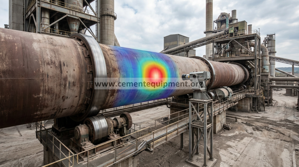
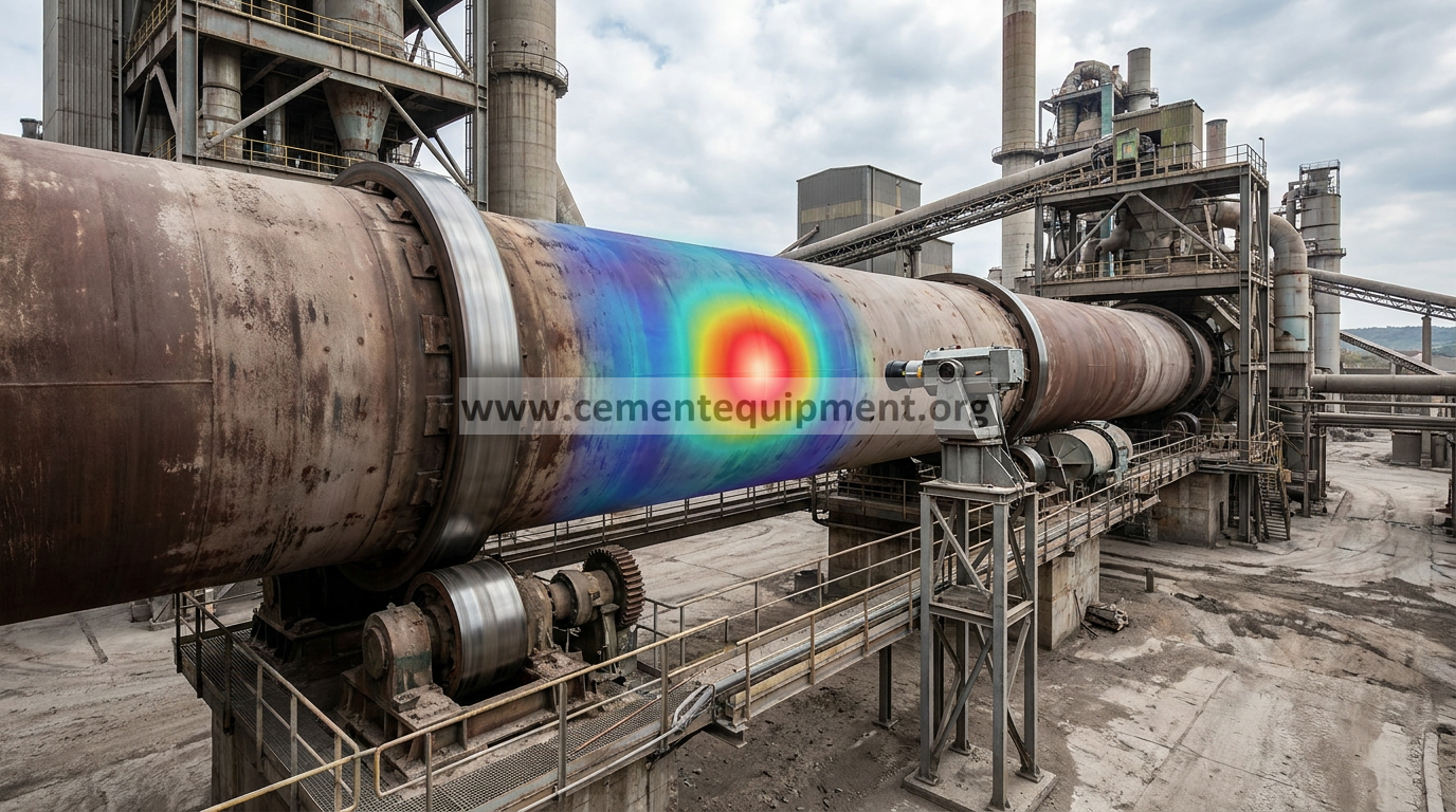
A kiln shell scanner is not commissioned simply because it displays a thermal image. The system must map the rotating shell to the correct axial and circumferential positions, measure shell temperature credibly, identify known physical features, handle shadow zones and transmit alarm/status information correctly to the operator interface or DCS.
Current commercial kiln-shell systems from Fuller, Thermoteknix and Fluke Process Instruments are designed for continuous thermal mapping and hot-spot detection. Their capabilities differ, but the practical commissioning logic is similar: geometry first, measurement validation second, alarm validation third, then a baseline under stable kiln operation.
Kiln length, scanner position, tyres, rollers and shadow zones.
Confirm the thermal image matches real shell landmarks.
Cross-check temperature against an independent reference.
Test alarm zones, outputs and operator response end-to-end.
Step 1 — Validate Scanner Geometry and Position Mapping
Enter the actual kiln dimensions and the scanner’s physical position using the vendor’s configuration method. Confirm the displayed tyre positions, support locations and shell zones against field landmarks. Systems that compensate for kiln movement or maintain position tracking still need a correct starting geometry.
- Confirm total monitored kiln length and excluded sections.
- Check scanner line-of-sight to the shell over the full visible length.
- Identify shadow zones caused by tyres, piers, guards, ducts or civil structures.
- Verify the displayed axial location of at least two unmistakable physical landmarks.
- Check encoder or synchronization input where the system uses kiln rotation position.
- Document any permanently hidden shell areas that require separate pyrometer or field inspection.
Step 2 — Validate Temperature Measurement
Infrared temperature depends on surface condition, viewing geometry and the system’s emissivity configuration. Do not copy a universal emissivity number into every kiln. Use the scanner manufacturer’s commissioning procedure and cross-check selected shell locations with an independent, properly configured reference instrument under the same operating condition.
Step 3 — Configure and Test Alarm Zones
Alarm thresholds should reflect the plant’s refractory design, shell limits, operating practice and vendor guidance. The scanner must also know where tyres and other special zones are, because operating limits and interpretation can differ by location. Avoid copying one temperature alarm across the entire kiln without engineering review.
| Test | What to verify | Acceptance evidence |
|---|---|---|
| High-temperature simulation | Correct shell zone and alarm priority | Alarm appears at intended HMI/DCS destination |
| Scanner fault | Loss of scan/data path | Operator receives a distinct instrument-fault indication |
| Position check | Known landmark appears in correct axial position | Field and thermal map positions agree |
| Temperature cross-check | Scanner versus independent reference | Difference is understood and within agreed project/vendor tolerance |
Commissioning Acceptance Checklist
- Scanner communication and power status are stable.
- Kiln geometry and scanner location are entered correctly.
- Tyres/supports/known landmarks align with the thermal map.
- Shadow zones are documented and alternative monitoring is defined where required.
- Temperature readings are cross-checked at multiple shell positions.
- Emissivity and related measurement settings are documented.
- Zone alarms and priorities are agreed with refractory/process/maintenance teams.
- Alarm outputs are tested through to the DCS or operator station.
- A stable-operation baseline thermal map is saved after commissioning.
- The baseline is updated after major refractory work or scanner relocation/configuration changes.
Commissioning Mistakes to Avoid
- Accepting the scanner because the software shows a colorful thermal image.
- Ignoring shadow zones near tyres, structures or guards.
- Using one generic alarm limit without kiln-zone engineering review.
- Changing alarm limits to hide false alarms before checking geometry and emissivity.
- Failing to save a clean post-commissioning thermal baseline for future comparison.
Commissioning evidence to retain
Save more than the final configuration values. Keep a commissioning record showing the scanner location and geometry assumptions, mapped tyre/support positions, known shadow zones, the independent temperature-reference method, comparison readings at several axial positions, emissivity or surface settings, alarm thresholds by kiln zone, and the end-to-end alarm test result at the DCS/operator station. Also save a clean thermal baseline at representative stable production.
After refractory replacement, scanner relocation, major shell work or a configuration reset, compare the new thermal map with this baseline. A shifted landmark, changed shadow pattern or systematic temperature offset should trigger geometry/measurement verification before operators treat the apparent hot spot as a refractory event.