Full Technical Guide
A kiln shell scanner is not just a temperature display. Used correctly, it is a refractory condition-monitoring system: it converts the rotating kiln shell into a thermal map that helps operators distinguish a stable pattern from coating loss, refractory thinning, local brick failure, and a developing hot spot.
This guide explains how cement-plant teams can interpret kiln shell scanner trends without relying on universal temperature limits that may be wrong for a particular kiln. Alarm limits should always be based on the kiln OEM, shell material, refractory design, scanner specification, operating zone, and the plant’s approved operating procedures.
What a kiln shell scanner actually measures
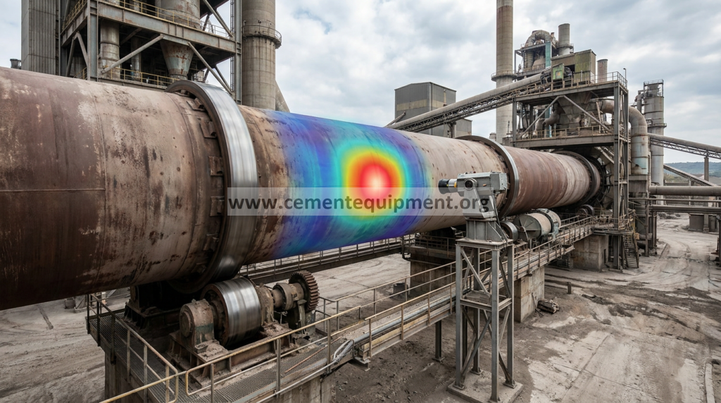
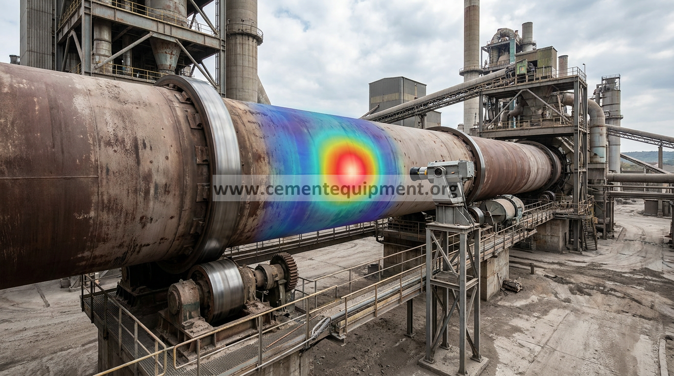
An infrared line scanner measures emitted thermal radiation from the external steel shell as the kiln rotates. Software combines successive scans with kiln position to build a two-dimensional thermal map: kiln length on one axis, circumference or rotation on the other, and shell surface temperature represented by colour.
The scanner does not directly measure refractory thickness. It measures shell surface temperature, which is influenced by refractory condition, coating, process heat load, shell emissivity, ambient conditions, obstructions, cooling air, and scanner geometry. For that reason, the most useful diagnostic signal is often not a single temperature value but a repeatable change in pattern.
Why refractory defects appear as thermal anomalies
The refractory lining is the thermal barrier between the hot process and the steel shell. When refractory becomes thinner, cracks, spalls, or separates locally, thermal resistance decreases and more heat reaches the shell. Loss of protective clinker coating can produce a similar rise because the refractory hot face is exposed to a higher heat flux.
A hot area therefore answers the question “where is heat transfer to the shell increasing?” It does not, by itself, prove the exact failure mode. The maintenance diagnosis must combine the thermal pattern with process history, refractory installation records, coating behaviour, kiln mechanical condition, and the location of the anomaly. For adjacent failure-mode analysis, see Burning Zone Refractory Failure: Analysis.
Five thermal patterns worth distinguishing
1. Localized hot spot
A compact hot area that persists at the same axial location and repeats through rotations deserves immediate investigation. Possible causes include localized brick loss, spalling, open joints, coating loss, or a damaged refractory patch. Persistence matters: a one-scan anomaly may be optical or environmental; a repeatable trend is stronger evidence of a real condition.
2. Broad zone temperature rise
A wider band that warms gradually across part of the kiln can indicate a process or coating change rather than a single missing brick. Review flame shape, burning-zone position, feed and fuel stability, coating history, and refractory campaign age before assigning a mechanical cause.
3. Migrating hot pattern
If the thermal anomaly changes position or expands over time, the trend can be more informative than its instantaneous peak. Migration may accompany changing coating conditions, a moving process zone, or progressive refractory deterioration. Trend snapshots should therefore be retained rather than overwritten.
4. Cold patch or cold band
Cold anomalies also matter. They can reflect heavy coating or material build-up, external cooling, shadows or obstructions, or a measurement artefact. A cold area should not automatically be treated as “healthy refractory.” Compare it with process conditions and the physical scanner line of sight.
5. Circumferentially repeating anomaly
A feature that appears at a consistent angular position each revolution can help separate a shell/refractory condition from a stationary environmental influence. Synchronization with kiln rotation is therefore valuable when the scanner system supports it.
How to diagnose a developing hot spot
- Confirm the measurement. Check whether the anomaly repeats over several rotations and whether the scanner view is unobstructed.
- Check scanner health. Review lens cleanliness, purge air, alignment, calibration status, communications, and kiln-position synchronization.
- Locate the anomaly precisely. Record axial position, circumferential position, refractory zone, nearby tyres or supports, and the installed refractory type.
- Compare with baseline. Use the normal thermal profile for the same kiln zone and similar operating state. Rate of change and persistence are usually more useful than an isolated colour.
- Correlate with process changes. Review feed, fuel, kiln speed, flame condition, coating behaviour, draft, and recent stops or startups.
- Review refractory history. Check lining age, brick or castable specification, previous repairs, known weak zones, and installation records. Where installation quality is part of the investigation, review Refractory Installation Techniques in Cement Industry.
- Classify the response under the plant procedure. The plant’s approved alarm matrix should define monitoring, escalation, process intervention, inspection, and shutdown decisions.
Do not use one universal shell-temperature limit
Published articles and vendor pages often quote specific “watch,” “alarm,” or “critical” temperatures. Those values can be useful examples, but they should not be copied blindly into a cement plant procedure. Safe limits depend on shell steel, kiln geometry, refractory thickness and chemistry, coating, scanner accuracy, location, duration of exposure, and OEM guidance.
A stronger control philosophy uses three layers: an absolute plant-approved limit; deviation from the normal zone baseline; and rate-of-rise or persistence logic. This prevents a seemingly moderate but rapidly worsening anomaly from being ignored while also reducing nuisance alarms caused by normal zone-to-zone differences.
Common false indications
| Observed condition | Possible explanation | Check |
|---|---|---|
| Sudden narrow hot line | Reflection, obstruction edge, or scanner artefact | Repeatability, lens, alignment, viewing geometry |
| Large cold area | External cooling or heavy coating | Cooling fans, process history, physical inspection |
| Temperature shift after maintenance | Changed emissivity or surface condition | Shell surface, scanner settings, baseline reset |
| Apparent moving anomaly | Position synchronization problem | Kiln encoder/trigger and software mapping |
| General zone warming | Process heat-load or coating change | Burning-zone and process trends |
Scanner maintenance matters as much as interpretation
A dirty optical window, failed air purge, poor alignment, unstable mounting, or lost rotational reference can turn a good scanner into a misleading instrument. Include the scanner in the preventive-maintenance program. At minimum, inspect optical cleanliness, purge-air condition, mounting, field of view, communications, position reference, alarm functionality, and data retention. Follow the scanner manufacturer’s calibration and verification requirements.
Build a useful refractory trend record
For each meaningful anomaly, retain the thermal map, time, kiln operating state, axial/circumferential location, refractory zone and material, operator action, follow-up scan, and final inspection finding. When a shutdown eventually exposes the lining, compare the physical refractory condition with the earlier thermal signature. This feedback turns the scanner from an alarm device into a plant-specific diagnostic tool.
Hot spot response: what the scanner can and cannot decide
The scanner can identify and trend abnormal shell heating. It cannot independently decide whether continued operation is safe. That decision belongs to the plant’s authorized operating and maintenance team using approved procedures and OEM/refractory guidance. Do not improvise cooling, burner changes, kiln-speed changes, water application, or continued operation solely from a generic internet threshold.
If a hot spot is confirmed, preserve the evidence, escalate according to the site’s alarm matrix, increase monitoring as required by procedure, and correlate the event with refractory and process history. If the plant procedure calls for a controlled stop or inspection, the thermal trend should support—not override—that decision.
Practical checklist for each shift
- Confirm the scanner is online and the kiln position reference is valid.
- Review the complete thermal map, not only the maximum-temperature alarm.
- Compare new anomalies with the previous stable baseline.
- Check whether the anomaly persists over multiple rotations.
- Record its exact kiln location and refractory zone.
- Correlate it with process and coating changes.
- Escalate according to the approved plant alarm matrix.
- Keep before-and-after thermal images for refractory campaign review.
Key takeaway
Kiln shell scanner troubleshooting is fundamentally a pattern-recognition and trend-management discipline. The best diagnosis combines repeatable infrared data, process context, refractory history, scanner health, and a plant-specific response procedure. Avoid treating one temperature number as a universal verdict.
This subject is part of the broader Infinity for Cement Organization technical package and resource library. Explore the main technical library at https://www.cementequipment.org/.