Quick engineering answer
Rotary-airlock rotor clearance should be measured and mapped, not judged from noise or leakage alone. Use feeler gauges at multiple blades and angular positions, compare tip and end clearances with the installed valve’s OEM limits, and investigate asymmetric wear for bearing play, shaft runout, housing distortion or localized damage.
Why Rotor Clearance Matters in a Cement Rotary Airlock
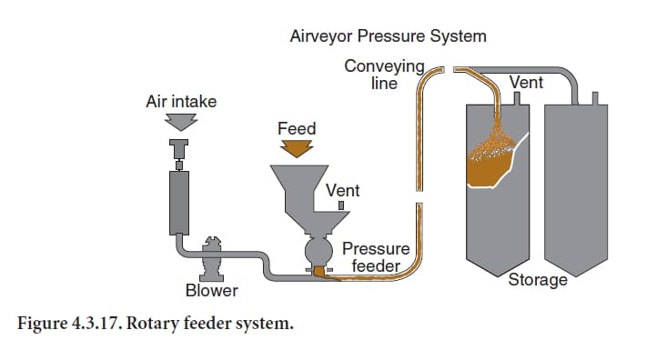
A rotary airlock must do two jobs at the same time: move dry bulk material through the rotor pockets and restrict unwanted air transfer between the inlet and outlet sides. As rotor tips, housing surfaces and end clearances wear, leakage increases. In pneumatic conveying this can reduce pocket filling, disturb material feed and increase the amount of air moving backward toward the hopper. Abrasive cement, raw meal, fly ash and mineral dust can accelerate wear, especially when foreign material or misalignment is present.
Rotor clearance should therefore be treated as a measurable maintenance condition, not as a vague judgment. Current rotary-valve maintenance guidance from ACS Valves specifically recommends checking rotor-to-housing tolerances with feeler gauges and explains that increased clearance leads to greater air leakage and reduced airlock performance. The exact acceptable clearance is application- and manufacturer-specific, so use the OEM value for the installed valve rather than copying a universal number.
Rotary Airlock Rotor Clearance Inspection Procedure
- Isolate the equipment. Stop feed, depressurize or vent the conveying line as required, isolate electrical power, and apply the plant’s lockout/tagout procedure before opening guards or accessing the rotor.
- Clean the measurement area. Remove compacted powder and buildup from the rotor tips, housing and endplate areas that will be measured. A layer of product can make a worn clearance appear smaller than it really is.
- Check free rotation. Rotate the shaft only by the approved maintenance method. Look for rubbing, binding, abnormal resistance, bearing roughness or contact between rotor and housing.
- Measure tip-to-housing clearance. Insert feeler gauges between a rotor tip and the housing at an accessible position. Repeat on several blades and at more than one angular position.
- Measure side/end clearance where applicable. Check rotor-to-endplate or rotor-to-sideplate clearance according to the valve design and OEM procedure.
- Record the pattern. Do not record only the largest gap. Write down each location so you can distinguish uniform wear from eccentricity, shaft movement or localized housing damage.
- Compare with OEM limits. Use the valve manual, certified drawing or manufacturer guidance for the installed rotor type, temperature and service.
- Inspect related components. Check bearings, shaft seals, endplates, drive coupling, gearbox, chain/belt drive and housing condition before deciding the rotor alone is responsible.
How to Read the Clearance Pattern
| Measured pattern | Likely interpretation | Next check |
|---|---|---|
| Similar increase on most rotor tips | General abrasive wear | Rotor-tip condition, housing wear and leakage trend |
| Large gap on one side, tight on the opposite side | Possible shaft/bearing alignment or housing geometry issue | Bearing play, shaft runout, endplate alignment |
| One blade differs from the others | Localized rotor damage or bent/worn tip | Blade condition and foreign-body history |
| Scoring or contact marks with small nominal clearance | Intermittent contact, thermal growth, distortion or bearing movement | Operating temperature, runout, bearings and housing distortion |
Repair, Adjust or Replace?
The measured gap alone does not decide the repair. Some rotary valves use fixed rotor tips, while others allow adjustable or replaceable tips. Housing or endplate wear may also make a new rotor ineffective if the mating surfaces are damaged. If the valve is part of a combustible-dust isolation strategy, any safety-related clearance requirement must be checked against the applicable OEM certification, plant risk assessment and current code basis before returning the valve to service.
- Adjust only when the installed rotor design is intended to be adjusted and the OEM procedure allows it.
- Replace rotor/tips when wear exceeds the manufacturer’s limit but the housing and shaft geometry remain serviceable.
- Repair housing/endplates when scoring, erosion or distortion is driving the clearance.
- Investigate bearings/alignment when the clearance is strongly asymmetric or changes with shaft position.
- Review upstream protection if repeated foreign-body damage is found; magnets, screens or tramp-material controls may be inadequate.
Rotary Valve Shutdown Inspection Checklist
- Rotor-tip clearance measured and recorded at multiple blades/positions.
- Rotor end/side clearance checked where applicable.
- Rotor tips checked for rounding, chips, scoring and embedded foreign material.
- Housing and endplates checked for grooves, erosion and buildup.
- Shaft runout or obvious eccentricity checked if wear is uneven.
- Bearings checked for play, temperature history and lubricant condition.
- Seals checked for dust leakage or product ingress.
- Gearbox, coupling, chain/belt and guards checked.
- Rotation direction confirmed before restart.
- Baseline leakage, feed stability and abnormal noise checked after restart.