Full Technical Guide
A pulse-jet bag filter can have healthy filter bags and still clean poorly when a diaphragm valve, solenoid pilot, tubing, timer output, or compressed-air path is not working correctly. The fastest way to diagnose the problem is to troubleshoot the cleaning chain in sequence—from the timer signal to the solenoid, pilot line, diaphragm valve, header, blow tube, and finally the filter row—rather than replacing parts at random.
What the diaphragm valve does in a pulse-jet bag filter
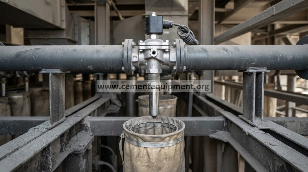
In a reverse-pulse dust collector, compressed air is stored in a header and released in a short burst through a pulse valve. The valve is normally closed. When the pilot solenoid is energized, the pressure balance across the diaphragm changes, allowing the main valve to open rapidly. The resulting air pulse travels through the blow tube and into the filter row, creating the cleaning action that removes the dust cake from the outside of the filter bags or cartridges.
Because the pulse event depends on several components acting in sequence, a weak cleaning pulse does not automatically mean that the diaphragm itself has failed. The fault can be electrical, pneumatic, mechanical, or contamination-related.
Common symptoms and what they usually indicate
| Observed symptom | Likely areas to inspect first |
|---|---|
| Valve does not pulse at all | Timer/controller output, electrical supply, solenoid coil, solenoid plunger, blocked pilot line, blocked exhaust path, diaphragm damage |
| Valve stays open or continuously leaks air | Solenoid not venting correctly, continuous electrical signal, contaminated valve seat, blocked bleed passage, damaged diaphragm or spring, insufficient pressure equalization |
| Pulse is weak | Low header pressure, restriction in the air supply, leakage, partially blocked pilot path, slow valve opening, contamination, poor blow-tube alignment |
| Only one row cleans poorly | Local solenoid, pilot tubing, diaphragm valve, blow tube, nozzle alignment, or row-specific mechanical obstruction |
| Several rows clean poorly | Compressed-air supply, header pressure recovery, controller settings, moisture/oil contamination, common electrical supply, or system-wide leakage |
| Differential pressure remains high although pulsing can be heard | Weak pulse energy, poor pulse distribution, filter blinding, excessive dust loading, airflow/can-velocity issue, or dust-discharge problem |
Use a system-level troubleshooting sequence
Manufacturer troubleshooting guidance for pulse-jet collectors consistently recommends checking the entire cleaning system rather than isolating the diaphragm valve too early. A practical sequence is:
- Confirm the cleaning demand or timer sequence. Verify that the controller is calling for cleaning and that the relevant output step is active.
- Confirm the solenoid is being energized. Check the electrical signal using the plant’s approved electrical test procedure.
- Confirm the solenoid pilot is switching. A powered coil does not guarantee that the plunger is moving freely.
- Inspect pilot tubing and fittings. Look for loose fittings, leaks, kinks, blockage, dust contamination, oil, or moisture.
- Confirm the diaphragm valve opens and closes sharply. A healthy pulse valve should not remain partially open or leak continuously after the pulse.
- Check header pressure and recovery. The header must recover adequately between pulses.
- Check the blow tube and the affected filter row. Misalignment, obstruction, or damaged hardware can make a healthy valve appear weak.
Safety before opening a pulse valve
Do not remove a diaphragm cover while the compressed-air header is pressurized. Isolate the collector according to the site’s lockout/tagout procedure, isolate electrical energy to the cleaning circuit as required, close the compressed-air supply, bleed stored pressure, and verify that the system is at a safe state before disassembly. Follow the valve and dust-collector manufacturer’s service instructions for the installed model.
Problem 1: the pulse valve will not open
If the valve never opens, start upstream. Check whether the timer or PLC is sending a pulse command. Then check the solenoid coil and pilot mechanism. Dirt, oil, moisture, or corrosion can prevent the solenoid plunger from moving even when the electrical signal is present.
If the solenoid works, inspect the pilot tubing between the solenoid and diaphragm valve. A blocked tube prevents the pressure change needed to lift the diaphragm. A leaking tube can also reduce the pilot signal enough to make the valve slow or unreliable.
When the pilot path is clear, inspect the pulse valve itself. Look for a torn or hardened diaphragm, blocked ports, damaged seating surfaces, contamination, or mechanical damage. Replace damaged elastomer components with the correct kit for the installed valve model rather than mixing incompatible parts.
Problem 2: the valve will not close or continuously leaks air
A pulse valve that stays open wastes compressed air, reduces header pressure for the other rows, and can make the whole cleaning system appear weak. The root cause may be inside the valve, but it may also be the solenoid or pilot circuit.
Check whether the solenoid remains energized after the commanded pulse. If the electrical signal is correct, inspect the solenoid for internal leakage and verify that the pilot line is not leaking. Then inspect the valve’s bleed passages and diaphragm seating surfaces. Blocked bleed passages can prevent pressure from equalizing across the diaphragm, so the valve may fail to reseat correctly. Dirt on the main seat, a damaged diaphragm, or a broken spring can create the same symptom.
If many valves leak after startup, examine the common air-supply and pressurization condition before assuming that all diaphragms failed simultaneously. A system-wide symptom usually points to a common cause.
Problem 3: the pulse sounds weak or inconsistent
A weak audible pulse can result from insufficient header pressure, slow valve opening, leakage, contamination, or restriction. Compare the affected row with a known healthy row rather than relying only on sound. Check the header pressure trend during a cleaning cycle and confirm that pressure recovers between pulses.
Also inspect the compressed-air quality. Water, oil, rust particles, and pipe scale can migrate into small pilot passages and the valve body. Cement plants are especially sensitive to this because dust and ambient moisture can combine with contamination to create deposits around small pneumatic passages.
After confirming the valve, inspect the blow tube and nozzles. A misaligned blow tube can waste much of the pulse energy even though the valve itself is operating correctly.
Problem 4: high bag-filter differential pressure remains after valve repair
Restoring the pulse valve does not guarantee that filter differential pressure will immediately return to normal. The filters may already be heavily loaded or blinded, or the collector may have another process-side problem. Review the trend instead of judging only a single reading.
Useful follow-up checks include filter condition, dust loading, hopper evacuation, air leakage, airflow distribution, pressure-sensing lines, and whether the cleaning controller is actually sequencing all rows. For a broader differential-pressure diagnostic procedure, see How to Diagnose High Differential Pressure Across a Cement Bag Filter.
How to distinguish solenoid faults from diaphragm faults
| Check | If abnormal | Likely direction |
|---|---|---|
| No electrical output to solenoid | Output missing when cleaning step is active | Controller, wiring, interlock, or power issue |
| Electrical output present but no pilot action | Coil energized, no mechanical response | Solenoid coil/plunger or contamination |
| Pilot action present but main valve does not open | Pilot vents but no main pulse | Pilot path, diaphragm, bleed passage, valve body |
| Main valve opens but does not close | Continuous air loss after pulse | Bleed passage, seat contamination, diaphragm/spring, solenoid leakage |
| Main valve cycles normally but cleaning is weak | Pulse present but filter row remains dirty | Header pressure, air supply, blow tube/nozzles, filter condition or process loading |
When cleaning is enough—and when to replace parts
Cleaning may be appropriate when the problem is clearly caused by loose contamination in the solenoid plunger area, pilot tubing, bleed passage, or valve seat and the components remain undamaged. Replace the diaphragm or valve kit when there is tearing, cracking, permanent deformation, loss of elasticity, damaged sealing surfaces, damaged springs, or recurring leakage after proper cleaning and reassembly.
Recurring failures deserve a root-cause review. Replacing the same diaphragm repeatedly without correcting wet compressed air, oil carryover, rust, pipe debris, poor filtration, or incorrect pilot plumbing simply resets the failure clock.
Preventive maintenance for pulse valves in cement service
- Keep compressed air clean and dry according to the collector and valve manufacturer’s requirements.
- Drain water from headers and air-treatment components as required by the plant’s maintenance standard.
- Inspect for continuous leaks; a small leak can lower available pressure for the rest of the cleaning system.
- Check pilot tubing and fittings for damage, looseness, contamination, and heat exposure.
- Observe pulse consistency across all rows during routine inspections.
- Trend header pressure and bag-filter differential pressure rather than relying on occasional spot readings.
- Use the correct OEM or compatible service kit for the exact valve model.
- After maintenance, verify the full cleaning sequence rather than testing only the repaired valve.
Practical field checklist
- Confirm the correct filter row and valve number.
- Verify cleaning demand/timer sequence.
- Verify electrical output to the solenoid.
- Check solenoid pilot action.
- Inspect pilot tubing and fittings.
- Check for continuous air leakage.
- Verify header pressure and recovery.
- Isolate and depressurize safely.
- Inspect diaphragm, spring, ports, bleed passages, seat, and body.
- Reassemble with correct parts and orientation.
- Restore air and power using the approved startup procedure.
- Verify a sharp pulse and complete reseating.
- Confirm the affected filter row is actually cleaning.
- Trend differential pressure after the repair.
Related Infinity for Cement Organization resources
For wider bag-filter maintenance and failure analysis, also see Bag Filter Maintenance for Cement Plant, Bag Filter Diagram: Parts, Working Principle and Design, and the broader Infinity for Cement Organization technical resource library. The subject is part of the wider maintenance, troubleshooting, process, and equipment material included across the organization’s technical package resources.
Conclusion
When a pulse-jet bag filter cleans poorly, diagnose the cleaning chain in order: controller, solenoid, pilot line, diaphragm valve, header pressure, blow tube, and filter row. This prevents unnecessary parts replacement and makes it easier to separate an electrical or pneumatic control fault from a genuine diaphragm failure. The most important maintenance lesson is that repeat valve problems usually require a system-level cause to be corrected, not only another replacement diaphragm.