Bag Filter Diagram: Flow Path and Main Sections
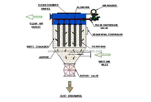
A bag filter (baghouse) removes dust by passing dust-laden gas through fabric filter bags while collected solids remain on the dirty side and fall to the hopper during cleaning. Read the diagrams on this page from inlet → dirty-gas chamber → filter bags/cages → clean-air plenum → outlet, with dust discharged through the hopper. For pulse-jet units, compressed-air pulses flex the bags and release the collected dust cake while the collector remains in service.

Bag Filter Schematic Diagram and Components
The schematic drawings below show the filtration and cleaning arrangement. Use them as an operating reference, not as a fabrication drawing: actual inlet geometry, compartment layout, bag length, cleaning hardware and hopper arrangement depend on the duty and OEM design.

Working from a plant drawing or troubleshooting a real collector? Use the diagram first, then calculate the filtration duty with the free Bag Filter Calculator. For the full technical-file library, see the $249.99 Complete Cement Industry Technical Package.
Main Components to Identify on a Bag Filter Diagram
| Component | Function | What to inspect |
|---|---|---|
| Dirty-gas inlet / distribution zone | Brings the dust-laden gas into the collector and distributes it across the filtering area. | Erosion, maldistribution, buildup and evidence of local high velocity. |
| Filter bags and cages | Provide the active filtration surface and mechanical support. | Tears, abrasion, collapsed cages, poor seating and dust tracking. |
| Tube sheet | Separates dirty and clean sides and seals each bag opening. | Leak paths, damaged holes, corrosion and poor bag-to-tube-sheet sealing. |
| Clean-air plenum / outlet | Collects filtered gas before the fan or stack. | Visible dust, leaking rows and abnormal chamber-to-chamber readings. |
| Pulse header, valves and blow pipes | Deliver the short cleaning pulse to rows of bags. | Air pressure, valve response, nozzle alignment, leaks and uneven cleaning. |
| Hopper and discharge device | Receives dislodged dust and removes it continuously. | High level, bridging, rotary-valve problems and air ingress. |
Pulse-Jet Bag Filter Working Principle
- Air along with dust particles under suction or pressure enters the lower portion i.e. hopper of the bag filter.
- The air travels through the filter bag, which retains the dust particles on surface of the bag, and the clean air passes out through bags and plenum to the outlet of Bag filter.
- Dust is collected on the outside the bag filter
- Accumulation of dust on bags causes an increase in the differential pressure across the filter bags. Compressed air is pulsed by a timer actuated series of normally closed pulse valves at preset intervals causing the valves to open.
- A momentary rush of high- pressure air (4-5 bar) flows from the compressed air header to the blow tube and is expelled from the blow tube through nozzles at a high velocity (primary air flow). Air from each nozzle induces a secondary airflow. The combined effect of the primary and induced secondary air causes an instantaneous pressure rise on the clean side of the filter bags, causing a reverse flow air through the filter bags, thus dislodging the dust particles held on the outer surface of the bags.
- By this mechanism, the dust collected is released from the bags and falls into the hopper & the differential pressure is controlled across the Filter Bags.
- From this hopper it is discharged through suitable device i.e. Rotary valve.
- Since only fraction of the total filter area of the bag filter is cleaned at any giventime, continuous flow through the bag filter at rated capacities is assured.
Bag Filter Design Checks
Air-to-cloth ratio (filtration velocity) = actual volumetric gas flow ÷ active filter-cloth area. It is a primary baghouse sizing check; the acceptable value depends on dust loading and properties, gas conditions, fabric, cleaning method and the OEM design. Do not copy a single universal ratio from another plant without checking those conditions.
| Design / operating variable | Why it matters | Useful check |
|---|---|---|
| Actual gas flow | Sets filtration velocity and duct loading. | Confirm the flow is on an actual operating basis, not confused with normalized flow. |
| Active cloth area | Controls air-to-cloth ratio. | Use net online area if a compartment can be isolated from service. |
| Differential pressure | Reflects resistance across the bags and dust cake. | Trend DP with flow and cleaning activity; investigate a sustained shift rather than a single reading. |
| Gas temperature / moisture | Controls fabric suitability and condensation risk. | Keep the gas safely within the selected media limits and away from condensation conditions. |
| Cleaning air | Determines whether dust cake is removed evenly. | Check header pressure, pulse valves, blow-pipe alignment and sequence. |
| Hopper evacuation | Prevents re-entrainment and buildup. | Verify level, rotary valve / screw operation and airlock condition. |
For sizing work, use the free Bag Filter Calculator. For media selection, continue to the filter-media selection guide.
Worked Air-to-Cloth Ratio Check
If the actual gas flow is 60,000 m³/h and the active cloth area is 10,000 m², the filtration velocity is 6 m/h, or 0.10 m/min. That calculation alone does not prove the design is acceptable: compare it with the OEM basis for the dust loading, particle properties, fabric, cleaning method, temperature and moisture conditions.
Five-Step Diagram Walkdown
- Identify the dirty-gas inlet and the clean-gas outlet.
- Trace the gas path through the bag field and clean-air plenum.
- Locate the differential-pressure measurement points across the filtering section.
- Trace compressed air from the header through pulse valves and blow pipes to the bag rows.
- Trace collected dust from the bag surface to the hopper and through the discharge airlock.
Bag Filter Troubleshooting from the Diagram
| Symptom | Trace on the diagram | First checks |
|---|---|---|
| High differential pressure | Inlet → bags → clean plenum | Gas flow, dust loading, sticky/condensing dust, cleaning sequence, pulse pressure and hopper discharge. |
| Dust at clean-gas outlet | Bags / tube sheet → clean plenum | Broken bag, poor bag seal, damaged tube sheet or leakage around a row/compartment. |
| Uneven bag life | Inlet distribution + bag field | Local abrasion, gas maldistribution, temperature excursions and misaligned cleaning jets. |
| Dust buildup in hopper | Hopper → discharge airlock | Bridging, high level, rotary-valve/screw failure, air ingress and insufficient evacuation. |
| Excess compressed-air use | Header → pulse valves → blow pipes | Leaks, over-cleaning, failed diaphragm valves and an unnecessarily aggressive cleaning cycle. |
Continue with the bag-filter maintenance guide, the differential-pressure trends guide, or the broader bag filters in cement plants reference.
Need the full bag-filter drawings, manuals, courses and calculation sheets? See the $249.99 Complete Cement Industry Technical Package.

1. whats rating of micron
2. No of pocket in bag filter