Vertical Roller Mill: Parts, Diagram & Working Principle
A vertical roller mill (VRM) grinds and dries material on a rotating table using hydraulically loaded rollers while hot gas carries the fine product to a dynamic separator. The main assemblies are the grinding table, rollers, rocker arms, hydraulic loading system, separator, nozzle ring, mill housing, gearbox, main motor, reject system and lubrication equipment.
Use this page as the component map. For failure diagnosis and operating problems, continue to the VRM technical guide, the dam-ring guide, or the VRM vs ball-mill comparison.
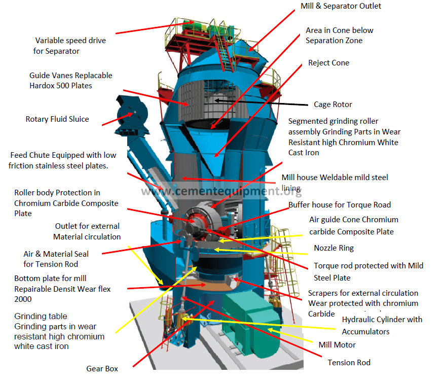
How a vertical roller mill works
Feed enters near the centre of the rotating grinding table. Centrifugal force moves the material outward into the grinding track, where the rollers apply pressure and shear. Hot process gas enters through the nozzle ring around the table, dries the material and lifts fine particles toward the separator. The separator rejects coarse particles back to the grinding zone while finished product leaves with the gas stream. Material too coarse or too heavy to be lifted can fall through the nozzle ring into the reject system and be returned to the mill circuit.
VRM performance therefore depends on several systems working together: stable feed, adequate grinding pressure, correct table speed, controlled gas flow, sufficient drying capacity, separator speed, appropriate dam-ring height and a healthy hydraulic/lubrication system.
Vertical roller mill parts and their functions
| VRM component | Primary function | Typical condition to watch |
|---|---|---|
| Grinding table | Supports the material bed and transmits drive torque into the grinding process. | Wear profile, cracks, uneven bed formation. |
| Grinding rollers | Apply compressive and shear forces to the material bed. | Segment wear, vibration, bearing temperature, uneven loading. |
| Rocker arms / roller suspension | Transfer hydraulic force to the rollers and allow controlled movement. | Pins, bushings, cracks, alignment and free movement. |
| Hydraulic loading system | Controls grinding pressure and provides a compliant response to bed variation. | Accumulator pressure, oil leakage, cylinder condition, unstable pressure. |
| Dynamic separator | Controls product fineness by separating fine product from coarse returns. | Rotor wear, speed, blade condition, material build-up. |
| Nozzle ring | Accelerates gas around the table edge to lift and transport particles. | Wear, blockage, gas velocity imbalance, excessive rejects. |
| Dam ring | Helps retain an adequate material bed on the table. | Excessive or insufficient bed depth, vibration and circulating load. |
| Main gearbox | Reduces motor speed and transmits high torque to the grinding table. | Oil cleanliness, bearing condition, gear vibration, temperature. |
| Main motor | Provides the mechanical power required by the grinding table. | Current, winding/bearing temperature, vibration and load trend. |
| Reject system | Collects coarse material passing through the nozzle ring and returns or discharges it. | High reject rate, metal contamination, blockages. |
Grinding table and material bed
The grinding table is not only a rotating wear surface; it is the foundation of VRM stability. A uniform material bed cushions the roller-to-table contact and allows grinding pressure to be converted into useful comminution. If the bed becomes too thin, vibration can rise sharply. If the bed becomes too thick, grinding efficiency and gas transport can deteriorate. Feed size distribution, moisture, table speed, grinding pressure and dam-ring height all influence bed behaviour.
Grinding rollers and hydraulic pressure
Rollers must follow changes in bed thickness while maintaining sufficient force for grinding. The hydraulic system supplies this force and accumulators provide elasticity to absorb short-term process disturbances. A VRM with unstable hydraulic pressure can show high vibration, poor product consistency or repeated lifting of rollers. Mechanical inspection should therefore consider hydraulic pressure together with roller wear, bearing condition, rocker-arm movement and table condition rather than treating each item independently.
Separator and product fineness
The dynamic separator is the classification stage of the VRM. Increasing separator speed generally makes the cut finer, while lower speed allows coarser product to leave the circuit. The final result also depends on gas flow, feed rate, internal circulation and the condition of separator blades. If fineness changes without an intentional separator-speed change, check for wear, deposits, false air and changes in circulating load.
Nozzle ring, gas flow and rejects
Hot gas performs two jobs: drying and pneumatic transport. The nozzle ring establishes the gas velocity around the table edge. If gas velocity is too low for the current feed and particle-size distribution, rejects can increase and internal material circulation can become unstable. If gas flow is excessive, pressure loss and fan power rise and the mill can carry more coarse material upward than desired. Always evaluate rejects together with differential pressure, vibration, gas flow and product fineness.
Dam ring height
The dam ring influences material retention on the table and therefore bed thickness. There is no universal ideal height: the correct setting depends on mill design, feed characteristics, wear condition and operating target. A change in dam-ring height should be evaluated against vibration, mill differential pressure, rejects, specific power and product quality. See the dedicated VRM dam-ring optimization guide.
Common VRM symptoms and what to inspect first
| Symptom | First checks |
|---|---|
| High vibration | Material bed, feed stability, hydraulic pressure, table/roller wear, foreign material and gas flow. |
| High rejects | Nozzle-ring condition, gas velocity, feed size, grinding pressure and dam-ring setting. |
| Product too coarse | Separator speed/condition, grinding pressure, feed rate, internal circulation and roller/table wear. |
| High mill differential pressure | Internal circulation, gas flow, feed rate, separator rejects, material build-up and moisture. |
| High gearbox temperature | Oil level/quality, cooling system, filters, bearings, gear load and vibration trend. |
VRM inspection checklist
- Trend mill vibration, differential pressure, motor power and hydraulic pressure together.
- Inspect roller and table wear profiles, not only total wear thickness.
- Check accumulator pressure and hydraulic leakage.
- Inspect nozzle-ring wear and blockage and review reject quantity.
- Inspect separator blades, rotor condition and build-up.
- Trend gearbox oil temperature, contamination and vibration.
- Check lubrication lines, filters and bearing temperatures.
- Review dam-ring condition and material-bed stability after major wear changes.
Roller vrm patsh name
Vrm ke roller ke Pat’s name