Rotary Kiln Design Important Formulas
Inderjeet Singh Sidhu , Sr.GM Technical at Hyderabad
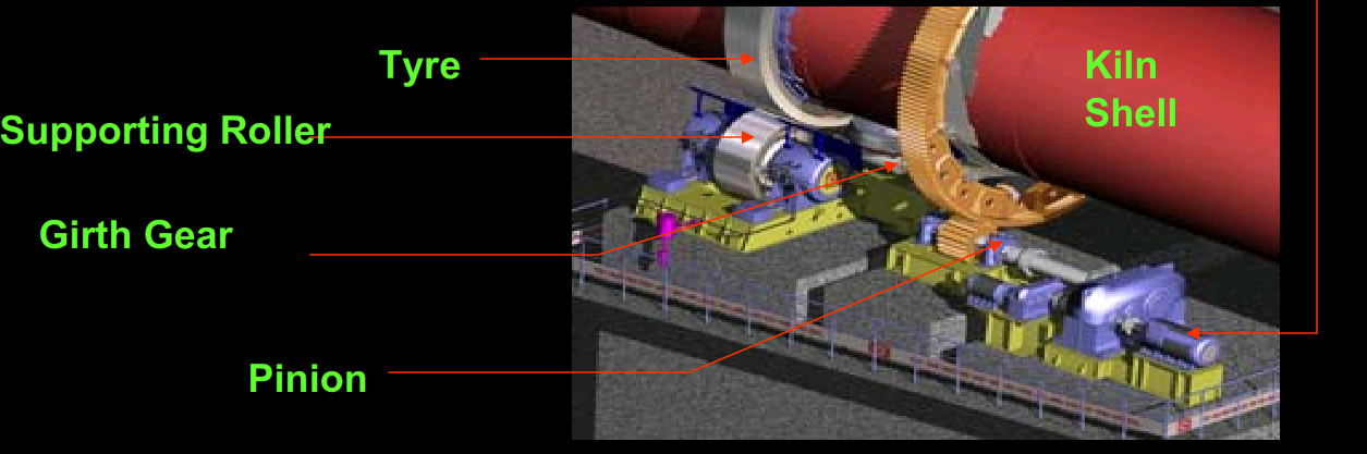
Kiln Tyre Material :
GS 24 Mn 5 (Normalized Cast Steel)
Kiln Tyre Dimension:
5620 OD x 4581 ID x 775 (width)
Supporting Rollers Assemblies Material :
CS 640 (Normalized Cast Steel)
Supporting Rollers Assemblies Dimensions :
5620 OD x 4581 ID x 775 (width)
Kiln Main Drive Motor , Gearbox , Pinion Formula
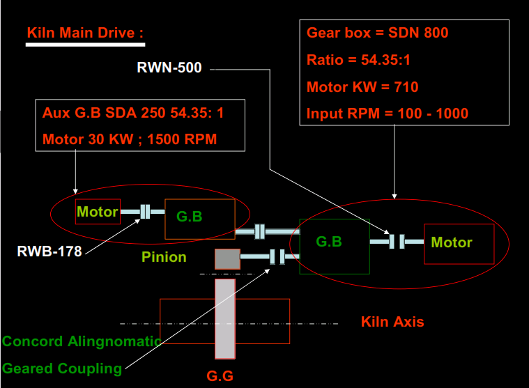
Rotary kiln main-drive calculations: power, speed and torque
The drive diagram above is an illustration, not an equipment datasheet. Use these basic mechanical relationships as a check on units and input data; final sizing requires the kiln OEM’s load cases, gear ratings, service factors and approved drawings.
- Torque from power and shaft speed:
T (N·m) = 9550 × P (kW) / n (rpm), where P is the mechanical power at the shaft whose torque is being calculated. The coefficient is rounded; it follows fromP = 2πnT/60with consistent SI units. - Gear reduction:
n_out = n_motor / i_totalwhere i_total is the overall speed-reduction ratio. Account for every gearbox and girth-gear stage. - Power after transmission losses:
P_out = η_total × P_in, using the applicable efficiency estimate or measured shaft power. Do not apply motor nameplate power as if it were actual running load. - Pitch-circle tangential force:
F_t (N) = 2 × T (N·m) / d (m)for a gear of pitch diameter d. This does not alone determine bearing reactions, tooth stresses or tooth life.
Illustrative arithmetic only: for 250 kW mechanical input, assumed overall efficiency 0.90 and a kiln output speed of 3 rpm, output power is 225 kW and output torque is approximately 716 kN·m. This is not a recommended drive rating or an operating setpoint.
Tyre and support-roller dimensions: verify the source
If a tyre’s stated outer diameter is 5620 mm and inner diameter is 4581 mm, the nominal radial ring thickness calculated from those figures is (5620 − 4581) / 2 = 519.5 mm. This simple geometry does not establish tyre clearance, shell ovality, support-roller geometry, hot alignment or permissible stress. The source text repeats the same dimensions for the support-roller assembly; treat that repetition as unverified, not as proof that the tyre and roller have identical dimensions. Obtain certified equipment drawings and material certificates before procurement or adjustment.
For more free context, read Kiln Roller Adjustment and Skew and the Rotary Kiln engineering guide. Any alignment, load or drive change must follow the plant’s mechanical engineering review and OEM procedures.
I want to be s’inscrive with your site
I want dépositaire my idies
Supporting Rollers Assemblies Dimensions :
5620 OD x 4581 ID x 775 (width)
Is wrong because you wrote same of Kiln Tyre Dimension
What is GS means