Contents
click here to download Holcim , fls smidth , Lafarge , Most importnant manuals , most important excel sheets
PREHEATER BLOCKAGES Problem Diagnosis and solution
By Pedro Montes de Oca and Jonathan Forinton
[email protected] [email protected]
types of cause
mechanical
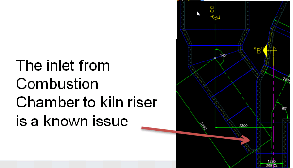
- design of ducts/cyclones
- equipment damage
chemical
- chlorine
- sulphur
MECHANICAL ASPECTS
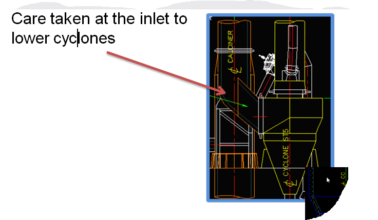
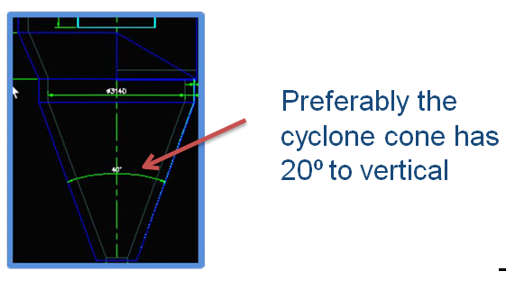
Dip tubes or refractory pieces can block cyclone cones. Standard test is to throw a light bottle down. No steel balls!
Chemical Causes
Chemistry of buildups
Buildups are caused by melt formation followed by solidification that acts as binder for dust particles to agglomerate
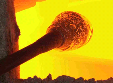
agglomeration due to the presence of molten alkali chlorides
Consequence: preheater blockages
Composition of Buildups:
Analysis leads to cause of formation
- formation is dependent on the presence of molten salts, especially alkali sulfates and chlorides.
- Samples show that the alkali, S and Cl concentration in the build-up material is significantly higher than in the kiln feed
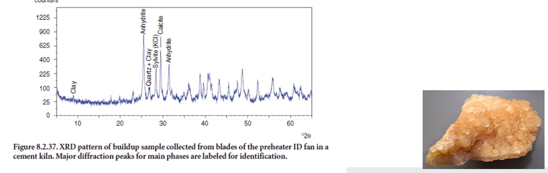
Deposits and link to operation
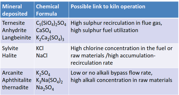
Affinity
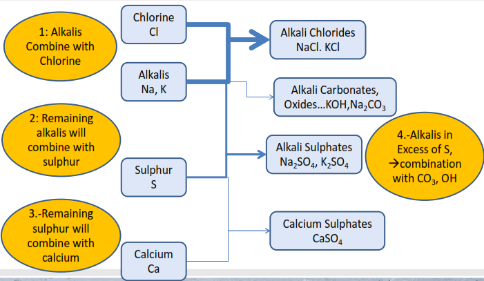
Alkalis will preferentially combine with any chloride present. Best A/S ratio is when there is just enough sulfur present to combine stochiometrically with the remaining alkalis.
excess of sulfur, > CaSO4 formation> sulphur in CaSO4 will volatilize completely.
excess of alkalis >alkali aluminate can form > stiffening problems in concrete and mortar.
Bypass > alkali in excess possible > low alkali cement + no stiffening problems >no sulphur excess problems.
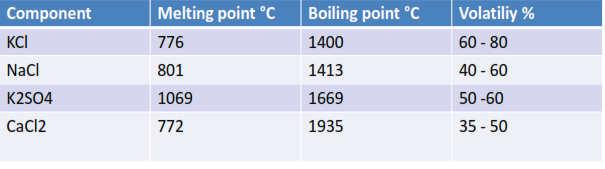
Chemical Causes Volatility
Melting and Boiling points
Trapped in kiln system due to physical properties
Recirculation of volatiles
Effects :
Transfer of Thermal profile of kiln
Kiln Conditions:
Factors that affect volatility
Gas velocity:
A higher gas velocity reduces the vapor pressure of volatiles in the atmosphere, increasing their volatility.
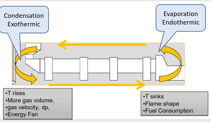
A higher sinter zone temperature as required for harder burning mix will increase volatility. Easier burning material less burning zone temperature less volatility.
Residence time at high temperature: longer time at high temp. increases volatilities and the amount of volatiles main burner flame shape
A higher CO2 concentration in the kiln will increase volatility of sodium and potassium.
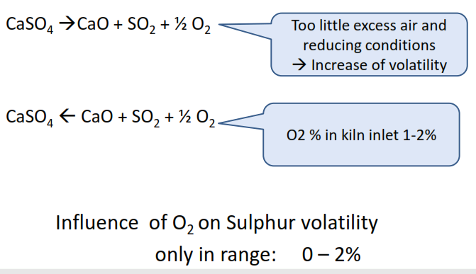
Reducing conditions will increase the volatility of sulfur, while higher oxygen levels will decrease it (up till 2%)
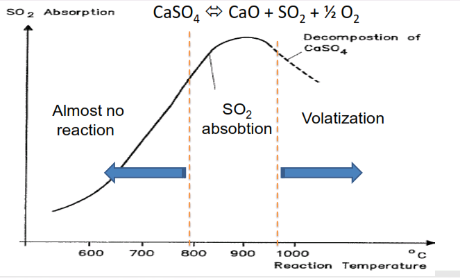
Sulphate – SO2 equilibrium reaction Temperature
Sulphate – SO2 equilibrium reaction Oxygen
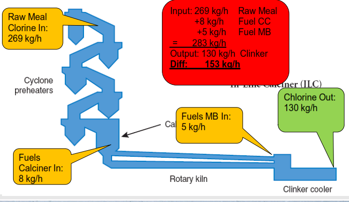
Typical Cl – Mass Balance
Operational issues
BLOCKAGES AND PERFORMANCE
Build-ups
increasing build-ups cause reduced gas flows at the same ID fan pressure
Fluctuating gas flows
due to fluctuating O2 and heat levels, CO-increases and excess O2 requires ID fan increase
• Fluctuating fuel
fluctuating temps cause fuel increase, thereby increasing S or Cl inputs
• Cold Air Ingress
Increasing the ID fan to keep up, kiln inlet under-pressure increase draws in more false air
• Circulating Phenomena
Destablized operation, CO increase and false air cause volatization to spiral out of control
• Blockages
increasing volatization causes more build-ups. Return to the start…
INVESTIGATION STEPS
- General description of situation (position of build-ups, reproducible conditions that seem to lead to the situation)
- Ongoing analysis of hot meal (LOI, SO3, Cl, Na2O, K2O, CaO)
- Pyro-section mass and heat balance
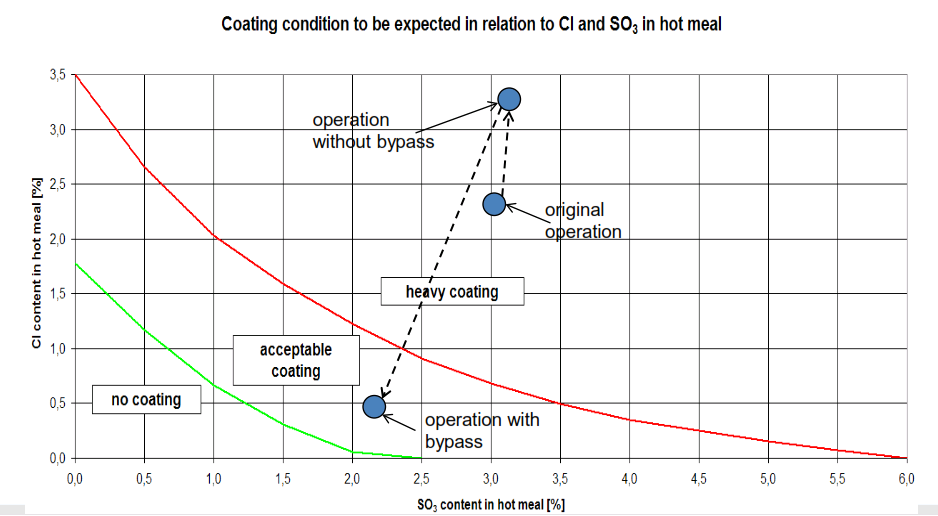
- Plot ongoing points on Cl-SO3 graph
- Sample the build-up material (XRF)
- Analyse Inputs-Outputs for responsible circulating element
RESULTS OF BUILD-UPS SEVERE!
- Blockages cause unplanned shut-downs and loss of earnings
- Constant start-up and stop decreases refractory life
- Build-up and dropping off causes mechanical wear of refractory
- Severe safety issues involved with cleaning big build-ups
- Clinker quality fluctuations + restarts = lots of rejected clinker
- Increased heat energy use due to:
- dusty clinker reduces radiation inside kiln
- more false air and operation at more excess air
- Increase shifts to cope with cleaning and higher maintenance
- Lower possibility to use alternative fuels because heat levels lower
- Clinker cooler instability means increased cement setting times
- Lower production level if preheater, kiln inlet, burner, or cooler is the bottleneck
- Lower production because away from optimum performance
- Increase wear on burner and refractories due to dust and velocities increase
OPTIMUM EQUIPMENT REDUCES OPERATIONAL DISTURBANCE
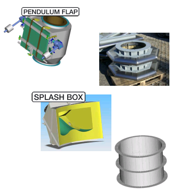
Pendulum flaps
Reliable operation.
Low maintenance.
Increased thermal efficiency.
Expansion joints
improper joints split and let in false air
Splash boxes
Optimized homogenous meal distribution.
Improved heat exchange.
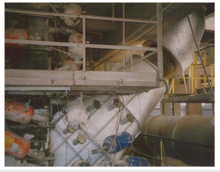
Dip tubes
Easy to install, long lifetime
MAIN BURNER AFFECTS VOLATILITY
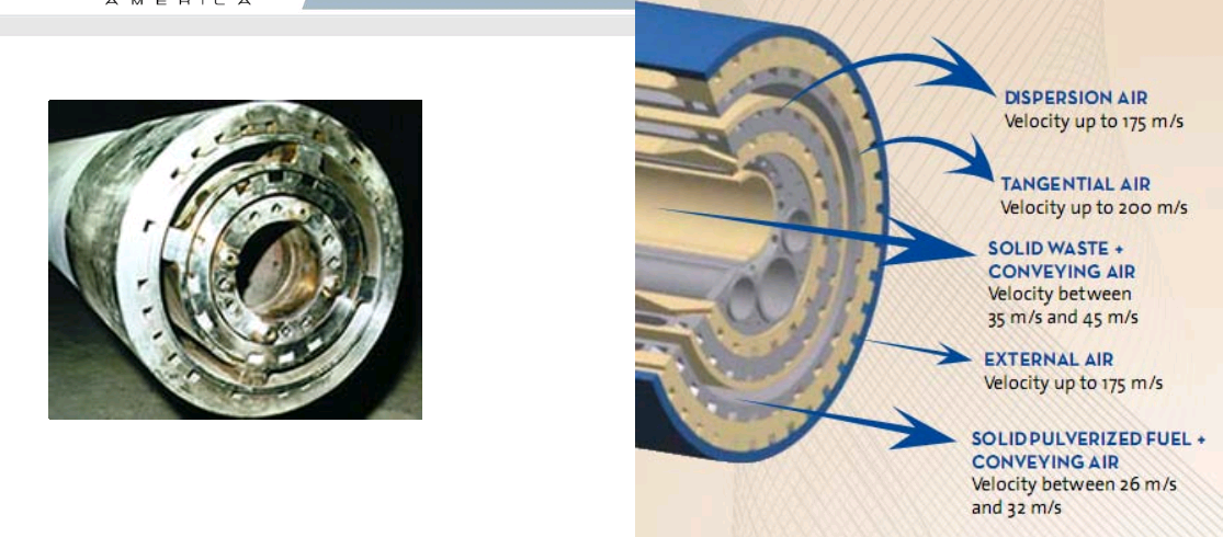
FLEXIFLAMP”‘ burners are the most advanced techno logy developed by Greco for rotary kilns firing pulverized f uel. Using three shaping airflows and a unique design- two of the airflows rotate to enfold the solid fuel injection flow- it allows,through simple procedures,to optimize complex fuel firing and great control over NOx emissions.
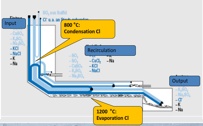
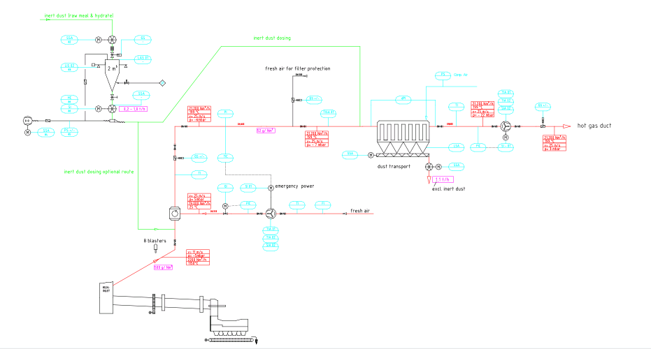
Chlorine Bypass
CL-SO3 balance on fuel change
BYPASS TAKE -OFF
Main Advantages:
- Big take off area
- Low take off velocity
- Particles < 10 µm
- No cyclones needed
- Gas can be used for raw meal drying to reduce thermal losses
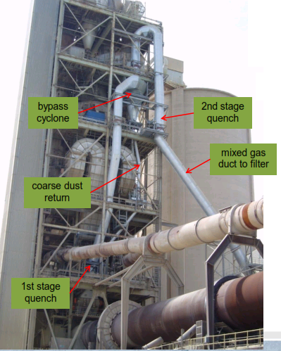
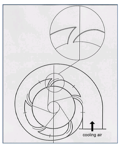
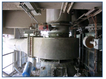
QUENCH CHAMBER
-Made completely of metal(no lining required).
-Cooling in one step to 200 °C.
-Minimum space requirement.
-Simple functionality.
STANDARD BY-PASS FLOWSHEET
Cl REDUCTION
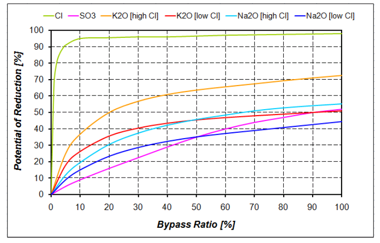
10 % bypass rate is sufficient for chloride bypass systems
TYPICAL RESULTS
-Kiln gas take off quantity 6’000 Nm³/h
-First stage cooling from 1100 ºC to 450 ºC
-50% coarse dust removed in cyclone, returned to kiln inlet or circulated in cyclone riser
-Second stage cooling from 450 ºC to approx 220 ºC
-Gas filtration system with max. dust quantity of 10 mg/Nm³ is positioned on top of bypass dust silo
-Cleaned bypass gas 59’000 Nm³/h design is ducted to main stack
-100% of dust is transported to special storage area; silo discharge capacity 30 t/h
EXAMPLE INSTALLATION
Advantages
Reliable operation.
Low maintenance
No big civil engineering
No refractory after takeoff
Cheap and simple to install
Reference
solicito informacion del producto.