Contents
CLINKER COOLING & COOLER SYSTEMS
CLINKER FORMATION AND CLINKER GRANULOMETRY
It is a well-known fact that the granularity of clinker products can vary considerably from one cement plant to another. Even kilns within the same plant are often found to produce quite different clinker, although fed with the same raw mix. Fig 1 shows some sieve test results obtained from a wide range of clinker samples. It appears that the dust content, for example grains finer than half a mm, can vary between 1 and 70%. Also the presence of even a small proportion of oversize clinker, say bigger than 40 mm, contributes very much to the overall appearance of a clinker product. Further, clinker made up of compactly fused and well shaped nodules appears to be completely different from clinker with a similar sieve curve, but consisting of coke like and sharp edged agglomerations of dust particles.
Such observations have naturally led to investigations of the factors affecting clinker formation.
In a wet-process kiln in which strong nodules come out from the chains, the clinker size is already to a great extent determined during the drying of slurry. In other kiln types it is obvious that the formation of nodule shaped clinker must take place in or just above the burning zone, since the raw mix somewhere further up in the kiln is in the form of meal.
In these kilns clinker formation is related to raw mix composition and to operating conditions. The clinker formation may start already in the calcining zone, where a certain agglomeration of the fine, solid particles may take place aided perhaps by the presence of low melting alkali salts. However, the final result depends on what happens in the burning zone.
Here the formation of liquid phase begins at a temperature slightly below 1300°C, and the quantity of liquid increases with the temperature up to a certain final value (Fig. 2).
The amount of liquid does not increase gradually with the temperature, but in steps on reaching certain temperatures. Only by applying extreme temperatures can this final amount of liquid be further increased which, however, usually has disastrous effects on coating and lining.
The quantity of liquid phase at normal burning temperature amounts to 20-25% of the clinker, depending on the content of alumina, iron, magnesia, and alkalis. If the quantity of liquid phase is too small, good clinker formation will not take place. Conditions may then be improved by changing the raw mix composition, which in practice is usually done by adding iron ore, thus reducing the silica ratio.
In some cases it will also be possible to improve the clinker formation by burning harder, even harder than required for bringing down free lime, the reason, of course, being an increase in liquid phase. But it is often seen that if the burning temperature is raised even further, the result will be dust clinker, probably due to a too low viscosity of the liquid. At several plants we have also found a rather sharp limit to the lime saturation factor, if good clinker grading is to be obtained; by exceeding this limit the clinker becomes dusty.
The clinker granulometry is important for the satisfactory operation of any cooler. There must not be too much dust. Less than 15% minus 0.5 mm is good.
Too much clinker plus 25 mm increases the clinker temperature after the cooler because of the too slow cooling of this fraction. Less than 10% plus 25 mm is good.
The clinker dust in the cooler tends to blow back into the kiln, thus establishing a dust circulation between kiln and cooler. The dust can disturb the radiation from the flame in the kiln, and often it spoils the clinker formation so that the dust circulation tends to accelerate.Dust circulation means that the amount of heat contained in the clinker entering the cooler increases, which will lower the efficiency of the cooler.
IMPORTANCE OF THE COOLER EFFICIENCY FOR THE HEAT CONSUMPTION.
A characteristic heat balance for a kiln with a 4-stage preheater and old type grate cooler can look like this: (Ref. temperature 18°C)
Heat in exit gas + dust 177
Surface loss kiln 56
Surface loss preheater 24
Cooler loss 142
Heat of reaction 417
_______________________________________
816 KCal\kg
– Heat in kiln feed, fuel, and
primary air 26
Heat consumption 790
_______________________________________
If we look at the possibilities of bringing down the heat consumption, then about 25 kcal/kg can be saved in the exit gas by adding a 5th cyclone stage to the preheater, but in some plants the full amount of heat in the exit gas is used for drying the coal and raw materials, so this heat is not wasted.
Using a type of insulating bricks in part of the kiln can bring down the surface loss from the kiln shell, but these bricks have generally a poor lifetime.
A better insulation in the preheater will partly result in a higher exit gas temperature instead of saved heat input to the system.
Regarding the cooler, it is so that if we could establish a perfect counter flow in the heat exchange between clinker and air, then nearly all the heat in the clinker could be transferred to the combustion air. Therefore, the largest potential for bringing down the heat consumption rests with the cooler.
3. COOLER TYPES
In the following the three types of coolers, considered by the industry for modern cement kilns, are discussed, i.e. planetary coolers, rotary coolers and grate coolers.
3.1 Planetary Coolers
The planetary cooler has served the cement industry for many years and was originally designed for wet process kilns with a high amount of secondary air available for the cooler.
In modern dry process kilns with a low heat consumption the amount of secondary air available for cooling, when this is done with secondary air only, is about 1 kg air per kg clinker or even less. This requires a very efficient heat transfer between air and clinker obtained by cascading the clinker through the airflow. It also requires that the internal parts in the hot end can stand high temperatures, which is obtained with wear resisting ceramic materials.
Compared to the old coolers only the principle of having a number of cooler tubes rotating with the kiln and connected directly to the kiln is maintained, so that sealing problems are avoided.
A breakthrough for the new planetary cooling principles came when a kiln support below the cooler was introduced.
This permits heavy cooler tubes with the necessary internal fittings to be supported without excessive stresses in the kiln shell and has opened the way for designing planetary coolers for kilns with a high capacity. The one shown (Fig. 3) is producing 4000 t/d clinker, and the cooler consists of 10 tubes, each 2.4 x 29 m. Only for kilns with less than about 1000 t/d capacity it is economical to leave out the support below.
Each cooler tube is attached to the kiln with a fixed and a movable support, welded to heavy kiln sections. (Fig. 4)
The inlet to the cooler has a special design, which prevents clinker from falling back into the kiln when a tube is in top position.
At the cooler outlet the fine clinker falls through a grizzly to the clinker transport, while coarse clinker and lumps are discharged at the side to a hammer mill clinker crusher.
The cooling is based upon cascading the clinker through the airflow.
This is not as simple as it seems, as fine clinker falling down from the lifters through the air is carried the wrong way by the air, and an excessive number of lifters has proved to lead to overfilling the coolers, back spilling into the kiln and high exit clinker temperatures.
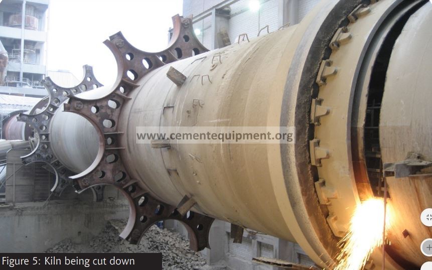
The shape and number of the lifters in the various temperature zones have to be carefully determined by means of a mathematical model, the input being an anticipated grading of the clinker. (Fig. 5)
In principle, coarse clinker requires more cascading and fine clinker less in the hot end of the cooler in order to avoid excessive circulation between cooler and kiln, which conveys more heat to the coolers.
The inlet part with a special shape is lined with castables. In recent years special, dense castables have been developed for such a purpose, fulfilling all requirements regarding abrasion resistance, shock resistance, chemical resistance against alkali attack etc., and the practical experience with these modern castables has been very good.
In the cylindrical part of the coolers there is first a section of corrugated brick lining, followed by cast heat resistant steel lifters of special design, either lined with steel plates, as shown, or for the hot part with a ceramic lining, either bricks or castables.
In the cold end of the coolers mild steel lifters with a high lifting capacity, increasing towards the outlet, are used, and no lining is used here.
The outlet of the kiln to the coolers was previously made with steel casings, which caused problems when exposed to high temperatures. The problems have been solved by using a ceramic outlet made of the high quality, dense castables now available.
The cooling effect depends, of course, on the size of the cooler. It can be expressed as the clinker production in relation to surface and volume for the cooler tubes by the following formula:
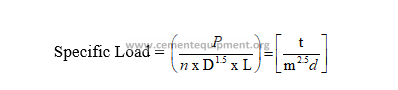
Where
P = clinker production in t/24 h
N = number of cooler tubes
L = length of cooler tubes in m
D = cooler tube diameter in m
A normal specific load would be 3.65 t/m2.5
The air velocity in the cooler tubes should not be too high to avoid excessive dust circulation. Therefore the expression:
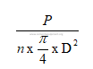
should not exceed 70 t/m2
The average temperature of the clinker from a planetary cooler of an economical dry process kiln will usually be 150°C above ambient temperature. It can vary with the clinker grading, and, of course, it increases by forced output. The temperature can be reduced, if required, by addition of water to the coolers near the outlet.
The equipment required is very simple: Just a gutter around the coolers, from which the water runs into the individual cooler tubes. The amount of water is controlled by the clinker temperature, and it has been established that 1 % water on clinker basis reduces the clinker temperature by about 15 – 20°C, which is close to the theoretical maximum. The effect on the heat consumption is therefore small, as long as the amount of water is kept below 3% of the clinker weight.
The heat losses from a planetary cooler consist of radiation loss and sensible heat in the clinker leaving the cooler. A normal cooler loss would be: (20°C ref. temp.).
| Radiation | 97 kcal/kg |
| Clinker (150°C) | 25 kcal/kg |
| Sum | 122 kcal/kg |
This compares very favorably with an old type grate cooler especially when also the lower power consumption is taken into consideration.
Depending on the cost relation between fuel and power, 1 kWh/t will often correspond to the cost of 7 kcal/kg clinker.
It would, of course, be possible to insulate the cooler much better, but that would lead to an excessive clinker temperature – a certain amount of heat has to be wasted through radiation. The length of the different types of lining has to be chosen so that the cooler shell temperature does not become excessive at any point.
Another favorable feature is the low power consumption, only about 1.0-1.5 kWh/t clinker added to the kiln drive and exhaust fan.
The Planetary cooler is unique in its simplicity, no excess air to handle, no motors or fans, no instruments. In operation, there is nothing to control, it is self-adjusting.
One disadvantage is that the clinker temperature is somewhat higher than for grate coolers, but normally that does not cause any problem. The higher noise level can also be a problem in some cases.
3.2 Rotary Cooler
It is a main drawback of the planetary cooler that it is not suited for precalciner kilns with external tertiary duct. This has given the separate rotary cooler a come-back.
The rotary cooler is also operated without excess air and permits to take out tertiary air for a precalciner through a specially designed kiln hood.
The cooler shown (Fig. 6) is designed for a 2000 t/d kiln with precalciner and has the dimensions 4.75 x 55 m (15’6″ x l80’), which means that it is bigger than the kiln.
As for the planetary cooler, the cooling is based upon cascading the clinker but with specially designed lifters, avoiding that the clinker is hammering on the lining when dropping in the big diameter. The mild steel section is divided into six compartments so that efficient cascading can be permitted.
The rotary cooler necessitates two efficient seals. The cooler has a 4.5% inclination and a max. rotation speed of 4.0 RPM. The power consumption for the cooler drive is 3.5 kWh/t.
As the specific surface is lower than for a planetary cooler, the surface heat losses are also lower, and that gives a favorable thermal efficiency, but it also results in a higher clinker temperature, 200-250°C, which, however, can be reduced by spraying water into the outlet.
The investments for a rotary cooler are higher than for a planetary cooler but may in some cases be lower than for a grate cooler when efficient cleaning of excess air is required.
3.3 Grate Coolers
The grate cooler, however, is the preferred cooler for precalciner kilns and for kilns with a high output. There are to-day no difficulties in making grate coolers for large outputs up to 10,000 t/d, regardless of kiln diameter.
The grate cooler is based on crosscurrent cooling air. It therefore needs more air for cooling than can be used in the precalciner kiln, and the excess air must be removed and dedusted.
The amount of air needed depends very much on the type of grate cooler (new or old system) but varies also according to the clinker grading and to the clinker temperature required. It is costly to cool to low temperatures.
The amount of air for new type of grate coolers generally lies between 2.1 and 2.5 kg air/kg clinker but in order to cope with forced conditions and fluctuations, we normally install a fan capacity corresponding to approx. 2.8 kg air/kg clinker. The old type grate coolers was designed for 3.8 kg air/kg clinker.
The specific load on new type grate coolers expressed in t/d per m2 is normally 50-55 compared to 30-35, for grate coolers of the old days. This higher grate load is mainly possibly due to a much better heat recuperation in the new type grate coolers, which allow for a lower resident time and partly the result of the tendency to work with a thicker clinker bed.
3.3.1 Old Type Grate Coolers
From the kiln the clinker drops on a stationary air-quenching grate with a separate high-pressure fan. In the cooler shown (Fig. 7) there are three movable grates.
Below the grates the cooler is divided into a number of compartments, each provided with fans equipped with adjustable guide vanes for automatic airflow control and minimum power consumption. Clinker spillage through the grates is collected in hoppers and removed through airtight flap valves to the clinker conveyor.
The efficient sealing between the compartments permits operation with relative high and different pressures in the various compartments. With a normal clinker bed of 600 mm the pressure drop at a constant airflow per m will decrease from about 600 mm WG in the hot end to about 200 mm WG in the cold end. The fans are sized accordingly, so that the maximum pressure decreases from 750 to 300 mm WG. For trouble-free operation ft is an advantage to use a bigger airflow in the hot end, up to 200 kg/min./m2, and less in the cold part, say 40 kg/min./m2 .
The width of the grate is reduced at the inlet in order to spread the clinker more evenly, and having a high airflow and a thick layer of clinker, it is possibly to get not a perfect but acceptable uniform clinker bed and a usable airflow over the width of the grate. This is essential not only to avoid local overheating of the grate in the fine side of the clinker but also to avoid “snow-men”, as the clinker is kept moving throughout the whole grate until the surface solidifies.
The speed of the grate can be varied between 3 and 30 strokes/min. Normal operation would be around 10-15 strokes/min. Efficient cooler operation requires automatic control. A simple and reliable system as shown involves three main functions:
- Constant airflow to each under-grate compartment.
- Constant under-pressure in kiln hood
- Regulation of grate speed for constant bed thickness using the pressure under the first grate compartment as a measure of bed depth. The second and third grates are regulated in proportion to the first one.
If the clinker happens to become very coarse, the undergrate pressure does not correspond to the bed depth, and in such cases the pressure control is overruled by the power consumption of the grate.
Such a simple system functions without problems, and in automated plants it can be supplemented with automatic control of the clinker temperature.
Handling and dedusting of the excess air present the main disadvantage of the grate cooler and is also decisive for a comparison between the investment costs of different cooler types.
The excess air varies with regard to quantity, temperature, and dust content, and the system for handling, of course, has to be designed for the worst condition. FLS uses design figures corresponding to 2.8 kg excess air/kg clinker and 400°C.
Many ways to tackle this problem are viable and will not be discussed in detail in this paper.
Air cleaning with cyclones is in most cases not acceptable in a modern plant.
The trend today is to use electrostatic precipitators for excess air. They have proved reliable and efficient with low operation costs. To reduce the size of the precipitator, a small quantity of atomized water can be injected through nozzles in the cooler ceiling.
Bag filters combined with air to air heat exchangers are preferred in some parts of the world, where demands for very low emission rates is required.
A study of the investment costs for grate coolers with these different ways of solving the dedusting problem led to the surprising conclusion that the total costs only vary within +/- 5%. The decisive factor for the choice between these solutions is therefore operation costs and reliability, especially the ability to cope with upset conditions.
The advantage of the grate cooler is that it is independent of the kiln and very flexible with regard to production. Also a low clinker temperature can be obtained, typically 80°C.
The cooler loss consists of a radiation loss, heat contained in the hot excess air, and sensible heat in the clinker leaving the cooler. A typical heat loss would be:
20°C ref. temp.
| Radiation | 5 kcal/kg |
| Excess air, 2 kg/kg cl., | |
| Excess air 246°C | 119 kcal/kg |
| Clinker, 85°C | 12 kcal/kg |
| Sum | 136 kcal/kg |
In cases where low-temperature heat can be utilized for drying of raw materials or coal, up to 50 kcal/kg clinker of the waste heat can be recuperated and then, of course, the thermal efficiency becomes very favorable.
Another important feature is the high power consumption of the grate cooler, for old type coolers 5-7 kWh/t, exclusive of power for dedusting. Depending on the cost relation between fuel and power, 1 kWh/t will often correspond to the cost of 7 kcal/kg clinker.
3.3.2 Red river formation
It has for some years been evident, that the traditional grate cooler has some deficiencies, whose correction would contribute to better grate lifetime and better heat recuperation.
A well-known phenomenon in the traditional grate cooler is the “red river”, which is a narrow stream of fine clinker, which continues far down in the cooler at a temperature, which far exceeds that of the neighboring clinker. It is often red hot (hence the name) long after the other clinker has turned dark, and it has been seen, that such “red rivers” can reach the clinker crusher. This is due to the difference in resistance to the airflow across a transverse section of the cooler. The fine clinker offers a much larger resistance to the airflow, than does the coarse clinker and the air of course goes by the easiest path.
The clinker segregates out of the kiln, with the coarse clinker in one side and the fine in the other. Furthermore the air is not confined to the holes in the grate plates, but can also go between the gaps between the grate plates. Investigations have shown, that as much of 60 % of the cooling air may go in the slots between the grate plates, thus decreasing the quality of the air distribution. As it is easier to blow air through the coarse clinker layer, the system will use too much air in order to assure that sufficient air is applied at the fine side. Fig. 8 shows how this phenomenon affects the air distribution in traditional coolers and how it can be avoided in a modern cooler.
It is clear that the area on which attention should be focused is in the first section of the cooler the so-called heat recuperation zone. If more heat can be recovered from the clinker and be utilized in the process, we can save energy and obtain a more stable kiln and cooler operation.
As indicated more air will pass through coarse side than through fine side. This is the very opposite of what is desired from a heat exchange point of view. The air should be forced to pass through the fine side and slow down a little through the coarse side.
The distribution of air in the clinker bed is best described by watching the pressure drop through a cold layer of clinker.
In figure 9 the pressure drops of various clinker sizes are shown as a function of the free air velocity. It is clearly seen how much influence the particle size distribution really has on air distribution.
Let us look at an example, where the “fine” side mainly consists of 2 mm clinker and the “coarse” side of 5 mm clinker. Here the relationship between air velocities will be 1/5, meaning that only approx. 17% of the cooling air is blown up through the “fine” side and the rest in the “coarse” side. In cases where the kiln is producing very dusty clinker, red river will be an almost inevitable consequence.
Over the years many different systems have been developed, but common for all the systems and the “secret” behind any type of the CFG grate coolers are a “build in” resistance in the grate plate which is approx. 25 mbar at an air quantity of approx. 110 kg air/m2/min. By having this initial resistance the air supply will evens out to the individual plates within an aeration field.
3.3.3 The Coolax- CFG Grate Cooler
The basic concept of the Controlled Flow Grate system (Fig. 10) was a new grate plate design with high pressure drop and a channel system which could control the cooling air to small sectors on the complete first grate.
To have full control over the flow/speed of the clinker layer and to avoid “red rivers” it was decided to use a horizontal grate layout. However, due to mechanical reasons and the general lifetime of the impact zone, both FLS and Fuller today use an inclined inlet zone CIS (Controlled Impact System), followed by a horizontal grate where every second grate row is movable. To avoid material build up and “snowman” formation it is necessary to install 5-8 SHOCK-BLOWERS, depending on the clinker materials tendency to form “snowmen” and the cooler size. (Fig. 11)
Grate layout
After the Controlled Impact System (CIS) the cooler inlet zone has a so-called Controlled Flow Grate system (CFG) Fig. 12. The only difference between the two systems is, that the CIS system consists of none movable rows and is inclined 15°. After the CFG system a combination of CFG and RFT (Reduced Fall Through grate system) will cover the rest of grate one. The difference between the CFG and the RFT system is that the RFT system gets air from the compartment below. This total area of the cooler covers more than the amount of combustion air needed in the kiln system, which means that the recuperation zone always is covered by first grate. The remaining area of the cooler, the after cooling zone, has the RFT system.
If required the CFG system can cover the entire cooler grate area.
There are two cooling air systems for the cooler grates:
CFG/CIS system
The grate plates for the first part of the cooler are designed according to the “CFG” (Controlled Flow Grate)-principle, which means optimized control and distribution of air to individual subsections of the cooler grate.
The cooling air is supplied directly to the grate plates through a system of hollow beams and ducts instead of receiving all the air through an undergrate compartment as in conventional coolers. Fig. 13.
From the fans air will enter a stationary channel system in the under-grate compartment and be distributed to individual grates via columns to the stationary beams or via a flexible connections to the moving beams. Fig. 14.
Below grate level, the casing is divided into two or more-sealing air compartments receiving air from one or two common fans. This air acts as sealing (and cooling) air when it passes up through the narrow gaps between the movable and fixed grate rows. See Fig. 15.
The grate is divided into a number of sectors, and each sector is supplied with air from a separate fan. Each of these sectors is divided into a number of smaller segments which have their own adjustable damper for the air supply system, in order to compensate for different pressure loss in the air channel system. These manual controlled dampers are set during commissioning and will normally not need to be adjusted later on.
The RFT System
The grate plates for the last center section of first grate and the following grate(s) are based on the “RFT” (Reduced Fall Through)-principle, where the basic grate plate design is the same as for the “CFG” system, but supplied with cooling air directly from the compartments below.
Each compartment receives air from a separate fan and the air will pass up through the slots in the grate plates as well as through the narrow gaps between the movable and fixed grate rows.
Grate plates
The Controlled Flow Grate plate is designed with a high flow resistance. This together with the special ducting system will result in an even and well controlled air distribution and thereby, reduce the risk of red rivers. Blow through is avoided which will reduce the dust circulation significantly. All this will ensure an improved heat recuperation and much better cooler operation. Fig. 1 6.
The internal flow pattern in the grate plate ensures an optimum cooling of the grate plate and an excellent heat resistance, which will result in improved lifetime and therefore lower maintenance cost.
The grate plates have labyrinth slots, which let the air pass into the pockets, but counteract and prevent the clinker from failing through the plates. The cooling air enters the clinker bed through a number of such pockets across the surface of each grate plate. See Fig. 17.
The High Efficiency Coolax Features
The Coolax cooler is a highly efficient grate cooler where the heat recuperation is greatly improved compared to coolers of conventional design.
A grate cooler can be characterized by its cooler loss, which is the amount of clinker heat not utilized in the process. The cooler loss for a Coolax type is 90-100 Kcal/Kg clinker.
The overall result of the Coolax cooler compared to traditional/conventional coolers is:
- 30-40 Kcal/Kg clinker reduced heat consumption
- Reduced size of Cooler, approx. 30%
- 30-40% reduction in size of Cooler ventilation system
- Improved Kiln and Cooler operation
- Lower maintenance cost
- Reduced tendency to “Snowman” and “red river” formation
The standard Coolax programme and Cooler auxiliary equipment is enclosed. Fig. 18
Retrofit of Existing Coolers
Not only new coolers can be supplied with CFG system. An existing grate cooler can be modified to include these features. With the CFG system, the grate cooler can be modified to include these features. With CFG system, the grate load can be increased and together with an improved heat recuperation the clinker production can be increased.
For a retrofit normally only the first cooler grate is modified. The remainder of the grate(s) and cooling system is left untouched.
By retrofitting the complete first grate, you will have maximum benefits since this grate in most cases will cover the complete heat recuperation zone.
However, the system can also be offered for less than the complete first grate, i.e. installing a CIS system only.
In addition to the operating advantages, there are compelling economic considerations like heat savings of 30-83 Kcal/kg clinker, a yearly capacity increase typically in the neighborhood of 5% and a payback time of less that 1 year.
With the CFG system and reduced maintenance requirements, our CFG system offers some evident Operational benefits, including:
- Heat savings of 30-83 kcal/kg clinker
- Reduced dust circulation
- Reduced wear on grate plates
- Reduced air consumption
- Reduced tendency to “snowman” and “red river formation”
- More stable kiln and cooler operation
On the graph Fig. 19 and 20, it is possible to make an estimate of the heat saving after a retrofit to first grate. As you will notice the saving is proportional to the amount of CFG air. In other words, the number of installed CFG grates rows, but also the present mechanical maintenance of the cooler is important.
Carrying out a retrofit, it is preferable to change the complete inlet zone (the recuperation zone) to the CFG system. The only thing remaining of the previous equipment is the frame.
With careful planning retrofits can be undertaken very efficiently. The erection can be done in less than 3 weeks during a planned kiln stop.
3.3.4 Clinker Crusher
Clinker Crushers are employed to reduce clinker lumps to typically less than 25 mm. This is done either by means of a conventional clinker breaker (Fig. 21) at the discharge of the cooler or by means of a modem roll crusher (Fig. 22) at either a mid-cooler or end-cooler position.
Though roller breakers are sometimes used to replace conventional clinker breakers, they were primarily designed to create more uniform size reduction for better cooling obtained by mounting between the drives of the cooler. The roll breaker provides distinct advantages over the conventional hammer mill type: It runs slower, creates less dust, and receives less wear.
- Maintenance Benefit – Causes less wear than conventional hammer breaker due to lower speeds.
- Process Benefit – Improved cooling results from increased surface area.
The rollers consist of transport and crushing rolls. The number of rolls is determined by the capacity of the unit. The transport rolls turn at approximately 2 rpm; crushing rolls at about 4 rpm. By comparison, the operating speed of a conventional hammer mill is about 350 rpm. Normally roll breakers are hydraulically driven and the rolls automatically reverse if material jams in the rolls.
A unique feature of the FLS Hydraulic roller Breaker (HRB) is the ability to reposition the first crushing roll to compensate for wear and thereby maintain clinker product size.
The above section has identified the mechanical design features present in all modern grate coolers and has described the maintenance and process benefits of each. In the sections that follow, the impact of these mechanical components on process design will be considered.
4. SF Cross-Bar Cooler.
The new cooler was jointly developed by Fuller and FLS. The official name of the new cooler is the (Smidth-Fuller) SF Cross-Bar Cooler. Fig. 23
Simplicity is the keyword for the new cooler design, but its reliability and thermal efficiency are also superior to any other type of clinker cooler, including high efficiency C.FG coolers.
Superior process efficiency and less maintenance are derived from the fact that Fuller and FLS have successfully separated the two primary functions of the conventional grate cooler:
Conveying of the clinker
And
Cooling of the clinker
Grate plates do exist, but not in the conventional sense. The grate-line is completely stationary. There are no moving grates. There is no fall- through and there is no under-grate clinker transport system. The air distribution plates are locked. The grate-line is sealed. The under-grate chamber is air-tight. It is like having a fixed inlet section for the entire cooler as the transport system is separated from the grate line.
A system of reciprocating Cross-Bars, located approximately 50 mm above the air distribution plates, are used to convey and shear the clinker. This has the dual effect of conveying the clinker while at the same time preparing the clinker for its exposure to the cooling air. Importantly, the conveying system is completely independent from the cooling system. Thus, unlike CFG coolers, there is no deterioration of cooling efficiency over time as the grate plates begin to wear. In the SF Cross-Bar cooler, the air distribution plates do not move; therefore, they are not subject to this type of wear. Also, because the cross bar conveying system is located 50 mm above the grate line, there is always an insulating layer of material between the active bed and the grate plates. The grate plates are, thus, protected from heat and wear.
Compared to modem CFG coolers, the new cooler introduces at least four (4) new and innovative design features: 16
4. 1 Modular Design
The entire cooler is constructed in modular form. The air distribution plates are comparable in size to traditional grate plates. Each module is four (4) plates wide and fourteen (14) plates long e.g. 1.3 m wide and 4.2 m long. Fig. 24.
A single module could be a whole cooler or several modules could be assembled to form a larger cooler. The modules are set side-by-side and end-to-end. For example, a 2400 tpd cooler, is a 2 x 4 unit plus a fixed inlet. That is, the cooler being operated locally is two modules (8 plates) wide and three modules (56 plate rows) long. It has just four cooling fans.
The modules consist of an under-grate chamber with a grate-line at the top. The air distribution plates are supported on a stationary tray system. Each module, thus, forms a 4 x 14 plate matrix. None of the air distribution plates move.
A stationary inlet section is installed ahead of the first module at the inlet of the cooler. Again, the concept of “modular design” is employed. Fig. 25. Each “Controlled Impact Module” is composed of five rows of air distribution plates arranged in a stair-case manner to form a 12 degree incline. A series of air blasters are used to prevent “snowmen” formations. The high pressure air system is integrated into the back wall of the cooler. The plates in the impact section are the same as those used in the rest of the cooler. The-plates are significantly different from traditional grate plates and, in themselves, represent one of the new and innovative design features of this cooler.
The “modular design” is demonstrated in that each module can be pre assembled prior to installation, including its refractory. The modules are simply set side-by-side and end-to-end. As a result, existing grate coolers can be completely replaced with a new SF Cross-Bar cooler in as little as 3 to 4 weeks. Fig. 25a. Also, because all modules are duplicates of one another, it is possible to significantly shorten delivery times.
4.2 Fixed Grate-Line For Air Distribution
Just as for a conventional grate cooler, the grate-line is on top the under-grate compartment. However, because the sealed grate-line is completely stationary, the grate plates can be locked together.
Each air distribution plate is 300 mm square, making them comparable in size to conventional grate plates. The first and second air distribution plates in each longitudinal row (or column) of every module have a small separation that enables a drive plate to extend from the under-grate chamber to the above-grate (Cross-Bar) conveying system.
Similarly, the third and fourth grate plates in each column have the same separation, which allows the conveying system to penetrate the grate line. Each 4 x 14 plate matrix is therefore arranged in a 1-2-1 configuration of columns across the width of the cooler.
The sealing system of the grate-line is so effective that no devices are provided for removal of spillage from the under-grate chamber. The bottom of the under-grate chamber has a steel floor without any openings. No spillage removal valves are provided and no spillage conveyor is installed under any of the SF Cross-Bar coolers. This means fewer items for maintenance. It also means lower headroom requirements. For new kiln line installations, the lower headroom requirements may yield a savings of 2 – 4 meters in height for the entire preheater tower and kiln which significantly contributes to lower civil costs. For existing installations, it enables the SF Cross-Bar cooler to replace existing coolers with low headroom (i.e. coolers with internal drag conveyors or disc gate spillage removal systems).
Unlike CFG coolers, no sealing air is required because both the grate-line and the under-grate chamber are effectively locked. By eliminating the need for inefficient cooling air and by eliminating the possibility for under-grate spillage, significant gains in thermal efficiency are obtained.
4.3 Clinker Conveying System
There are two types of Cross-Bars: stationary and movable. The stationary and movable Cross-Bars alternate the same as stationary and movable grate rows alternate in conventional coolers. Fig. 26. The movable Cross-Bars are driven by a drive plate. The drive plate is attached to a movable frame.
Unlike the movable frame used in a conventional grate cooler, the frame does not support any grate plates or their support beams. Quite simply, there are no movable grate plate supports. As a result, a much more simple design of movable frame is employed. This allows a simple system of linear bearings to be used. The bearings do not require continuous lubrication. In fact, the bearings are lubricated annually.
The cross bars are attached to the drive plate by a retainer bracket that attaches to ears extending from the drive plate. The retainer bracket and Cross-Bars are locked by wedges driven in by hammer. Fig. 27. Replacement of the Cross-Bar is simply made by knocking the wedges out with a hammer and removing the retainer bracket.
Spillage is prevented from entering the plenum chamber by a series of sealing profiles. The sealing profiles combine to form a labyrinth type seal that prevents under-grate spillage. Since the grate plates do not move, it is possible to make a very effective seal between the stationary air distribution system and the moving drive plate.
Each module has a hydraulic cylinder located in the under-grate chamber that imparts a reciprocating motion to the movable frame that is parallel to the grate-line. When modules are installed end-to end, the movable frames of each module are connected in such a way that they move in unison. Modules installed side-by-side do not have their movable frames connected. In other words, a module positioned alongside of another module may be stroking rearward while the other module is stroking forward. In addition, their speeds could be different.
The modules are installed on a three to five degree slope which represents a favorable compromise between clinker transport efficiency and the speed of the reciprocating Cross-Bars.
4.4 Air Distribution Plates with Mechanical Flow Regulator
The heart of the SF Cross-Bar cooler is its unique air distribution system. Each air distribution plate consists of a stainless steel top section that looks similar to a pocket-style Controlled Flow Grate (CFG) plate.
On the bottom of each individual plate is a rectangular tower containing a weighted Mechanical Flow Regulator (MFR). Depending upon the pressure inside the tower, the regulator opens or closes. Because the pressure inside the tower is an exact measure of the resistance of the material layer above it, the regulator opens to compensate for an increase in the “measured” resistance or closes to compensate for a decrease in the “measured” resistance. The MFR, thus, controls the amount of cooling air that flows from the under-grate chamber into each individual air distribution plate. Fig 28.
The regulators are specially designed to maintain a constant airflow through the air plate and the clinker layer, irrespective of the clinker bed height, particle size distribution, temperature, etc. In his way, every air plate in the cooler is provided with the quantity of cooling air that it needs. Fig 29.
The MFR consists of a special orifice plate, which hangs from the tower. The hanging plate acts as a variable orifice that moves relative to the difference in pressure on either side of the plate. The regulator, therefore, only introduces a pressure drop through it self in the event that the resistance of the clinker layer is below normal. This is in contrast to CFG grate plates which introduce a constant pressure loss for a given air volume. Normally a pressure loss of at least 200 mm WG is required to normalize differences in the clinker layer in order to ensure uniform distribution of cooling air.
With the self-regulating mechanical flow device, it is possible to obtain constant air-flow through the clinker layer without paying for the required pressure loss of 200 mm WG. This, coupled with higher thermal efficiency, results in a power savings compared to modem CFG coolers.
Cooling air is supplied to the under-grate chamber of each module by fans equipped with piezometers. The mechanical flow regulators are so effective that the required number of fans is only determined by the number of modules set end-to-end. That is, modules set side-by-side have their under-grate chambers joined so that only one fan supplies air to both the right and the left. For example, the a 3×5 F Cooler for 3600 tpd is equipped with a total of only 6 cooling fans even though it is a triple-wide cooler. It has one fan for the “Controlled Impact Module” plus one fan for each of the five Cross-Bar modules in length.
In fig. 30 you will see a SF Cross-Bar Cooler 3×5 F.
The regulator used in each module is designed for a specific airflow rate. The design of the mechanical flow regulators is varied between each of the modules set end-to-end. The regulator design is varied (along the cooler’s length) to compensate for changes in the resistance of the clinker layer as the clinker temperature decreases.
It is possible to employ a higher specific airflow to the air plates at the inlet to the cooler simply by using one regulator design over another. It is also possible to vary the regulator design across the width of the cooler. For example, “Zero Flow” regulators may be used along both sides of the cooler within the “Stationary Impact Module” as a means to compensate for non-uniform distribution of clinker, across the cooler’s width. Normally, this would be done by installing tapered refractory on the fixed inlet section. However, the mechanical regulators are so effective that they may be used as an alternative to refractory curbing.
4.5 SF Cooler Performance
The performance, heat efficiency vice, of SF Cross-Bar have shown a Standard Cooler Loss of 80 to 85 kcal/kg. In comparison, CFG coolers typically have a Standard Cooler Loss of 90 to 120 kcal/kg. This means that the heat recovery is extremely high for the new type of clinker Cooler.
Improved thermal efficiency of the SF Cross-Bar Cooler is made possible by the following design features:
- Inefficient sealing air is not required.
- Clinker fall-through is completely avoided.
- The grate-line is completely stationary, so no gaps exist for possible short-circuiting of cooling air.
- The clinker conveying system and clinker cooling systems are completely independent; therefore, cooling efficiency does not deteriorate overtime.
- The MFR system (a separate airflow regulator for each grate plate) is used throughout the entire cooler (not just the inlet section and not just the recuperation zone of the cooler).
- The regulation valves ensure that each plate in the cooler is provided with the quantity of cooling air that it needs regardless of process conditions.
5. Efficiency, Recuperation and Heat Loss
When you wish to specify a new cooler or evaluate how well your existing cooler is performing with respect to heat recuperation and cooling of the clinker, it is convenient to be able to do that by means of some characteristic key figures. Often terms like cooler efficiency, heat recuperation or cooler loss are used.
It is necessary to define exactly what we understand by those terms and how we calculate them.
Fig. 31 shows a cooler with both secondary and tertiary air take out and gives the definitions for calculating the VDZ cooler loss as well as the cooler efficiency.
The heat recuperation is also at times called Cooler Efficiency. It is necessary to know the temperature of the clinker coming from the kiln to calculate the % heat recuperation; this temperature is almost impossible to measure. Arayo-tube gives incorrect values, because the clinker at the kiln outlet is often covered with a layer of dust coming from the cooler, and also the temperature at the surface can be different from that in the center of the clinker particles.
It is also difficult to take out a representative sample of clinker into a bucket and to measure the temperature outside the kiln.
What is important for the heat consumption in the kiln is the heat recuperation from the moment the clinker leaves the burning zone. The burning zone temperature is also difficult to measure, but 1450 oC is often taken as a standard value.
5. 1 Variation of Heat Recuperation with the Amount of Combustion Air
For the same cooler working with the same type of clinker, the heat recuperation will depend on the amount of combustion air that goes from the cooler to the kiln. This amount again depends on the heat combustion, excess air for the combustion, the amount of primary air and the amount of false air through the kiln seals.
In Fig. 22 is shown the cooler loss and the heat recuperation in relation to the amount of combustion air. The different lines represent coolers with different recuperation abilities. As the grate cooler is not a cooler with a perfect counter heat exchanger, there is an absolute maximum for the heat recuperation ability. The lines K = 1.00 represent such an ideal cooler with maximum recuperation ability.
The curve K = 0.23 corresponds to an old traditional cooler working well.
The following comments can be made on the amount of combustion air:
A dry process kiln using 750 kcal/kg clinker will only need half as much combustion air as a wet process kiln using 1500 kcal/kg clinker. It is therefore obvious that the cooler loss will be much less on the wet process kiln than on the dry process kiln, even when the amount and temperature of the clinker from the kiln and of the cooling air blown into the cooler is exactly the same in both cases.
The only difference is that the amount and temperature of the excess air will be very much different; clinker temperature and surface loss of the cooler will be the same in the two cases.
Figures for cooler losses are therefore without meaning if the amount of combustion air from the cooler to the kiln system is not known. The same cause applies to cooler efficiency or recuperation percent, which is basically 100 minus the cooler loss expressed as percent of the heat in the clinker leaving the kiln.
Although it is possible to measure the amount of tertiary air on precalciner kilns by a Pitot tube or similar, there is no way to measure the amount of secondary air from cooler to kiln tube. It is therefore better to determine the amount of recuperated air by calculation, lambda = 1.00.
Usually the figure works out at about 1.41 – 1.42 kg air per 1 000 kcal lower (net) heat value fired when the fuel is bituminous coal or fuel oil; for fuels with a high content of water, the figure will typically be higher.
The combustion air actually used will in addition to the stoichiometric air also include the air excess, which can be calculated from the O2 and CO2– content in the gas after the combustion process.
The formula is :
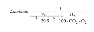
Lambada = 1.20 for instance means that there was 20% air excess where the gas analysis was made.
From the total combustion air it is necessary to subtract the various sources of false air, including primary air, which do not come from the clinker cooler.
The most complicated case is when there are two combustion process in series, such as ILC precalciner kilns.
Estimation of the secondary air requires a measurement of O2 and CO2 percent in the kiln tube exit. From this the lambada value can be calculated and hense Lcom .
Not all of this air has come from the cooler. The primary air, including transport air for coal meal (if any), must be measured and subtracted. Further, false air entering at the kiln outlet seal between kiln tube and kiln hood and through gaps in the kiln hood, must be subtracted.
If the probe sampling the gas after the kiln tube is not located inside the kiln tube, but rather in the riser duct, false air entering through the kiln back end seal must also be subtracted.
The tertiary air can be determined in a similar way. Lmin for the total amount of fuel burned in kiln and calciner. O2 and CO2 after the calciner are measured, and the lambada is calculated. The total amount of combustion air is calculated.
From this must now be subtracted secondary air from cooler to kiln, primary air to kiln burner, false air at kiln hood/outlet seal, false air through back end seal, primary air/transport air calciner, false air in calciner and false air in tertiary air dust trap. If O2 and CO2 analysis are not made immediately after the calciner but after the top cyclone, false air in the cyclone preheater including air from pneumatic kiln feed transport (if any) must also be deducted.
Cooler losses are usually measured and calculated according rules laid down by the German makers association VDZ, which use ambient temperature as the reference. When calculating the recuperation efficiency. VDZ assumes a clinker temperature of 1450 oC and nil dust circulation between kiln and cooler. The latter can have a huge influence on the actual cooler loss. VDZ further does not take into consideration that practically all mechanical energy put into cooling fans has been converted into heat when the air leaves the surface of the of clinker bed with zero pressure and velocity. The latter can be eliminated if the temperature of cooling air is measured on the pressure side of the fans.
Fig. 35 shows how the cooler loss and percent heat recuperation vary as a function of the amount of recuperated air; the more recuperated air, the lower the cooler loss and the higher the recuperation efficiency.
Case Study :
A well working simple 4 – stage preheater kiln without calciner has a heat consumption of 780 kcal/kg. It runs with 10% of primary air and an amount of excess air in the kiln of 15%. It can then be calculated that the secondary air is 1.155 kg/kg of clinker. Often the combustion air is lower, because there is more primary air. The false air at the kiln hood seal and through other openings in that area can also reduce the total amount of combustion air taken from the cooler. 0.85 to 1.00 kg/kg of combustion air is seen many places.
With the curves in fig. 35 we can define a new value to characterize the heat recuperation ability of a cooler and find a way to compare coolers in different kiln systems. If we have a cooler with 0.95 kg/kg of combustion air from the cooler and a cooler loss of 145 kcal/kg, we can see that the standard amount of combustion air of 1.115 kg/kg, the standard cooler loss would have been 118 kcal/kg, what we can call the standard cooler loss
Another cooler is working with 1.25 kg/kg of combustion air from the cooler and has loss of 127 kcal/kg. The standard cooler loss becomes 140 kcal/kg
We can see that even if the actual cooler loss of the latter cooler is less than that of the former, its heat recuperation ability is less, and it should be possible to improve it in relation to the first cooler.
Calculation of Cooler Loss
Fig. 34 defines the system boundaries for the cooler and shows the heat flows into and out from the system.
From above we have just defined how to calculate the amount of secondary air and tertiary air.
The dust circulation between kiln and cooler is very difficult to measure. Theoretically it can be calculated from sieve analysis of clinker taken after the kiln and after the cooler, but as the clinker are segregated when leaving the kiln it is extremely difficult to take a representative clinker sample at this point. Normally, the dust circulation must be estimated. From a kiln with a CFG cooler the dust circulation is app. 2 % and in a clear kiln with a traditional cooler it is 4 – 8 % In a dusty kiln it can be as high as 25 – 35 %.
All temperature can be measured with reasonable accuracy except the secondary air temperature. There is not temperature homogeneity in the kiln hood, and the radiation from the clinker is very intense. The amount of heat in the secondary air and thereby the temperature must be calculated as a difference in the heat balance for the cooler.
The specific heat for clinker and air can with good accuracy be calculated as temperature functions according to the following general expression :
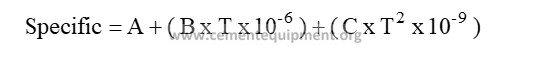
Table 1 gives the values for A,B and C for the most common elements known from the cement factory.
| Element | A | B | C | |
| 1 | CO2 | 0.196 | 118 | -43 |
| 2 | H2O Vapor | 0.443 | 39 | 28 |
| 3 | N2 | 0.244 | 22 | 0 |
| 4 | O2 | 0.218 | 30 | 0 |
| 5 | Air | 0.237 | 23 | 0 |
| 6 | Raw Meal | 0.206 | 101 | -37 |
| 7 | Clinker | 0.186 | 54 | 0 |
| 8 | Coal (30% vol.) | 0.262 | 390 | 0 |
| 9 | Oil | 0.420 | 0 | 0 |
Table 1
The electrical energy added to the cooling air fans will to a high degree be transformed into heat in the cooling air. It will result in an increase of the cooling air temperature by 5 – 18 oC depending upon the fan pressures.
In table 2 is shown an example of a cooler heat balance after retrofit of total first grate to the CFG system
Cooler Heat Balance
Reference temperature = oC
| Heat Input | Kg/kg | oC | Kcal/kg* oC | Kcal/kg |
| Clinker | 1.000 | 1450 | 0.264 | 382.8 |
| Dust (2%) | 0.02 | 1450 | 0.264 | 7.7 |
| Secondary air | 0.370 | 20 | 0.237 | 1.8 |
| Tertiary air | 0.730 | 20 | 0.237 | 3.4 |
| Excess air | 1.700 | 20 | 0.237 | 8.1 |
| Power consumption | 4.9 * 0.86 * 0.85 | 407.4 | ||
| Heat output | Kg/kg | oC | Kcal/kg* oC | Kcal/kg |
| Secondary air | 0.370 | 1245 | 0.265 | 122.5 |
| Tertiary air | 0.730 | 878 | 0.257 | 164.7 |
| Dust | 0.02 | 1200/750 | 0.254/0.227 | 4.7 |
| Excess air | 1.700 | 222 | 0.242 | 91.3 |
| Clinker | 1.000 | 85 | 0.191 | 16.2 |
| Surface loss | 8.0 | |||
| 407.4 | ||||
The secondary air temperature is calculated as difference in the heat balance.
For the VDZ cooler loss applies, Ref. Temp. ambient :
| Cooler loss | Kcal/kg |
| Clinker from cooler | 16.2 |
| Clinker at amb. Temp. 0.189 * 20 | – 3.7 |
| Excess air out | 91.3 |
| Excess air in | – 8.1 |
| Surface loss | 8.0 |
| 103.7 |
For the total cooler loss applies, Ref. Temp. oC
| Kcal/kg | |
| Clinker from cooler | 16.2 |
| Excess air out | 91.3 |
| Surface loss | 8.0 |
| 115.5 |
The standard cooler loss can be found by use the table fig. 23
Standard cooler loss 98 kcal/kg
The cooler efficiency is according to VDZ defined as the heat absorption of the combustion air divided by the maximum possible heat relased by the clinker. This calculation must be made disregarding the dust circulation between kiln /calciner and cooler.
The Heat Absorption of The Combustion Air Can Be Calculated as :
| Kcal/kg | |
| Clinker from kiln | 382.8 |
| Clinker from cooler | – 16.2 |
| Power to fans | 3.6 |
| Excess air out | – 91.3 |
| Excess air in | 8.1 |
| Surface loss of cooler | – 8.0 |
| 279.0 |
Maximum Heat Release From Clinker :
| Kcal/kg | |
| Clinker from kiln | 382.8 |
| Clinker at amb. Temp. | – 3.7 |
| 379.1 |