Contents
EVERYTHING YOU NEED TO KNOW ABOUT CEMENT KILN MAINTENANCE l MOST COMPREHENSIVE MANUAL IN THE INTERNET |
Chapter 1 GAP MEASUREMENT (Clearance) AND DISPLACEMENT (Control of Clearance) BETWEEN THE KILN SHELL AND TIRE (Kiln Tires).
1.1 OBJECTIVE AND SCOPE
The objective of this measurement is to count with the necessary information to control displacement and clearance between the kiln tube and tires due that it is fundamental for the refractory life as well as for mechanical conditions.
This is a control requiring a lot of caution, and the recommendation is to check at least once per shift.
1.2 METHOD BASIS OR FOUNDATION
There are kilns with tires that due to their design are fixed; i.e., they do not have sliding between the kiln tube and tire, but in the FLS kilns (F. L. Smidth) rolling rings of “floating” single type or “migrating” type are used, with certain diameter difference between the kiln tire and the kiln shell (support blocks).
The kiln tube and the rolling rings are dimensioned so that D internal diameter, of kiln tire, is a little bit bigger than the d kiln tube external diameter, measured in support blocks (or in the kiln tube). The diameter difference is necessary considering that the thermal expansion is a little bit bigger than the kiln tube.
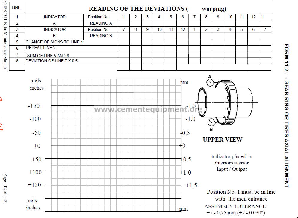
The absolute diameter difference, i.e., the diameter difference between a circular kiln tire and a circular kiln shell, is named 2s. See Figure number 1.1.
The diameter difference provokes, during the kiln rotation, a relative movement between the kiln tire and the kiln shell due to the different expanded lengths of both supporting faces.
The kiln tire movement, regarding the kiln shell, is named kiln tire displacement.
1.2.1 Importance of Clearance
It is important that the clearance between the kiln tube and the kiln tire is maintained within certain values obtained by experimentation.
If the kiln tube temperature is suddenly increased, so that the temperature difference between the kiln tube and the kiln tire is substantial, perhaps the clearance between these becomes null or negative. This way represents a possible choking between the kiln and the kiln tire. In case the choking is very pronounced, a permanent deformation called “constriction” (or trumpet) will be produced in the reinforced kiln shell of the kiln tube.
The risk of this situation is higher in the kiln tires, above and below the calcinations zone. Consequently, it is important that the relative displacement between the kiln and the kiln tires is controlled.
In case of producing permanent deformations on the kiln tube, this can result in, that a diameter extended difference involves difficulties in coating, with the consequent need to reduce the clearance between the kiln tires and the support blocks for the ring due to supplements placed below the blocks.
In order to protect the rotary kiln against deformations and / or damages in coating, produced by overheating during service, it is necessary to control strictly and perform, if possible, service corrections to maintain the diameter difference, between the kiln and the kiln tire, within an acceptable level, so that the ovality can be maintained within the admissible maximum and minimum limits.
A control of the current diameter difference, during the kiln service, is made in the simplest and most accurate mode in order to measure the kiln tire displacement, the kiln tube relative movement regarding the kiln tires.
1.2.2 Kiln tire displacement Measurement.
As previously mentioned, the supports are built so that there will be in the hot kiln a diameter difference from 0 to 3 mm between the kiln tube and the kiln tire.
The diameter difference, the clearance between the kiln shell and the kiln tire, provokes, as indicated, a relative movement between these two components.
The theoretical diameter difference, 2s, produces a relative movement as follows:
Vt = . ( 2RL – 2 RO ) RL = Internal radius
RO = External radius
Vt = . 2s
The relative movement or displacement V, between the deformed kiln shell and the kiln tire, according to acquired experiences will be, 1 1/2 – 2 times the upper clearance d (gap). When dealing with small holes, it will be 1 1/2 times and 2 times in big size kilns.
The theoretical and real displacement of kiln tire, are in reality the same, whatever the deformation is.
It is not possible measuring the diameter difference in a hot kiln, but, considering that the kiln tire displacement is a function of the diameter difference, this can be indirectly controlled by the kiln tire displacement confirmation.
1.2.3 Causes of kiln tire clearance reduction
A kiln tire in cold status is never fixed seated over the kiln. The technical reasons related to mounting explain the need to have certain clearance, so that the kiln tire can move along the kiln.
With the purpose to consider the variable thermal expansions of the kiln shell and kiln tire during the heating period; the kilns suppliers calculate both diameters so that the clearance between the kiln tire and kiln, at service temperature, adopts a minimum value. It would be ideal that the kiln, in hot status, would exert certain pressure over the kiln tire, without being subject to a contraction. This would naturally demand that the temperatures used for calculation would be really reached during the service. It is confirmed, based on experience, that it is practically impossible to anticipate the calculation of the temperatures profile related to a rotary kiln shell.
There is always a danger for the kiln when the kiln shell expands with a higher speed than that of the kiln tire. It is easy to understand that this happens when a coating damage occurs under the kiln tire. But it is not clear, on the other hand, a too quick heating condition, i.e. a start within a record time, can also have serious consequences. In this case, the kiln tire is relatively cold and the kiln shell is quickly heated, so that permanent deformations can occur due to the kiln shell contraction. In such cases, the kiln tire internal heating can lead to an inadmissible increase in the kiln tire clearance.
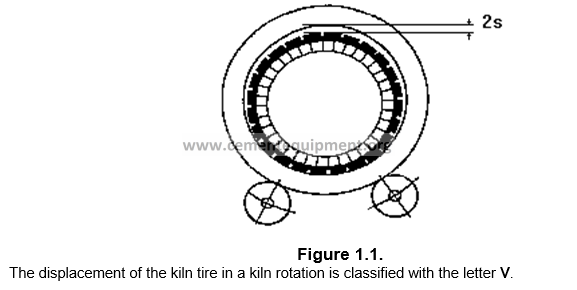
Figure 1.2 shows the temperature development of the kiln tire and kiln shell during a kiln facility-heating period. t máx. is the maximum temperature difference, which can occur between the kiln tire and the kiln shell.
Temperature curve of kiln tire and kiln shell during a kiln-heating phase
A kiln shell permanent contraction will be produced below the kiln tire when the thermal stress T for a kiln shell impaired expansion exceeds the elasticity limit F.
sT = E . t . t max < F
This can be the case when the required clearance in cold status sth is little or zero.
In the same way, whenever the maximum temperature difference t max is too high due to an excessively fast heating situation.
1.3 METHOD DEVELOPMENT
1.3.1 Equipment and tools to be used
F.L. Smidth supplies automatic equipment for kiln tire displacement surveillance and control. In case that such equipment is not available, it is possible to measure the kiln tire displacement manually.
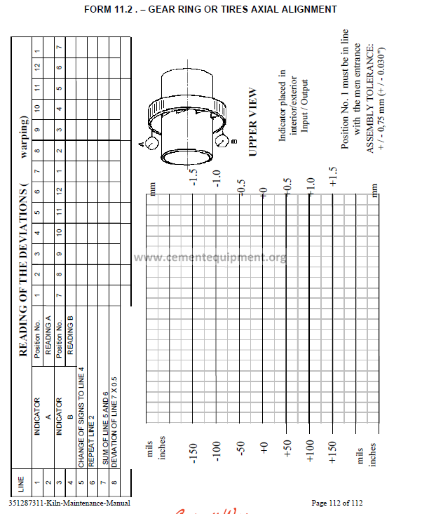
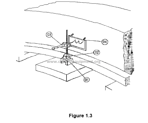
One of the most utilized methods in Cemex is the use of Displacement and Gap Meter (Figure 1.3). This measurement appliance is composed by a bracket (02) that, through a magnetic base, is placed on one of the support blocks. The bracket supports a recording needle (03), under a spring and in horizontal position, pressed against a piece of paper that is, through the usage of adhesive tape, fixed to a plate (04), that in turn, is fastened to the kiln tire by magnetic blocks.
Additionally the measuring can be made by a manual method, which is described in the procedures section.
1.3.2 Periodicity
The measuring operation of the kiln tire (tire) displacement and gap is a control requiring the most caution, and the recommendation is to check it at least once by shift.
When dealing with kiln starts, the measuring operation must be more intensive, i.e. measuring two or more times per shift.
1.3.3 Procedure, calculation methods and results
1.3.3.1 By the displacement and gap-measuring appliance.
Placing coupled marks in the kiln tire and in the kiln tube can perform, in a very easy way, the simplest kiln tire displacement measuring method. Whenever the kiln has been spinning, for example, 10 rotations, the displacement between marks is measured, in this way, the average displacement calculation is possible.
The clearance can consecutively be found when dividing V by 1.5 – 2, i.e.:
V
= ————-
1.5 a 2
If the displacement average V is divided by , the result is :
V/ = 2s, it means
The theoretical clearance in the circular kiln tube / kiln tire.
1.3.3.2 Using the displacement and gap meter.
A method even more practical for measuring V and , utilized by CEMEX, is performed with a single appliance named: displacement and gap meter, shown in Figure 1.3, described as follows:
The appliance is placed as illustrated in Figure 1.3 and during the kiln rotation; the recording needle will draw a curve, as illustrated in Figure 1.4, corresponding to the kiln base where the kiln is to be measured.
The curves shown are equivalent to 5 kiln turns or rotations illustrated in Figure 1.4, the values V and S can be directly measured in the curve.
As previously mentioned, it is important that the clearance between the kiln shell and the kiln tire is maintained within determined values.
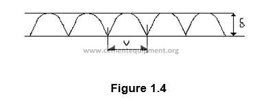
If the recording needle, during the kiln starting process, begins to draw smaller and smaller curves, means that V and S tend to null value, and it can be necessary to participate in order to prevent “constriction”.
1.3.4 Interpretation of results.
Gap Adjustment
As previously mentioned, the big deformations are observed in the zone of the kiln tires having an important clearance.
In order to reduce deformations, it is necessary to reduce the kiln tire clearance by lower shimming of kiln tires wear pads, provided that it is constructively possible (kiln tire wear pads are screwed).
In such case, the thickness of plates to be placed must be determined.
The safest method for this purpose is the following:
– Daily determination of a relative movement U and / or during a period sufficiently long (3 months).
– The minimum value U and / or V occurring within this period must serve to determine the mean clearance of the kiln tire.
– The supplementary plates thickness is obtained from the mean clearance of the kiln tire sth and / or .
U
sth = ——–
– As a safety factor regarding the big thermal expansions, the supplementary plates thickness will be dimensioned so that the clearance in service status is within the order of 3 mm.
Therefore, the thickness for the supplementary plates is the following:
sth – 3
tB = ————- mm
2
1.3.5 Safety aspects
In order to measure the kiln tire gap and the displacement, the activity must be executed with the kiln running and in hot condition, as previously mentioned, thereby special caution and attention must be paid to prevent damage by burning or by touching the equipment in motion.
1.3.6 Condemning or permissible limits
The relative movement or displacement V, between the deformed kiln shell and the kiln tire, must be according to the acquired experiences, 1 1/2 – 2 times the upper clearance d (gap). When dealing with little kilns, it will be 1 1/2 times and 2 times for big size kilns.
1.4 COMMENTS AND OBSERVATIONS
As previously mentioned, it is very important to have kiln tire gap and displacement control, this procedure is therefore classified as general observance and mandatory.
1.5 ATTACHMENTS AND USED FORMS
The form used to record information is free, it means the wanted information can be utilized according to each plant needs.
1.6 REFERENCES
– Control of clearance between the kiln tube and the kiln tires,
Manual F.L. Smidth 19124-01.
– Recommended Procedures for Mechanical Analysis of rotary kilns,
Book of Robert P. Chapman (Fuller Company).
Chapter 2 DEFORMATION AND OVALITY
2.1 OBJECTIVES AND SCOPE
The main objective pursued with the deformation and ovality control is to avoid an excessive wear on the kiln coating or that coating bricks fall down, to meet this goal, the ovality must not exceed certain service status limits, the measurements are made with the kiln in operation.
2.2 METHOD BASIS OR FOUNDATION
2.2.1 Radial deformation and its repercussion
Each rotary kiln in service shows through time certain radial deformations, especially in the kiln tires zone, it means, the kiln shell adopts various curvature radius during a complete turn.
The deformations can be subdivided into:
– Deformations of kiln tires in the rollers zone, coming from both reaction forces Q/2.
– Deformations of kiln shell, or crushing in the highest point, caused by the clearance between the kiln shell and the kiln tire.
These deformations are transferred to the kiln coating and therefore influence essentially its duration. Due to the constant variation of kiln shell curvature radius, the so-called crushing process is produced during a spin.
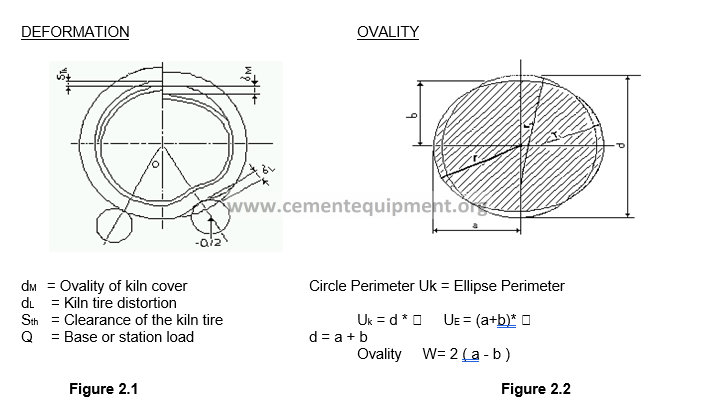
For this reason the kiln coating bricks are strongly requested in the side areas, with the potential consequence of an elevated wear or bricks falling down. In order to prevent these difficulties, it is essential to know these deformations magnitude, by measuring them regularly to take the necessary steps on time. See Figure number 2.1.
2.2.2 The rotary kiln ovality
The term ovality is applied to the dimension or deformation degree. If is considered that the kiln circular shell adopts the elliptical form when deforming, the ovality can be defined as twice the difference between both semi-shafts (axis). See Figure number 2.2.
Ovality W = deformation degree.
Previous Condition:
Periphery of ellipse UE = Periphery of circle UK
UE = (a + b) UK = d .
Definition:
W = 2a – 2b = 2(a – b)
In order to compare among themselves the ovality values for different sizes, the ovality is shown in % of kiln internal diameter (kiln shell plate).
2.3 METHOD DEVELOPMENT
2.3.1 Equipment and tools to be used
The radial deformations of a kiln shell in service can be recorded through any measuring appliance for deformations of kilns in usage:
– Measuring Appliance “Shell test” with Holderbank design
– Measuring Appliance “Ovality Beam” with Phillips design
2.3.1.1 Shell test appliance
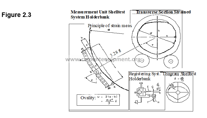
The measuring principle of this appliance can be described in the following manner. See Figure number 2.3.
A bridge (A), where a magnet series (B) has been provided on every end, is attached to the rotary kiln in vertical position to the central shaft. The bridge covers a circle segment with a basis length 1 = 1 m. and an arch height h. The recorder (C) is placed in the beam center.
During the measuring , its feeler’s point (D) must rest over the kiln shell, in order to obtain the height h change transmission (caused by the curvature radius r change) to the pencil (E9. The pencil is moved within a pantograph guide transmitting the deviations h in a 1:15 rate.
The polar diagram disk (F) is screwed to the pendulum disk (G) in the recorder shaft. This is permanently maintained in the same perpendicular position due to the weight (H). In this way a relative movement is produced between the pencil and disk of diagram. This movement remains synchronized with the rotation angle variance.
After a revolution in the diagram a closed line appears. This line is the polar representation of the height h change in function of the rotation angle , meaning a graphic geometrically similar to the deformed section of the kiln (Shell test diagram).
These diagrams can be evaluated in the first place qualitatively.
The deviation regarding the circular form allows forming an idea about the deformation. The deformations can be located by the curve position regarding the polar coordinates system. The kiln vertical shaft corresponds to the diagram vertical shaft, which is identified through a small hole provided above the coordinates center.
The appreciation results very easy due to the polar representation, as the curve constitutes an image geometrically similar to the kiln transversal section deformed.
It is possible to recognize quickly, for example, if a big deformation exists in the kiln tires (rollers) zone (this is the case when the kiln tire is not sufficiently rigid), or when the kiln shell deformation is on the highest point, in this case there is a too big clearance of the kiln tire.
The utilization of this method does not allow a real measuring in the sense of absolute values. What is recorded is the variation of arch height h according to the polar system, being only interesting the maximum deviation or maximum difference between both semi-axis of the ellipse contained in the diagram. For the diagram evaluation the following concepts are important:
– Deformation degree = ovality w, defined as twice the difference between both semi-axis of the kiln transversal section, deformed in ellipse form.
a = big semi-axis
W = 2 (a-b)
b = small semi-axis
– Deformation Dimension , the biggest difference between both semi-axis of the ellipse contained in the diagram.
The mathematical relationship between the ovality W and deformation dimension is obtained based upon the following formula deducted by G. Rosenblad.
W = 2 (a – b) = 4/3 * d2 * (mm)
where: W = Kiln ovality
d = External diameter of kiln shell (m)
l = Base length 1 m.
= Measuring maximum deviation (mm)
Wr = W / di * 100
where: Wr = Relative ovality ( % )
di = Kiln internal diameter
2.3.1.2 Ovality Beam Appliance
The kiln shell ovality is measured more easily by using the Ovality Beam electronic appliance.
The appliance is quite similar in construction to the Shell test, but the main difference consists in the handling of measuring, instead of plotting it directly into a diagram, it is recorded in an electronic recorder, as illustrated in Figure 2.4.
The recorder stores the entire bar positions. And the maximum and minimum values are utilized to determine .
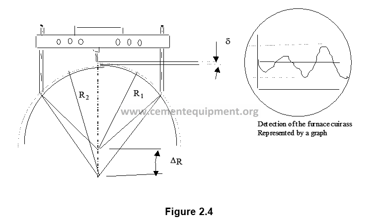
This value can be mathematically related to the maximum change in kiln radius. This is shown as R in Figure 2.4, and is equal to R2 – R1, where R2 is the highest radius of the deformed kiln during its revolution, and R1 is the lowest radius of the kiln deformed in the same revolution, from this the following deduction is obtained: W = kiln ovality
W = 2 (a-b) a = big semi-axis = 2 R2
b = small semi-axis = 2 R1
The mathematical relation between ovality W and deformation dimension is obtained based on the following formula deducted by F. G. Rosenblad.
W = 2 (a – b) = 4/3 * d2 * (mm)
where : W = Kiln ovality
d = Kiln shell external diameter (m)
l = Base length 1 m.
= Measuring maximum deviation (mm)
and Wr = W / di * 100
where: Wr = Relative ovality ( % )
di = Kiln internal diameter
2.3.2 Periodicity
The kiln shell ovality measurement must be made once in a year, or before depending on the deformation and displacement measurement results.
2.3.3 Procedure, calculation method and results
2.3.3.1 Preparation Steps
The kiln rotary deformations reduce as long as the kiln tire distance increases. Therefore, the Shell test measurement must be performed always close to the kiln tires (kiln tire shell), as much as possible on both sides. Whenever the protection shields against heat are mounted too close to the kiln shell, a removal of them will be necessary.
The kiln must be in steady operation conditions for all the measurements to be taken. And all the readings must be taken (at the entrance or exit) in the same position for future reference.
In order to be able to get a clear idea about the deformations dimensions, the measurement of every drawing must be performed on three points located in casing lines displaced in 120, see Figure number 2.5. Also for later measurements it is the recommended to use always the same drawings and measuring points.
– Mark with chalk lines all along the measuring points, precisely on those points where is the measuring appliance feeler’s tip.
– Every time it is necessary, clean the support points of the magnet with a wire brush.
2.3.3.2 Measuring Procedure with the Shell test appliance
It is required to fix the diagrams disk in a manner that it is fastened against spinning, with the coordinates network at the inscribing pen side.
The small hole in the middle, is used for disk fastening, points out to it, over the diagram, the highest point (kiln shell highest point) of the measured transversal section.
The appliance will be prepared now for measuring in the following way, or it will be adapted to the kiln diameter.
Drop the sleeves in form of a star and displace the magnet carrier so that the inscribing pen is located in horizontal position when the appliance is placed. The inscribing pen must be fixed in the first notch (disconnected position).
– At the same time of kill spinning, place the measuring appliance in a marked position (point 1) and confirm if the appliance adhesion force is sufficient. The diagram image side (coordinates network) must indicate always in the same kiln entrance direction.
– Place the inscribing pen, through the precision adjustment screw, so that the three curves of a measuring plan (points 1, 2 and 3) have enough space in the same diagram. For the first measuring, place the inscribing pen slightly upwards, for the second measuring in the middle and for the third measuring slightly downwards.
– In the disconnected position of the recorder, the appliance must remain disconnected during two or three kiln turns, in order that the feeler’s tip can extend because of the kiln shell temperature, which does not influence the diagram.
– Through a slight pressure, carry the inscribing pen till the second notch, so that the inscribing pen is supported over the diagram.
– After one turn (measuring time), remove the inscribing pen to the disconnected position, by pulling at the pulsating button.
– Remove the Shell test appliance, fix it in the next measuring point and proceed in the same way as before.
– Once all the measuring operations are finished, place the protection plates over the magnets.
2.3.3.2 Measuring procedure with Ovality Beam Appliance
The measuring sequence is similar to the described in the previous point by utilizing the Shell test appliance, with the difference that the data are electronically recorded, and these are transferred to a computer, which will provide us with a graphic that practically is the extended ovality curve as illustrated in the right side of Figure number 2.4.
The readings of every kiln base are used (the appliance can store data for maximum 8 bases). These readings are stored separately from the kiln running parameters.
The detailed operation is not explained here because it is too long; therefore it will be necessary to refer directly to the appliance manual.
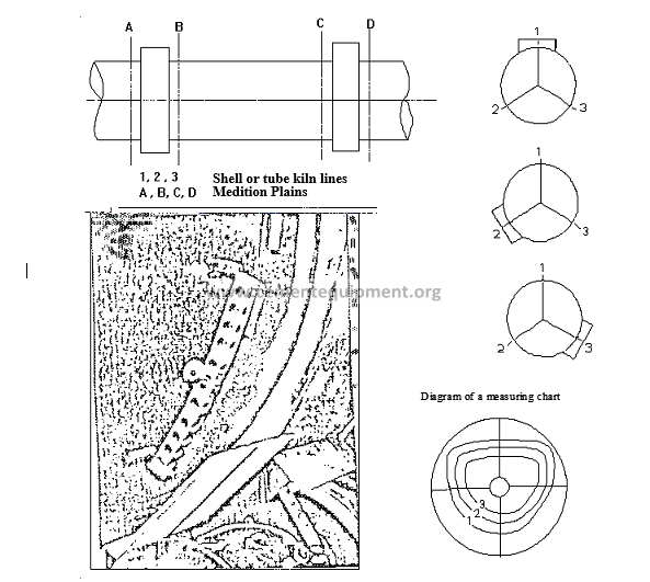
Figure 2.5
2.3.4 Interpretation of results
2.3.4.1 Results evaluation
The evaluation through calculation, this means that the ovality calculation from the Shell test diagram or the Ovality Beam graphic, is performed based on the following relations:
4 * d 2
Absolute Ovality = wa = ———– * mm
3
4 * d 2
Relative Ovality = wr = ———– * * 100 %
3 * dN
= ’ / 15 (mm) measured in the Shell test diagram.
d = kiln shell external diameter (M), (dN + 2t)
dN = kiln shell internal diameter (mm)
– In a kiln with an ideal behavior, the three ovality values measured in a drawing would be super positioned. Nevertheless, these values are slightly deviated between them in practice, as there are weak points located on the kiln cover.
2.3.4.2 Shell test
The Shell test diagram, as a polar representation of the height variations for the h segments, offers the advantage that it also allows, immediately, a qualitative evaluation of the measurements by people with little experience, as the diagram represents an geometrical image similar to the kiln deformed transversal section (elastic line), with the only difference that the radial variations are recorded with an increase of 15 times.
In order to appreciate the deformations diagram, it is essential to consider them correctly.
If the coordinates network indicates, during the measurement in the kiln entrance direction, the diagram must be observed during its kiln entrance side appreciation, in order to match the corresponding sides. The small hole in the diagram disk must be located in the12 hours position, as this position marks the vertical axis, as well as the highest point of the measured transversal section.
Data legend:
dN = Kiln nominal diameter (internal diameter).
d = Kiln shell diameter.
= dN + 2 . t
t = Plate thickness.
wL = Ovality calculated of kiln tire.
jL = Kiln tire inertia moment
w = Ovality measured with Shell test appliance.
U = Relative movement.
Sth = Kiln tire clearance.
2.3.4.3 Ovality Beam
The Ovality Beam appliance generates a Cartesian graphic in X-Y format. This represents the radial deformations occurring during the kiln rotation, in a turn, as illustrated (exaggerating the deformation) in Figure number 2.6
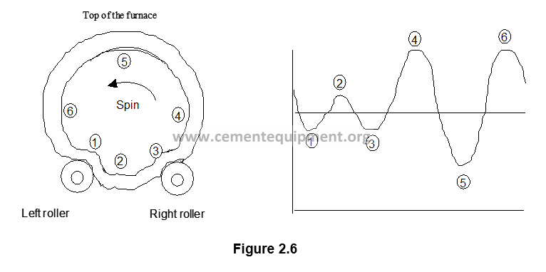
The trace begins with the recording of the first data at the kiln side when spinning downwards, just before reaching the first roller.
The position 1 of the curve represents the reference point #1. The position 1 coincides when crossing through the first roller. The depression in the curve is caused by the support roller reaction over the tire. The ovality W is a tire ovality transfer over the kiln shell. The tire is deflected by the roller and this to the tire, and this in turn to the kiln shell, causing a reduction in the kiln shell curvature.
Immediately after the first roller, the bar passes to position 2, which is the kiln lower central part. Between the rollers, the shell curvature is appreciated as normal.
In position 3, the bar reaches the second roller. And the kiln reaction is similar to the position 1. Again the kiln shell is crushed, and the curvature is reduced.
From position 3, the ovality appliance passes to the kiln ascending lateral upper part. The kiln curvature is increased at its maximum, just in the vertical tangent point.
The position 5 is the kiln top. The kiln shell is crushed in this position, and the curve indicates a curvature reduction.
The position 6 is a mirror of position 4, excepting that it corresponds when the kiln goes downwards.
The maximum and minimum points are used to calculate the ovality.
2.3.5 Safety aspects
It is always dangerous to work close to a rotary kiln. Due to that it is necessary to take the ovality measures close to the running kiln, it is important to put on the appropriate clothing, and use safety goggles, safety shoes, gloves and safety shields.
Make sure that the measuring bar whether is Shell test or ovality beam or that everything is free around the shell. The upper half must be inspected to prevent obstructions. It is possible that there is no view from the base upper part, and the remarks must be made from an other point of view.
The shell area where the bar magnets are located, must be polished with a wire brush in order to assure their correct fastening.
Avoid the magnets placement over the kiln shell welding cords as it can lead to incorrect readings.
2.3.6 Condemning or permissible limits
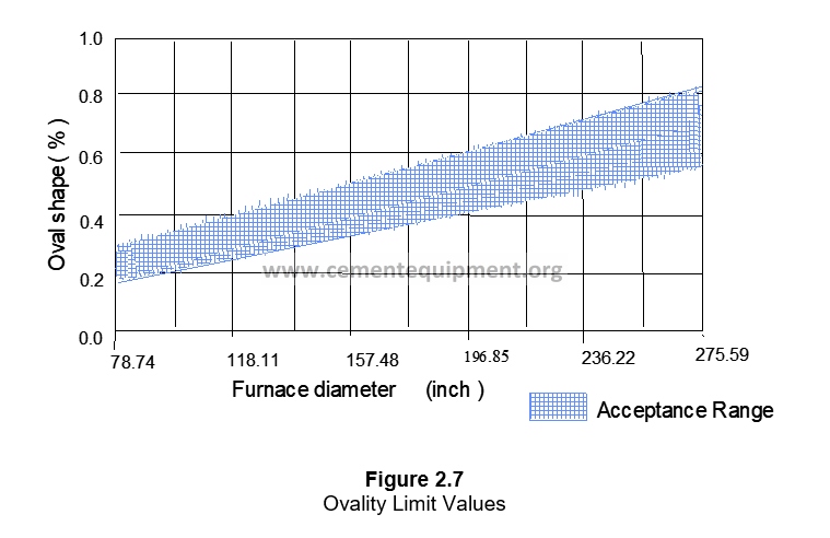
The determination of an ovality limit value, i.e. a limit from where it is possible that coating damages can follow, and it is difficult and depends on the kiln size and the existing coating conditions. Figure number 2.7, shows the existing relation (obtained from experience) between the admissible ovality and the kiln diameter in good coating conditions.
In a ø 3.5 m kiln the approximate limit is 0.3%.
In a ø 6.0 m kiln the approximate limit is 0.5%.
When the ovality limit value does not exceed the corresponding kiln diameter, the coating request will be insignificant as consequence of the kiln shell deformation.
2.4 COMMENTS AND OBSERVATIONS
The ovality measurement is an extremely important factor that must never be overseen for the good preservation of a rotary kiln.
Thanks to experience, there are data available that help preventing from major damages, as the ovality graphics can determine the following:
– Kiln cracks
– Excessive clearance between kiln tire and shell
– Kiln misalignment ( run out )
– Rollers misalignment (different deformations on both rollers)
– Tire with over or sub load
2.5 USED ATTACHMENTS AND FORMS
The used format is free, although basically a reliability module must be followed at the kiln.
2.6 REFERENCES
– Manual of Holderbank Shell test
– Users guide of Phillips Ovality Beam
– “Detecting and Measuring Deformations of Rotary Kilns” by F.G. Rosenblad,Rock Products.
Chapter 3 TIRES AND ROLLERS DIAMETERS MEASUREMENTS (In cold and hot environment).
3.1 OBJECTIVE AND SCOPE
This procedure indicate us the form of higher precision measuring and count with the exact diameter of rollers and tires (kiln tires), in order to determine their wear based upon their original dimensions, and in turn to utilize such measures for other calculations such as alignment, etc.
3.2 METHOD BASIS OR FOUNDATION
3.2.1 Support rollers and tires tracks (kiln tires) wear.
The wear and deterioration of the rollers and tires surfaces can be produced due to:
– Misalignments.
– Tires warping, due to kiln deformations.
– Excessive axial loads on the support rollers.
Due to these causes, the tracks of rollers and tires lose their cylindrical form, that is the condition of a correct support and load on the bearings and axial device. Therefore it could be eventually necessary to rectify the tire tracks in order to establish the cylindrical surfaces.
For this purpose, currently exist devices for tire tracks rectification, with the kiln running.
3.3 METHOD DEVELOPMENT
3.3.1 Equipment and tools to be used
3.3.1.1 Measuring in hot environment
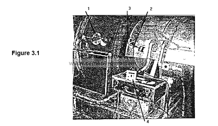
For control of tracks diameters and “cylindricity”, the measuring equipment illustrated in Figure number 3.1 is utilized.
F.L. Smidth, has developed this circumferential measuring special equipment, which offers the advantage to perform such measuring, without kiln shutdown, it means that in full production process the existing diameters as well as their “conicity” can be determined.
As it can be observed in Figure number 3.1, it is composed by some components.
A feeler and / or a movement follower wheel
02) Lens or electronic eye.
03) Magnetic fitting (magnet).
04) Electronic counter.
3.3.1.2 Measuring in cold environment
A metallic tape is utilized to measure the perimeter of rollers and tires surface.
3.3.2 Periodicity
The measuring must be made on annual frequency, or every time when the rollers measuring will be utilized as precise data, for example in the kiln alignment, etc.
3.3.3 Procedure, calculation methods and results
3.3.3.1 Measuring of diameters corresponding to rollers and tires in hot environment
This operation is performed through a direct electromechanical exploration.
As preparation to perform this measuring, it is necessary to adapt a support in form of “U” inverted, with 2 x 2 x 1/4″ as angle, on every kiln base, as it can be observed in Figure number 3.1.
In this support the follower element (01) is defined, which send the movement signal to us, this element will make contact with the roller, at the moment when this element (01) has made the contact, the spinning begins. Care must be observed to assure the follower wheel is in correct position, at 90° regarding an imaginary horizontal line, this can be made, by adjusting the 3 setscrews placed at every 120° regarding the follower wheel (01) diameter, another important point is to adjust the 3 mm. Setscrew, fixing the feeler wheel coupling and shaft in order to assure an uniform movement between both components.
It is convenient, to note that the feeler element, must be placed in three different positions along the contacting surface width, in order to get an idea about the roller conicity.
The next step is to place the element (03), magnet, with its fitting, (in the left roller, right roller and in the tire), depending on which one is being analyzed, this element is placed in the lateral face of the bodies to be analyzed, and it must be made during the first turn passing free, in order to prevent reading mistakes.
Once the above is done, place the electronic eye (02), by support with the dial indicator magnetic base; the appropriate position is when the element (03) placed in the roller and / or tire, crosses freely the magnetic eye and this one detects it as from this point the signal will begin to count the number of turns, according to the selection made in the electronic counter.
Once the previous points are confirmed, proceed to connect the electronic counter, which has a digital screen where the analyzed wheel perimeter measuring will be read, whose units are shown in mm.
This counter has a selector to elect the number of turns wanted to be analyzed, normally one turn is considered to obtain the roller or tire perimeter.
After every measuring, control must be reestablished in order to pass again the fitting (03), through the magnetic eye, the count down is restarted, repeat this operation 2 – 3 times and get an average.
Note that the circumference-measuring appliance allows obtaining the perimeter, for roller as well as for tire, thereby the following formula is utilized to obtain the diameter:
P
D = ——
3.3.3.2 Measuring method for diameters of rollers and tires in cold environment.
This is the traditional method, where a metallic tape is utilized to measure rollers and tires surface perimeter. It is necessary to mention that it is not very reliable, due to the access limitation to pass the tape and its placement along the circumference, as well as the stress applied on it in every measuring operation.
3.3.4 Interpretation of results
The most reliable measuring for rollers and / or tires diameters is the measuring applied in hot environment, as it complies with the real running conditions.
3.3.5 Safety aspects
It is always dangerous to work close to a rotary kiln. When rollers and / or tires diameters must be measured it is necessary to work close to a running kiln; appropriate clothing, safety goggles, safety shoes, gloves and safety shields must be utilized.
3.3.6 Condemning or permissible limits
Every kiln manufacturer, has a maximum or minimum tolerance in the rollers and tires diameter, but it is considered that a tire or roller has reached its service life limit, when it shows 5 % reduction in its nominal diameter, and in that case it must be replaced and send for outfitting or recovery to nominal dimension, depending on its feasibility.
3.4 COMMENTS AND OBSERVATIONS
The measuring of rollers and tires is very useful, to perform another type of kiln inspections and / or analysis, real data will be utilized.
3.5 ATTACHMENTS AND FORMS UTILIZED
The format utilized is free, although basically a log for each kiln must be maintained.
Chapter 4 MEASURING AND ADJUSTMENT OF SUPPORTING ROLLERS AXIAL LOAD(kiln tires)
4.1 OBJECTIVE AND SCOPE
The main objective pursued is to measure during the kiln running, the force of the supporting rollers or kiln tires to exercise influence in axial direction over the bearings, in order to take care about excessive loads in them which could provoke damages.
4.2 METHOD BASIS OR FOUNDATION
The supporting rollers bearings heating (support rollers) is due to very diverse causes.
The most common problems can occur when:
– The bearing is exposed to irregular axial or radial loads at abnormally high temperatures.
– Change in the geometrical forms of the shaft trunnion shaft and the bearing gland (bronze).
– The oil type utilized does not have the prescribed viscosity.
From the cited problems, the most frequent is the bearing heating due to excessive axial loads.
The axial reaction is originated when the kiln tires are not in parallel position regarding the kiln shaft or they have a divergent inclination, i.e. when parallelism does not exist between the kiln tires and the tread ring shaft. In case the axial loads exceed the allowed limits, an adjustment will be made during the running operation displacing the supporting bearings in horizontal sense.
The cited adjustment guarantees also a correct load in the retaining system and a good tread of the detention kiln tires with the ring. The wear is reduced at the minimum, as 100 % contact exists between the surfaces of ring and kiln tires.
4.3 DEVELOPMENT OF THE METHOD
4.3.1 Equipment and tools to be used
To maintain these axial loads within the permissible limits for every one of the sizes of the bearings. F. L . Smidth has developed special equipment, making possible to measure, during running, the force of the kiln tires exercising their influence in axial direction over the bearings.
The axial measuring equipment is utilized to measure the force of the kiln tires exercising over their bearings in the axial sense.
4.3.1.1 Equipment description.
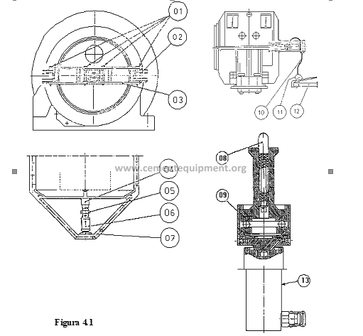
(See the figure 4.1)
The equipment for axial measuring is composed by a pressure tip screw (04), a pressure cylinder (13) and fastening pieces. The pressure tip screw is placed on the fastening pieces, which are suspended on hinges (02) of the supporting bearings box. The tip screw is activated by the pressure cylinder (13) when the latest is placed under pressure.
It is also composed by a hand pump (12), provided with a manometer (11) and connected by a hose (19) and a coupling piece to the pressure cylinder (13).
The hand pump is additionally provided with a pressure-limiting valve, which prevents, that the cylinder pressure can exceed 580 bars, which is equivalent to a force of approximately 8 tons.
4.3.1.2 Measuring principle.
The measuring has, in principle, by effect that the pressure cylinder presses the tip screw against the kiln tires shaft end, with a force opposed to the kiln tires reaction and sufficiently big to exceed the latest, so that a permanent space is produced among the pressure ring and the pressure neck in both sides of the kiln tires.
Once this condition is satisfied, these both forces are compensated between each other, and the axial reaction can be calculated through the cylinder pressure and the piston area.
4.3.2 Periodicity
The rollers pressures revision, must be made once a year minimum or every time observing an excessive heating (or tendency to it) on the bearings.
4.3.3 Procedure, calculation methods and results
4.3.3.1 Mounting
Mount the hinges (02) on all the kiln tires bearings, as illustrated in Figure number 4.1. Use the long pins of degree 5 (quality 8.8). The hinges must remain permanently in the bearings box.
Mount the shot sections (03) and the console (07) through the four 20 mm pigs (01).
Dismount the cap of the supporting bearing center.
Mount the distance tube (06) and the fastener (05) for the pressure tip screw (04).
Place the pressure cylinder (13) in the fastener, place the centering pig (08) in the hole for the tip screw, in the kiln tire shaft, and stretch the cylinder.
Mark and drill and appropriate hole exactly in the kiln tires center, if it is not provided in advance of a hole to introduce the tip screw.
Connect the cylinder with the hand pump through the hose (10) and the coupling piece.
4.3.3.2 Dismounting
Remove the pressure to the equipment, by opening the return valve of the hand pump.
Dismount the hand pump and hose.
Remove the pressure tip screw and cylinder.
Dismount the shot sections and four pigs (01), so that only the hinges remain in the bearing box.
Mount the cap with monogram in the bearing box.
Apply anticorrosive oil to the hinges.
4.3.3.3 Procedure
In general, the rotary kiln tires must be parallel to the kiln shaft, when it is equipped with hydraulic guiding device, so that a normal tread is produced, without axial reaction between the kiln tires washer and the tread ring.
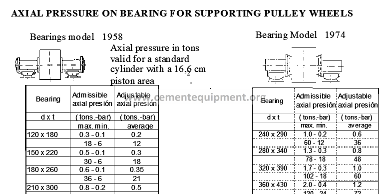
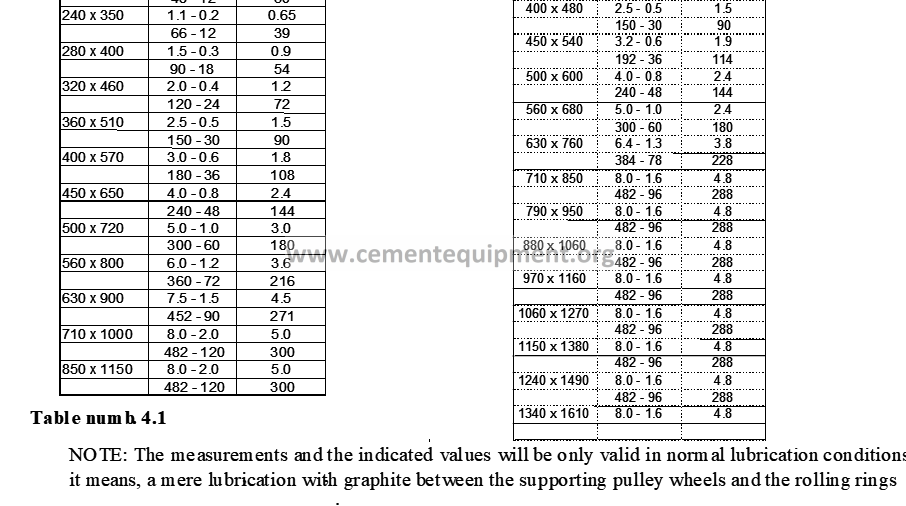
This is impossible in practice, it is necessary to orient the kiln tires so that all of them have a little tendency to press the kiln upwards. The axial reaction to be produced as consequence of this, must be within determined maximum and minimum values, for the different types and sizes of bearings, as indicated in the table number 4.1.
The axial force is transmitted to the supporting bearings through a pressure ring in the kiln tires shaft and a corresponding pressure neck in the gland. It is possible to control the sense of the axial force when verifying in which bearing there is a clearance between the pressure ring and the pressure neck of the bushing. See the Figures number 4.2 to 4.5.
The measuring of the axial forces and the kiln tires adjustment must only be made when the kiln is under normal running conditions.
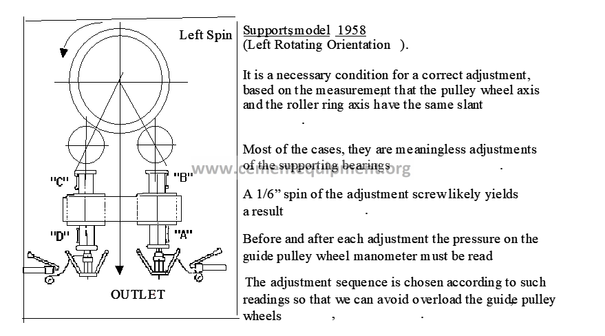
4.3.3.4 Bearings, model 1958
When dealing with this type of support it is necessary to have a clearance between the pressure ring and the pressure neck, in all the bearings oriented downwards or the bearings in the exit side of the tread ring when the kiln tires are correctly placed, it means, with a little tendency to press the kiln upwards against the entrance.
Previous to proceed with the measuring and the adjustments, a note must be made in writing which ones are the kiln tires pressing the kiln upwards, and which ones are pressing it downwards.
The pressure sense of kiln tires pressing the kiln downwards changes its direction and the measuring is performed.
This procedure is performed through a determined method, so that the guiding kiln tires are not reloaded in any moment. Read, therefore, the hydraulic pressure on the guiding kiln tires manometers before and after every adjustment.
Measuring in each one of the bearings is performed in the following manner:
Place the measuring equipment in the bearings box hinges, as described in point 4.3.3.1 (see Figure number 4.1).
Begin the measuring operation by pumping the cylinder up to the maximum pressure for the corresponding bearing size. See the table number 4.1.
In a time term of approximately 10 minutes the pressure in the cylinder will be adjusted to a value mediating among the maximum and minimum pressure, if the supporting washer is correctly adjusted. At the same time, a permanent clearance will be produced on both pressure necks of the bearings.
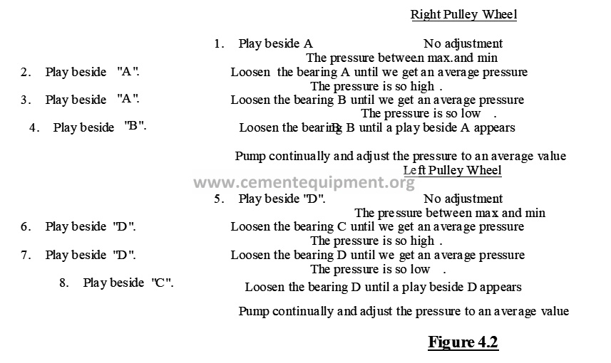
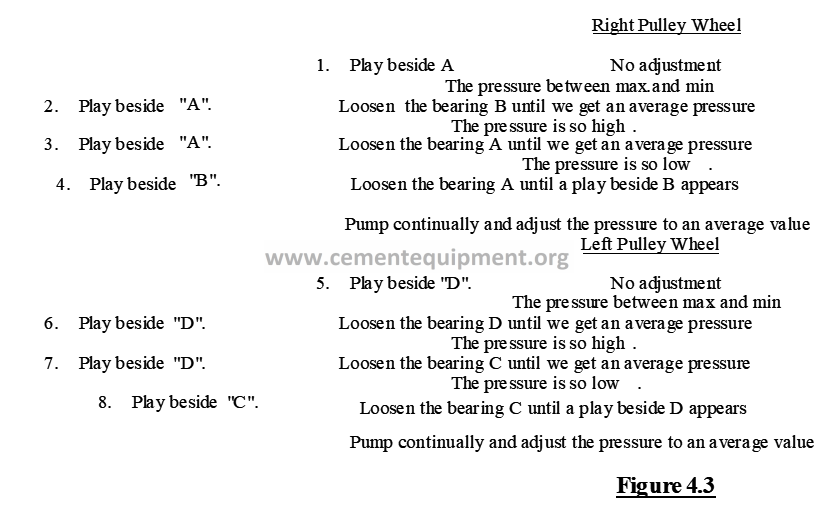
The pressure could vary a little bit during the kiln rotation due to the tread ring warping, etc., thereby a mean value of the read pressure must be available. If the marked pressure does not decrease below the maximum pressure, or if it decreases below the minimum, the kiln tires position must be modified according to the indications contained in Figures number 4.2 and 4.3.
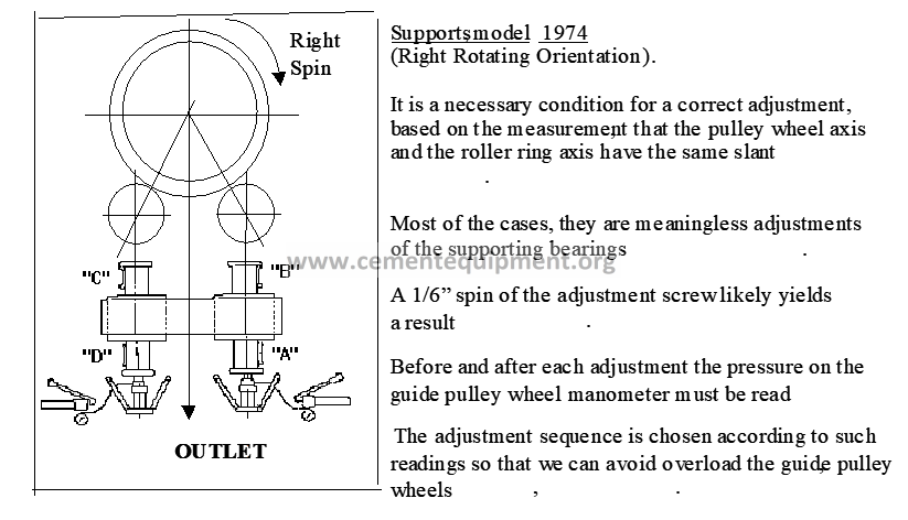
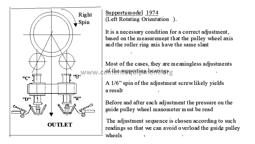
4.3.3.5 Bearings, model 1974
In this case, the measuring equipment is placed also in the bearings oriented downwards. In these bearings, where the supporting washer pressure rings are placed between the bucket and the gland, a clearance must exist between the pressure ring and the pressure neck of the gland in the bearings oriented upwards.
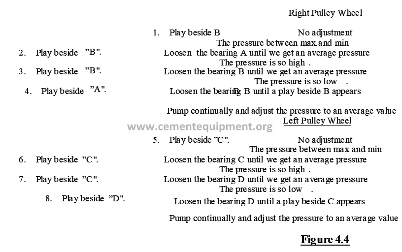
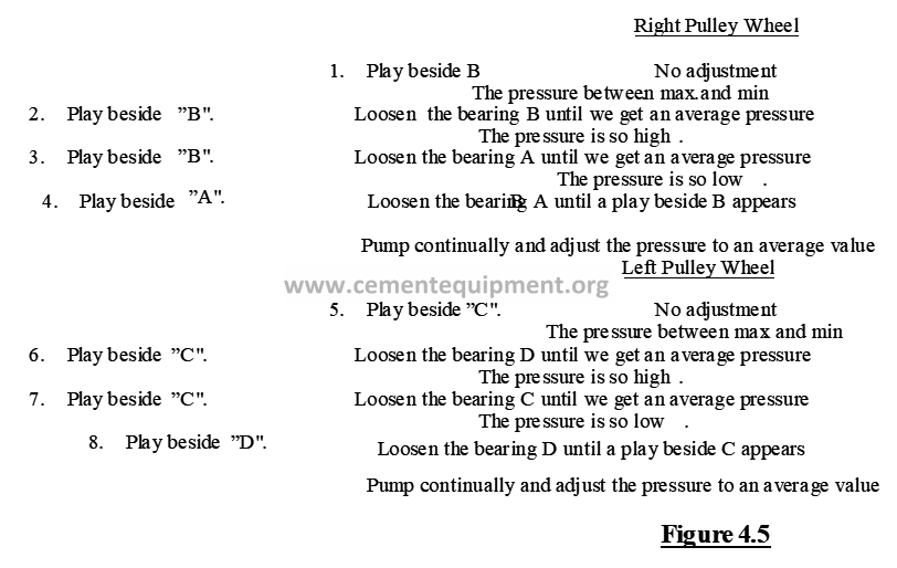
The rest of the procedure is such as described in the point 4.3.3.3. The indications concerning the corrections are located in the Figures number 4.4. and 4.5.
4.3.4 Interpretation of results
Every correction in the kiln tires position (rollers), will be based upon the indications of the figures 4.2 to 4.5, depending upon the corresponding type of support.
4.3.5 Safety concerns
It is always dangerous to work close to a rotary kiln. To measure the axial pressure of the rollers requires to work very close to an operating kiln; appropriate clothing, safety goggles, safety shoes, gloves and safety helmet must be used.
This is High-pressure hydraulic equipment ,care must be observed to never bend the hoses; additionally special caution must be taken for their conditions, as the usage of defective hoses implies a serious risk of personal injury.
4.3.6 Condemning or permissible limits
Also as in point 4.3.4, they will be based upon the indications of Table 4.1.
4.4 COMMENTS AND OBSERVATIONS
The axial measuring equipment as a whole, requires maintenance, in this case this maintenance consists of the following:
– Fill the hand pump with hydraulic oil.
– The spherical axial bearing, in the pressure tip screw, is of perpetual greasing and does not require any lubrication.
– The equipment must be mounted after utilizing it, as well as plug all the hydraulic couplings and place the equipment in an appropriate transportation case.
– The fastening pieces must be well painted with anticorrosive paint.
4.5 ATTACHMENTS AND FORMS USED
Table number 4.1, indicates the maximum and minimum values of the axial load in the kiln tires as well as an adjustment value, which is an intermediate value between the maximum and minimum values.
The tables also indicate the hydraulic pressure, corresponding to the axial loads, when a cylinder with a piston area of 16.6 cm2 is utilized.
The Figures 4.2 to 4.5, instruct how to control the kiln tires position through the placement of a clearance and the hydraulic pressure value, in addition to how to obtain the desired position for the kiln tires.
Chapter 5 MEASUREMENT AND ADJUSTMENT OF THE ROLLS INCLINATION (or support sheaves)
5.1OBJECTIVE AND REACH
The objective of this procedure is to have a good contact between rolls (support sheaves), and the tread hoops (rims),
5.2 BASIS OR SUSTENTATION OF THE METHOD
A deficient contact can be due to an incorrect inclination of the sheaves in relation to the tread hoops, the correct inclinations in theory may be calculated using an inclinations meter, the inclination can be controlled and the proper adjustment performed.
5.3 DEVELOPMENT OF THE METHOD
5.3.1 Equipment and tools to be used
The inclinometer (see figure 5.1) is used to measure the inclination of a plane, that means, the absolute deviation of the vertical or horizontal plane.
The inclinometer is made up of a magnet holder (09), mounted to a bubble level holder (02), using a spike (08). Both carriers are manufactured in an aluminum body.
The Magnet holder supports two cylindrical magnets (10) and an adjustable top screw (13) with spherical tip.
The Bubble Level holder has a micrometric screw (05) and four bubble levels. A spring (11) supports the micrometric screw against the top screw’s spherical tip.
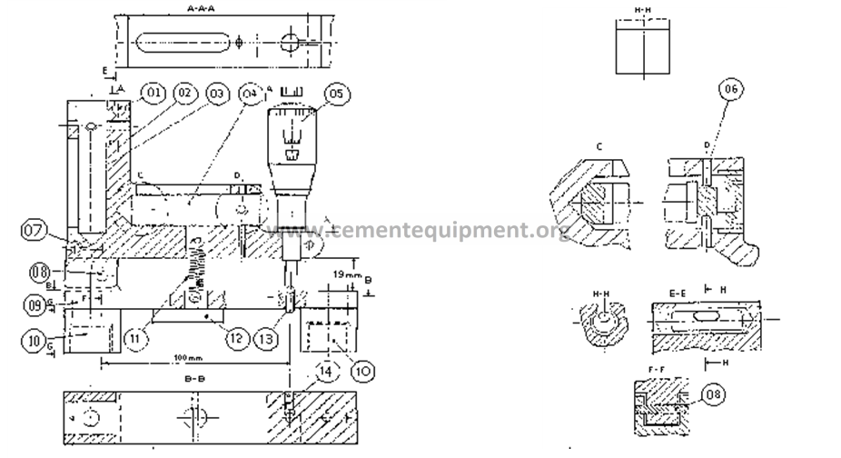
Figure 5.1
The bigger bubble levels (03) and (04) are used to measure deviations of the vertical and horizontal plane inclination, respectively. The bubble levels are mounted in such a way that they can be regulated using the adjustment screws (06).
The small bubble levels (01) and (07) are directional levels used to control the position of the inclinometer in the plane.
When the inclinometer has to be used in rounded surfaces for example, trunnions of rollers, the Magnet Holder can be provided with a support bridge that can be attached to the magnet holder using a milano tail (12).
The distance between the micrometric screw (05) and the spike (08) is exactly 100 mm. Therefore, the millimeter graduation of the micrometric screw will correspond to the inclination percentage, so, 1 mm is equivalent to 1% of inclination.
In the micrometric screw 0.002 mm, its equivalent to an inclination of 0.002%, or 0.02 mm, by 1000 mm
The reach of measurement of the micrometric screw is 0 – 25 mm, nevertheless, the hinge, between the Magnet Holder (09) and the bubble level holder (08), limits the clinometer’s reach of measurement to 0 – 20 mm, that is about + / – 10 mm
5.3.1.1 Control of the adjustment
The inclinometer is provided by the supplier already fixed, however, the adjustment must be controlled before using the inclinometer. The adjustment must be verified always if the device has been used previously.
The adjustment can be considered as correct when the inclinometer is in horizontal plane, the bubble is centered and the micrometric screw is placed in 10.000 mm The adjustment demands a high degree of exactitude and can be difficult if a precise angular plane is missing, for example from a machine tool or a mark end.
When it is only necessary to measure in vertical plane, for example in ends of support sheaves axis definitively mounted, that is our case, it will be more advisable to perform an adjustment in the top screw with sphere (13) until assure that the bubble level (03) is in perpendicular position to the magnets support face, when the micrometric screw is adjusted to 10.000 mm
5.3.2 Frequency
The measurement of the rollers inclination must be made annually.
5.3.3 Procedure, calculation methods and results
5.3.3.1 Measurements of rolls inclination (support sheaves)
The device must be handled carefully. For example, the arm does not have to hit with excessive force the edge, such a blow can modify the adjustment of the inclinometer.
Hold the inclinometer in the inclined plane using magnets (10).
Control with the directional levels to have the inclinometer parallel to the inclination direction. In measurements due in trunnions, the inclinometer must be on vertical position upon the axis line in the same axis.
Turn now the micrometric screw until the bubble of the chosen level is centered. Read the value h in the micrometric screw and calculate the inclination percentage V as following:
V = 10 – h %
The sign depends on the inclination sense and the inclinometer position, nevertheless, the sign has not any meaning considering that the inclination is indicated in percents and the inclination sense has been established.
-Measure in both trunnions. In unloaded support sheaves the measurements must be identical, that is to say that the deviation degree of 10,000 must be the same one if the measurement has been performed correctly. In support sheave under load a difference of a few thousandths of percentage between the two measurements may appear.
Control, at the same time, if the axis ends are perpendicular to the trunnions. This can be important during later measurements that only can be made in the axis ends When measuring the inclination of definitively mounted support sheaves, normally the inclinometer is placed over the turned axis ends of the support sheaves and it is measured, at the exit end of axis as in the entrance end, an average value is then calculated.
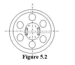
It is necessary to be assured against inaccuracies as a result of irregularities in the mechanized of the axis ends measuring in both sides of the axis center and use the average value of the two measurements. See the figure number. 5.2.
The inclinometer must be placed in such a way that the line in the magnet holder flank (09) is located exactly upon the horizontal line of axis of the same axis, as shown in figure. 5.3.
If the inclination in a support sheave under load is measured, according to the described method, an insignificant divergence between the measurements of both axis ends can be appraised (as previously mentioned), as a consequence of the bent in one of the support sheaves. This is not an anomaly symptom and applying the average measurements when performing the inclination estimate is compensated by this divergence.
5.3.3.2 Operation Procedure.
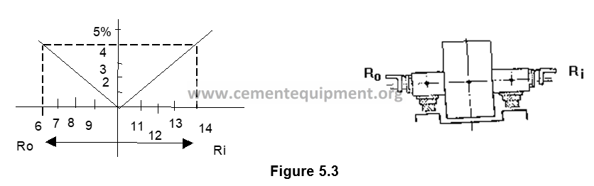
Carefully clean the axis ends before perform the measurements.Measure firstly the superior axis end, next to the entrance of the furnace. Measure both sides of the axis center and compute the average value R i . See figure 5.3. Next, measure next in the end of inferior axis, nearest to the output, and compute the average value R 0 based on the measurements conducted here.
The numerical value of the two measurements will be in the proximities of the value for the horizontal plane, as shown in figure 5.3 and the inclination of the support sheave could consequently be established as:
R i – R o
R m = ———— %
2
Once the two measures R i and R 0 have been taken, it will be necessary to establish their deviation of 10,000, that means the inclination percentage for both axis ends Being an unloaded sheave of support, both percentages must be identical, and in a support sheave under load the reciprocal difference does not have to surpass 0,02%. In case of having a superior divergence it means that the measurements have not been taken correctly and, therefore, will have to be repeated.
5.3.4 Interpretation of results
The difference between the inclination percentage in the entrance and exit extremes of the support sheave must surpass the 0.02%. As well as the maximum deviation of parallelism between support sheaves (rollers) and the tread hoops (rims) must be 0.02%. In all cases the indications of maximum inclinations the mentioned in the position plane corresponding to furnace must be followed.
5.4 REMARKS AND OBSERVATIONS
In some cases the end faces of the rolls cannot be used as a base for the inclination measurement, as in the case of furnaces operating in good condition during a long period. The measurement of the inclination can be performed, doing double measurements in each end of the axis, while the support sheave is turned 90º between the two double measurements.
In the case that this operation does not offer a sufficiently reliable result either, it will be precise to disassemble the superior part of the rowlock, in order to be able to perform a control measurement on the trunnions.
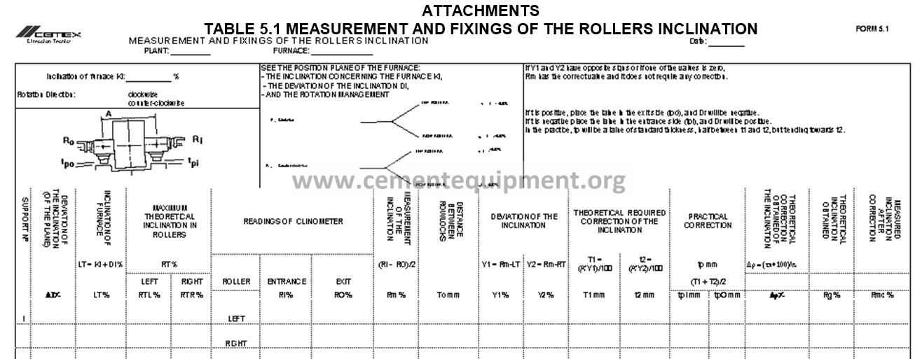
5.5 ANNEXED AND USED FORMS
In Table 5.1 is the form used for measurement and fixings of the rolls inclination of the furnace.
Chapter 6 ROLLERS PARALLELISM AND FLOTATION (Or kiln tires)
6.1 OBJECTIVE AND SCOPE
The objective is to maintain the rollers (or kiln tires) in correct position in order to control the axial pushing exercised by them.
6.2 METHOD BASIS OR FOUNDATION
The kilns by design require an inclination to operate, and for this reason a status must be maintained so that the axial pushing is controlled in order to maintain the kiln free of pressure or floating.
Different types of kiln design exist, which have different needs to maintain the kiln in flotation.
6.2.1. Floating kilns
In these kilns the requirement is fundamental in the adjustment of support rollers by inclinating them, to carry the axial gravitational pushing and by this way maintaining the kiln in a floating position. In this position, the tire (kiln tire) does not have contact with any axial pushing rollers (candlesticks), when the kiln has load and when the temperature conditions are considered as normal as long as the material is being processed. From this floating position, the kiln is displaced upwards or downwards until getting contact with the axial pushing rollers (candlesticks).
6.2.2. Kilns with gravitational or complete axial pushing
These kilns are usually long, heavy, and with antifriction bearings on the axial pushing assemblies (candlesticks), and they are capable to allow axial gravitational loads, with all the kiln support rollers on a neutral position, with the longitudinal shaft parallel to the kiln shaft.
6.2.3. Kilns with axial pushing hydraulically operated
The arrangements where the hydraulically operated axial pushing is utilized, consist essentially in a hydraulic jack positioning the kiln and pushing it upwards when the pump is activated and when the kiln is to be lowered or returned to its position, the pump is stopped. The constant travelling of kiln intends to eliminate the unequal wear of tires (kiln tires), and the gearings teeth in transmission.
6.3 DEVELOPMENT OF THE METHOD
6.3.1 Equipment and tools to be used
– Measuring tape
– Impact wrench to move rollers bearings
– Dial Indicators (watches)
6.3.2 Periodicity
The axial pushing revision must be made every 6 months as minimum, although a daily inspection per shift will provide a clear idea about the need to make adjustments in the rollers inclination in order to prevent overloads in the axial pushing rollers.
6.3.3 Procedure, calculation methods and results
6.3.3.1 Floating kilns
In these kilns the axial pushing rollers must not be forced to perform pushing operation, only check that it does not have overload.
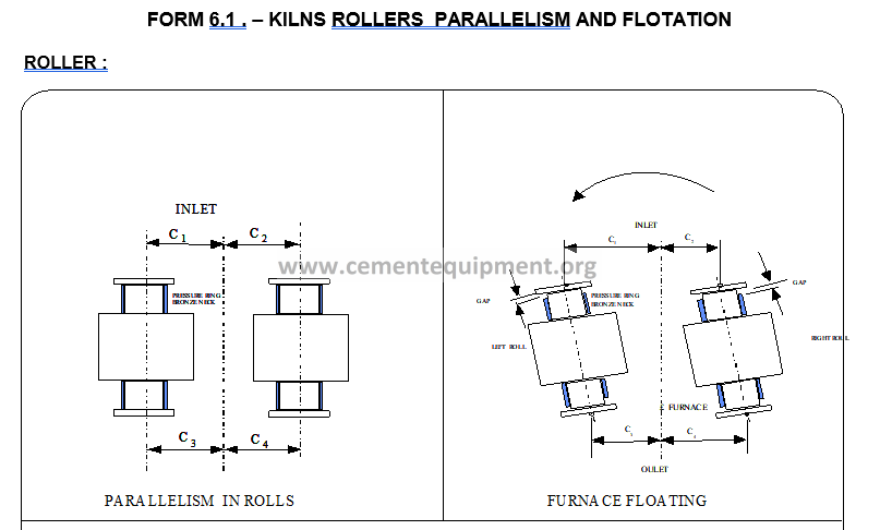
The bearings movement must be monitored by watch (dial) indicators in order to prevent an over adjustment of any assembly, and having all the support rollers with an approximate equal load. See Figure number 6.1
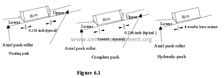
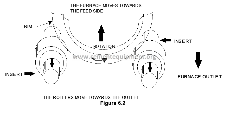
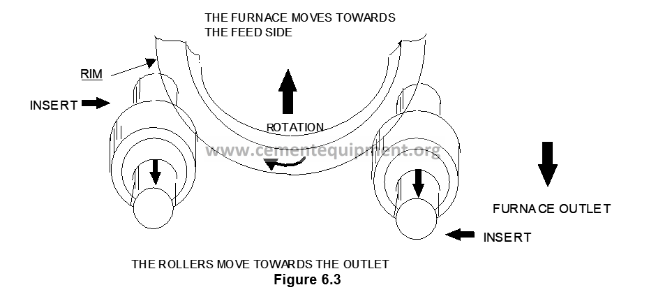
The adjustment begins with a known neutral position, by positioning the rollers longitudinally parallel to the kiln shaft, the rollers start inclination, as required by the kiln rotation direction, to move the tires upwards or downwards, beginning to displace the kiln shell, reacting to the rollers movements. See Figures 6.2 and 6.3. The variances in material quantity inside the kiln, affect the rollers and the kiln axial movement. With rollers inclined for a long period in typical conditions, the heaviest production loads will increase reloads in the axial pushing roller (candlestick) in the direction(s) determined by the inclination angle. Heavy loads cause severe reactions, light loads cause light loads.
6.3.3.2 Kilns with complete gravitational axial pushing
As the axial pushing assemblies are capable to carry gravitational axial loads, it is required that the support rollers are in a neutral position and parallel to the kiln shaft.
In order to make corrections, the best practice is to make small movements regarding the rollers neutral position, by deliberately inclining the rollers to make their pushing plates push downwards. In many cases, this can be done by inclining them 0.125 mm – 0.250 mm in the parallel position correct direction.
6.3.3.3 Kilns with hydraulically operated axial pushing
Due that the movement is made here with the hydraulic system the support rollers must be parallel to the kiln shaft, to make the kiln traveling freely.
To make adjustments, the procedure is equal to the previous case, moving the screws to their neutral position. This can be made by a slight inclination to lighten part of load in the axial pushing hydraulic system to move the kiln to its upper position.
It is extremely important that the inclination adjustments in the support rollers do not cancel totally the kiln gravitational pushing; in this manner it is possible to move the kiln upwards without the help of the hydraulic system.
6.3.4 Interpretation of results
The movements performed must be recorded in the attached forms, and this will serve for future movements, which will strongly depend on the kiln type and its load.
6.3.5 Safety concerns
It is always dangerous to work close to a rotary kiln. Due that measuring and compare the parallelism and flotation of kiln rollers it is required to work very close to the kiln, the appropriate clothing, safety goggles, safety shoes, gloves and safety helmet must be utilized.
6.3.6 Condemning or permissible limits
6.3.6.1 Floating kilns
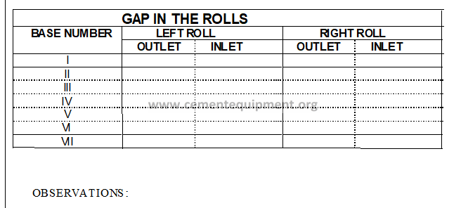
The point to be observed here is to never let the axial pushing rollers be overloaded, it means that the 6 mm separation must exist between the tire or tread ring and the axial pushing rollers.
6.3.6.2 Kilns with gravitational axial pushing
As in the previous case, but with the difference that in the lower axial pushing roller contact must be made with the tire (kiln tire) tread ring, and the separation with the other axial pushing roller, will be maintained in 6 mm.
6.3.6.3 Kilns with hydraulically operated axial pushing
The kiln must normally be allowed to travel a distance between 38 and 50 mm, from the lower position to the upper position.
6.4 COMMENTS AND OBSERVATIONS
The rollers assemblies adjustments require patience, the work must not be done carelessly. Every roller is moved to its neutral position (without inclination or pushing in any direction) and then the adjustment movements must be made from 0.125 mm to 0.250 mm at the same time, followed by a waiting period to let the kiln react, until the moment when the axial pushing conditions are corrected by the supporting rollers, and for kiln arrangement.
A rule of thumb exists to perform the movements, and it consists in the following:
1.- Place a hand as though you were holding (grasping) the roller in favor of its spinning sense.
2.- The index and thumb are extended.
3.- The index finger indicates the bearing pushing, and the thumb indicates the adjustment or movement caused in the kiln.
4.- As the thumb indicates the direction towards the movement will be made, from here can be seen what hand is used, left or right, and corresponding to the left bearing and right bearing respectively (if the roller is seen from the front position).
6.5 ATTACHMENTS AND FORMS USED
The most commonly used forms are the following:
Form 6.1 -Parallelism and flotation of kiln rollers.
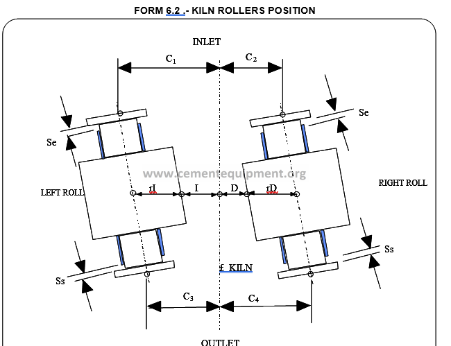
Form 6.2 -Position of kiln rollers.
Chapter 7 CONTROL AND EVALUATION OF ALIGNMENT IN HOT (RUNNING) AND COLD ENVIRONMENT (KILN SHUTDOWN).
7.1 OBJECTIVE AND SCOPE
The objective of the present procedure consists in presenting the most useful methods to perform the kiln alignment control increasing its service life.
With in a well aligned kiln, advantage exists that it will not be submitted during the running operation to hazardous flexion stresses, nor will it gravitate in some kiln tires (tires), a bigger part than the provided in the kiln load, producing disturbances as for example the facets (marks) and punctures (or pitting) formation on the bearing (tires) support faces and the kiln tires. A kiln without correct alignment, will have a force consumption exceeding the normal consumption. Therefore, the kiln must be timely realigned, in order to locate the centers again on a straight line.
7.2 METHOD BASIS OR FOUNDATION
Within the methods utilized for rotary kiln alignment control and evaluation, are the following:
– In running operation or in hot environment alignment.
– In cold environment with the kiln shutdown or out of running.
In both cases the kiln is examined based on vertical and lateral leveling.
After determining the required alignment correction as the case may be, there are factors to be considered: The clearance between kiln tires and the kiln tube, the tube ovality and gearing set from the teeth gearing. These procedures are seen separately.
7.2.1 Alignment in hot environment (running operation)
There are more growing demands regarding the rotary kilns alignment, to prevent shutdowns in the productive cycle, this method has been developed to prove the vertical and horizontal shaft of a rotary kiln, with the kiln running. The immediate advantage of this method consists in the fact that the data collected, over which the kiln status is determined, correspond to its real running conditions. The correction of eventual mistakes can be instantaneous or can be planned, according to convenience for an anticipated kiln shutdown.
In the measuring system development, the technicians have been struggling in complying with this new technique utilization with respect to the following demands:
- The instruments are simple, accessible, transportable and easy to handle.
- The method is assured against erroneous handling of instruments by the operator, through incorporated control devices.
- The expenses originated by the measuring are part of a very competitive order regarding the traditional measuring methods, considering specially that with the new system it is not necessary to interrupt the clinker production.
- The method is based on different data composition in order to determine the kiln definite shaft, which will be commented as follows:
7.2.2 Alignment in cold environment (kiln shutdown)
This method is very similar to the hot environment method, with the difference that a shutdown of 48 hrs. is required as minimum.
7.3 METHOD DEVELOPMENT
7.3.1 Equipment and tools to be used
The essential instruments and devices to develop the corresponding work, are the following:
– Theodolite with 10 sec. Minimum precision.
– Precision level.
– Target graded or rule (level rod) in mm.
– Universal combination square.
– 600 mm. mechanical square
– Metallic metric tape (measuring tape).
– Measuring equipment for rollers diameter (or support rollers).
– Pyrometer for temperature measuring
– Magnetic tips
7.3.2 Periodicity
The kiln shaft alignment verification must be contemplated in the preventive maintenance activities, corresponding to the median repairs, otherwise annually.
In case of any eventuality or doubt in the operation due to excess of current intake in the kiln main motor, overload in rollers, checks must be made to know if the cause is due to kiln misalignment.
7.3.3 Procedure, calculation methods and results
In order to determine the kiln alignment conditions, the kiln position (mounting) drawing must be available, where the support rollers (tire) diameters are indicated, as well as the distance between the kiln base or foundation.
The temperatures of the kiln shell and tires are also involved, which are obtained with a pyrometer, as well as the tires diameters.
7.3.3.1 Alignment in hot environment (running)
7.3.3.1.1 Horizontal alignment.
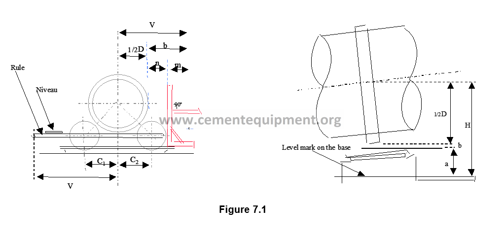
This leveling can be made as long as the kiln is running. Through a leveling instrument, special optic measuring (with level), a height elevation is marked in all the base or foundation.
The above involves taking away the bearings by the lateral parts, in order to place the magnetic tips on the shaft, once they are placed, the level rod or rule is placed, where a level must be placed, to check if it is well leveled.
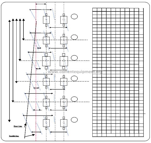
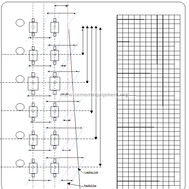
See Figure number 7.1, which illustrates the form to place instruments.
The height elevations form a horizontal plane, from where are determined, through horizontal straight rules, the measures “a” and “b” to be used in determining the height H measures.
Once this data is known and taken as sighting line, both magnetic tips of the same side (entrance and exit) are placed, and a verification of separation between rollers trunnion shafts centers is made.
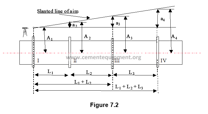
In the position plane appear marked corresponding height measures series, which have likely been calculated from another horizontal plane. Therefore, the differences between the height measures of the different kiln supports shall be the same, as long as the kiln was correctly aligned, while the differences between them directly indicate how much the deviation is of the kiln shaft from the straight line
Examinations also can be made for the height differences H-H1 = “a”. They will be corrected in the same way that is in the oblique sighting (Figure 7.2), and the deviations will be alignment mistakes.
For the determination of the corrected shaft kiln exist the following relations:
a4 = A4 – A1 a3 = a4 (L1 + L2) / L
a2 = a4 L1/L a1 = 0
The correction distances “a” can also be determined by means of drawings.Afterwards the theodolite is placed aside the kiln close to the lower support, and the distance between the optic sighting line and a vertical level rod (or plank) is measured. The “n” measure is directly measured, after this procedure the lateral measures “b” will be determined.
The measures V can also be determined, by measuring the distance between an optic sighting line and the kiln shaft determined with basis on supports positions measuring. If both support rollers have the same diameter, then the result will be it and C2. If little difference exists between both support rollers (or supports) diameters, the calculation can be made approximately just with the condition that the lowest is closer to the kiln shaft than the other as much as the difference between both diameters.
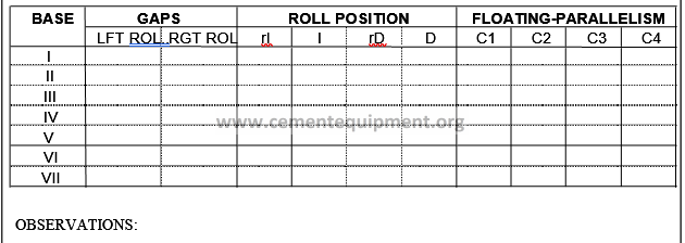
Two forms types (7.1 and 7.2) exist. The format to be utilized, depends on how sighting line was traced, i.e. it depends on the discrepancy of the line traced by theodolite regarding a kiln shaft parallel line.
Once this data is checked, they are transferred to the form 7.1 or 7.2 depending on the place where the sighting line was traced, and by triangles difference a1, a2, etc.. are determined, as previously mentioned.
Knowing this data (from shaft line to sighting line), the kiln normal axis was plotted by taking a kiln ideal axis as reference.
7.3.3.1.2 Vertical Alignment
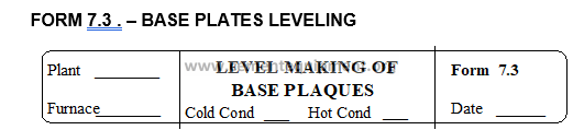
A special optic measuring is made (with level) for level differences between the N number of base or foundation of the kiln, taking as point of reference the kiln tires base metallic plate (or rollers), of support, in the entrance side, (see Figure number 7.1 and form 7.3), although it is most recommended to take also the base plate exit point, in order to average both readings and obtain more real data, as the case may be that the base plate is just unleveled on an end, unfortunately this is not possible for the majority of the cases, due to the place where the appliance is placed does not allow to have an appropriate angle to see and take these two readings.
The recommendation is to place the appliance over a firm place, without any vibration, as well as to protect the appliance from kiln heat radiations to prevent reverberation, with this we can assure to have real data, in order to obtain this, it is necessary to be well coordinated with the person who stops the level rod in the indicated place, which must be two levels, one of them to control the lateral position and the other to control the frontal position. It must be perfectly leveled.
In Figure number 7.1, is illustrated the form in which the appliances must be placed in order to measure, whereas in Form number 7.3, is schematically illustrated the procedure, and are noted down the values checked as well as the drawing data related to how it remained originally (in the mounting operation).
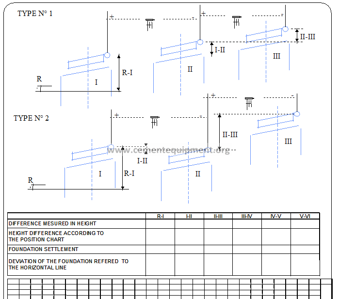
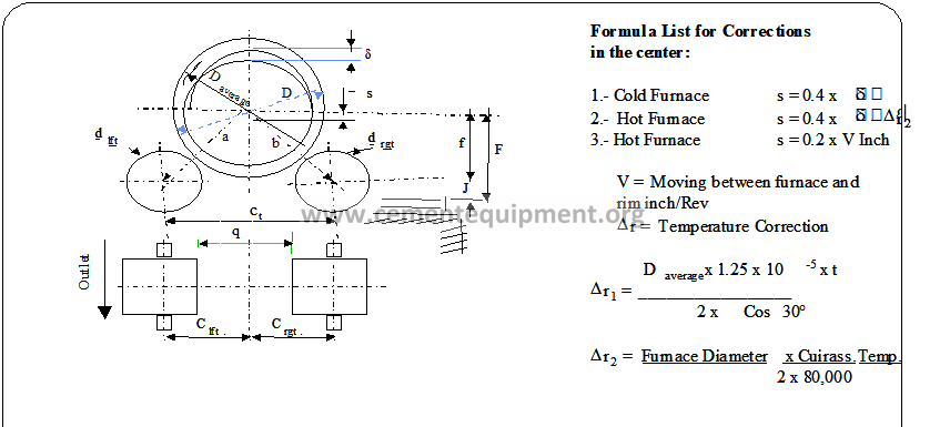
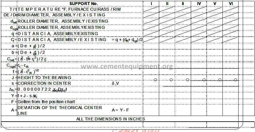
Once the calculations of form 7.3 are made, we will calculate the data required in Form 7.4, where the temperatures are involved, for the kiln shell as well as the tires, which are obtained with a pyrometer, as well as the tires diameters and the displacement, determined through the appropriate procedure, as well as position drawing (mounting operation) data.
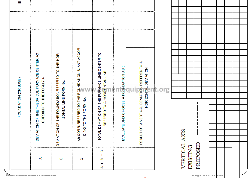
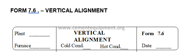
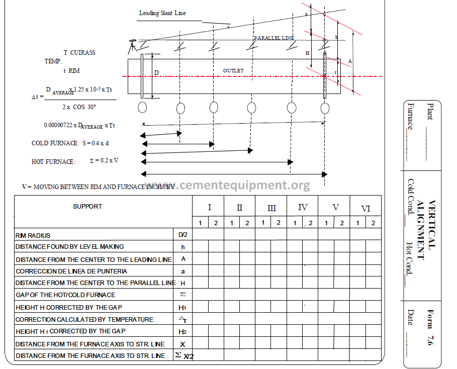
Once the final data (A = Y – F) is determined from Form number 7.4, we transfer the data to Form number 7.5, where the data of the form number 7.3 is also written, in the section of Form number 7.6, that asks us to make a foundation “0”, preferably base III is considered, in order to prevent as much as possible to have movements influencing the axial device as well as in the gear ring, we can finally obtain the values indicating the vertical position of the kiln, and with these values, we proceed to plot it in the lower part of the form. See Form 7.5.
7.3.3.1 Alignment in cold environment (running)
Unlike the method for the hot environment, by means of this procedure if it is necessary to count with a kiln shutdown and a minimum time (48 hours); to get the kiln totally cold this method is almost unused, just as reference, because the data obtained in cold environment conditions, varies considerably from the data obtained under normal running conditions. As in cold environment only a picture of a kiln position is obtained, it is recommendable in doubt cases, to obtain the alignment in cold environment conditions on several positions.
The equipment utilized in this method is very similar to the ones used for the method in hot environment conditions, additionally to the same recommendations that must be followed in order to prevent mistakes.
7.3.3.2.1 Horizontal alignment.
A special optic alignment is made (with theodolite) for this purpose; first mark the tire center and then find the geometrical center related with the kiln shaft. See Figure number 7.1.
The information obtained in this process, is stated in Form number 7.1 and 7.2 (depending on the place where the sighting line is traced), corresponding to the format for horizontal alignment under in cold environment conditions, in this figure, a clear and detailed sight can be obtained, as well as in the method in hot environment conditions, this calculation is also made through similar triangles.
7.3.3.2.2 Vertical alignment.
The special optic measuring (with theodolite), unlike the method in hot environment conditions, in this case the measuring must be made over the kiln, where the level rod is placed to trace the sighting line over the upper part of the tire. Another difference in this method, is that in this case the clearance between the shell and the tire can not be obtained through the gap and displacement metering appliance because the kiln is shut down, and this is one of the necessary values to determine the vertical alignment, this data is obtained by measuring directly the clearance in the upper part of the shell, through shims. Once all the required parameters are obtained, they are transferred to Form number 7.6, and the next step is to calculate the kiln shaft location in vertical position.
7.3.4 Interpretation of results
When the kiln alignment is revised, it is very important to program its correction, if needed, due to the exposed reasons.
7.3.5 Safety aspects
It is always dangerous to work close to a rotary kiln. To measure the kiln alignment it is required to work very close to it; Appropriate clothing, safety goggles, safety shoes, gloves and safety shield must be utilized.
7.3.6 Condemning or permissible limits
The error average in the kiln shaft determination will be maintained in the majority of cases within +/- 1.5 mm., in the horizontal plane and +/- 2.5 mm. in the vertical plane, otherwise the necessary correction must be made.
7.4 COMMENTS AND OBSERVATIONS
This procedure requires the execution of other procedures, therefore the person who performs the control operations, must know the procedures. The related procedures are the following:
H-001 Measuring the gap (clearance) and displacement (clearance control), between the Kiln shell and the tire (bearing tires).
H-003 Measuring the rollers and tires diameters (in cold and hot environment conditions).
H-005 Parallelism and flotation of rollers (or kiln tires).
The alignment correction, is very linked to the previous procedures, thereby its observation must have extreme care to perform any adjustment in the alignment.
When performing corrections, the transmission must be observed in order to make the necessary adjustments.
7.5 ATTACHMENTS AND FORMS USED
The utilized forms are the following:
7.1 Horizontal Alignment
7.2 Horizontal Alignment
7.3 Base Plates Leveling
7.4 Vertical Alignment
7.5 Vertical alignment
7.6 Vertical Alienation
Two format types exist for horizontal alignment, depending on the manner how the sighting line was traced, i.e. the discrepancy of the line traced by theodolite with a line parallel to the kiln shaft.
For vertical alignment, there are three format types and they are utilized in combination.
Chapter 8 CONTROL OF MOVEMENTS (ADJUSTMENTS) TO CORRECT KILN SHAFT.
8.1 OBJECTIVE AND SCOPE
Perform the necessary displacements of support rollers bearings, in the transversal sense in order to correct deviations detected in the kiln alignment revision, through the use of high-pressure jacks.
8.2 METHOD BASIS OR FOUNDATION
The kiln shaft alignment adjustment can be performed during the normal operation, through a special 2000 bar high-pressure jack, if the intention is to move up the kiln shaft, or simply to loose the screws fastening the kiln tires, to make the kiln shaft descend.
The high-pressure jacks are utilized for tire bearings displacement in the connection kiln transversal sense with the position adjustment for the kiln tire or the kiln shaft alignment.
The jacks can be also used when performing a change of kiln tire or a tire bearing.
These high-pressure jacks are mostly utilized in the F.L. Smidth bearings types 58, 74 and 80.
8.3 METHOD DEVELOPMENT
8.3.1 Equipment and tools to be used
The equipment is composed by a manual pump (01) with an oil tank, 2 high pressure cylinders (02) (high pressure jacks), a high pressure manometer (07), a distribution piece (11), and also three high pressure hoses (06), and three quick couplings (03) and (04). See Figure number 8.1.
The equipment also includes an angular meter (15). See Figure number 8.2.
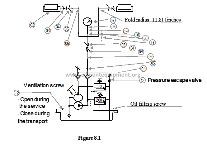
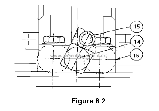
Both cylinders are interconnected and are placed on each side of the adjustment screw (14), of tire bearing, between the bearing base and the fastening piece (16). See Figure number 8.2.
The cylinders are connected to the distribution piece and the manual pump through the hoses.
The adjustment screw (14) is the component, which determines the tire bearing position in the kiln transversal sense, so that, a bearing position modification, is performed when spinning the adjustment screw. As a consequence of the enormous load coming from the kiln tire, the kiln tube, the coating and filling operation, the bearings are pressed towards their adjustment screws, with so much force, that they can hardly spin. See Figure number 8.3.
Both jacks help to relieve the pressure acting over the adjustment screws, whenever a spin on the screws is wanted.
8.3.2 Periodicity
This procedure is utilized provided that the kiln shaft position correction is desired as result of its alignment review.
8.3.3 Procedure, calculation methods and results
8.3.3.1 Mounting and operation
When placing the equipment (see Figure 8.3) attention must be paid that the high-pressure hoses can only bent with a radius not lower than 300 mm.
The trajectory of piston, high-pressure jacks, is 10 mm., for this reason it can be necessary to place supplements (shims or wedges) between the jacks and the fastening piece (or tightening).
It is very important that the faces, where the jack’s pressure is exercised, are completely parallel, as otherwise the jacks could be damaged.
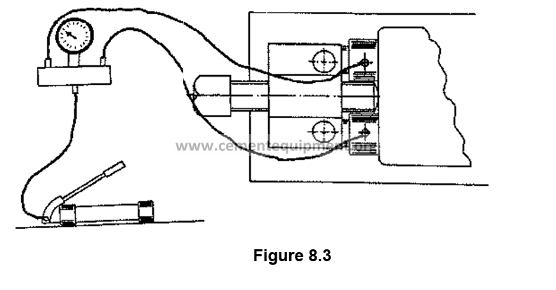 Before starting the operation must be determined, how much and in what sense must the corresponding bearing be displaced and calculating, according to that, the equivalent spin to apply to the adjustment screw.
Utilize the following formula:
L X 360
G = ————
S
Where G is the number of degrees to spin the adjustment screw, L is the wanted distance to displace the bearing measured in millimeters, and S is the screw thread passage, also measured in millimeters.
For example if the desire is, to displace a bearing 0.2 mm towards the kiln theoretical shaft and the adjustment screw thread passage is 4 mm., the screw must be spinned:
0,2 X 360
—————- = 18° to the right
4
This operation is performed in the following manner:
- a) Loosen the supporting bearing fastening pins.
- b) Open the manual pump ventilation screw (12), (see Figure number 8.1) and start pumping, at the same that the manometer pressure is maintained under continuous observation.
In Table number 8.1 is specified the maximum admissible pressures for distinct bearing sizes. These colors must not be exceeded as this condition can cause rupture in the fastening piece fixation screws.
On small frequent cases, where the admissible pressure is not sufficient to lighten the adjustment screw so that it can be spun, will it be necessary to fasten with welding application the reinforcement irons to the seat plate placed behind the fastening piece. In these cases a 10 – 20 % pressure increase can be accepted.
- c) As soon as the adjustment screw can be spun, place the angular meter over the screw head, by spinning the screw as many degrees as necessary in the correct direction.
- d) Open the manual pump unload valve (13) The bearing will quickly slide outwards until the moment when it has contact again with the adjustment screw.
- e) Tighten again the bearing fastening screws.
It is important that the operation must be realized as quickly as possible in order to prevent bearing heating condition. The adjustment result must be controlled with axial measuring equipment, as mentioned in the pertinent directions.
The supporting bearing movement, during the operation, can be eventually controlled through a micrometer with quadrant placed in the bearing base.
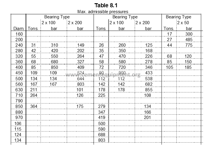
8.3.4 Interpretation of results
After every roller movement or adjustment wait for some time to let the kiln stabilize itself in order to observe its behavior, by doing this the kiln shaft will move to its correct position.
8.3.5 Safety aspects
Care must be given to observe that the hoses are absolutely intact, as the usage of defective hoses implies serious risk to personal damages.
It is very dangerous to work close to a rotary kiln. As when performing the lead trials it is required to work very close to it, appropriate clothing, safety goggles, safety shoes, gloves and safety shield must be utilized.
8.3.6 Condemning or permissible limits
Whenever the rollers movement is executed the following must be observed:
– The support rollers cut must not be higher than 2 mm.
– Cutting operation for support rollers with pine shape are not allowed.
– The cutting operations must be executed in one or two rollers group at a time.
Whenever the support roller diameters difference is 20 mm or higher, its surface must be rectified.
8.4 COMMENTS AND OBSERVATIONS
The rollers movement must be made carefully, as otherwise kiln uncontrolled critical situations will arise.
Chapter 9 CONTROL OF CONTACT BETWEEN ROLLERS (support rollers) AND TIRES (kiln tires), THROUGH LEAD WIRE
9.1 OBJECTIVE AND SCOPE
Confirm and control the kiln supports positions during the kiln running or normal operation, through trials with wire lead.
9.2 METHOD BASIS OR FOUNDATION
9.2.1 Principle
The method is based on analyzing the crushed lead wire form, after introducing it between the kiln tire and the support roller, which will provide the following information:
- The surface pressure between the kiln tire and the support roller
- The inclined position of support screws (rollers) regarding the kiln shaft (its intersection).
- The support rollers position in the lateral sense.
- The relative load on every support.
- The kiln tube warping, if existing.
9.2.2 Method utility
The trial through lead wire can be utilized in the mounting operation to confirm the kiln tires inclination, but its primary objective is the kiln supports positions control during the normal running operations.
The compressed wire form will serve as illustration for the pressure conditions existing between the kiln tire and the support roller along the surface where the crushing will take place.
A trial isolated with lead wire is extremely difficult to be evaluated as are there are many factors contributing to provide the lead wire with its crushed form, as mentioned subsequently.
The trial results are easier to be evaluated when intending to perform a comparison between two trials, for example, performed before and after a supports position correction. The difference between these both trials will provide an authentic image of the correction effects.
Also, trials performed systematically and methodically when compared against other periodic measuring, will clearly show eventual modifications in the kiln alignment.
The trial with wire lead alone must only be considered as a relatively simple remedy for the kiln mechanical preventive maintenance, and there are series of factors influencing the result, for example:
The very hot kiln roller (tires), can cause higher crushing than the own pressure.
The supporting faces poured (cast) and deformed in the kiln tires and the support rollers will give a false image of the pressure conditions.
The wire leads quality and diameter.
The running conditions of the same kiln, i.e. rings formations, load distribution, formation of crusts and other adhesions, refractory status and nature, special internal installations to improve the kiln economy, etc..
9.3 METHOD DEVELOPMENT
9.3.1 Equipment and tools to be used
– Vernier or thickness gauge
Additionally a wire lead with 2 – 3 mm diameter is required. Cut the wire lead in pieces of a length equivalent to the kiln tire width. 20 – 30 cm bigger makes it easier to fasten it.
9.3.2 Periodicity
Under normal conditions it will be sufficient to perform the trial with wire lead every 3 months period.
Nevertheless, during the first period of a new kiln running, the recommendation is to perform trials with shorter intervals in order to discover timely eventual settlements of kiln foundations or bases.
As a wire lead trial also discloses, if the kiln tube is warped, it must be always made jointly with a normal alignment of the kiln supports and, depending upon the case, consideration must be made for the kiln tube straightening.
9.3.3 Procedure, calculation method and results
The method to follow for the trial with wire lead is to introduce, as long as the kiln is in service, a wire lead of 2 – 3 mm, between the supporting roller and the kiln tire, therefore the wire is compressed, as illustrated in Figure number 9.1.
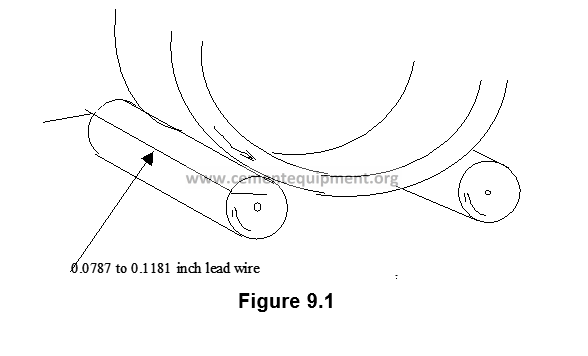
9.3.3.1 Practical method execution
Immediately after starting and the first set in service for a new or just aligned kiln, i.e as long as the alignment is correct, it is recommendable to perform a trials set for all the supports with wire lead.
These trials set will form the comparison basis for all the subsequent trials.
A complete set encompasses six crushed wires coming from each support, three of them for each kiln tire. The trial with these three wires is made in front to three generatrixes, marked in the kiln tube with a space of 120 degrees between each of the, such as illustrated in the Figure number 9.2.
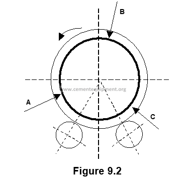
When the three generatrixes are marked in the kiln tube, it is more convenient to leave the generatrix A in the diametral plane, crossing through the man entrances center, and the other generatrixes displaced at a distance of 120° from there. Observe the letters sequence regarding the rotation sense.
Introduce the wire lead between the support roller and the kiln tire just in the moment when one of the generatrixes crosses through the kiln tire.
Provide, carefully, the crushed wire with date, support number, specify if it is right or left tire (seen from the kiln operator) and also write the corresponding generatrix number.

Place the tag on those wire lead end closest to the kiln exit end, see Figure number 9.3.
The result of wire lead trials can be preserved fixing it with adhesive tape to a carton piece, or simply limiting to transfer, carefully, the wire leads contour to a paper and maintain it as illustrated in Figure number 9.4.
With support on Figure 9.4, which we section in 10 equal parts, to be identified as variables t, from t1 to t5, which is the exit side and we identify them as tU and from t6 to t10, which is the entrance side identified as tJ, see Figure number 9.5, the only recommendation is that the marking must be correct.
Subsequently, with the obtained measures the results are introduced in Form 9.1.
The mean values for every wire lead half are calculated, and the result is written in Form 9.1.
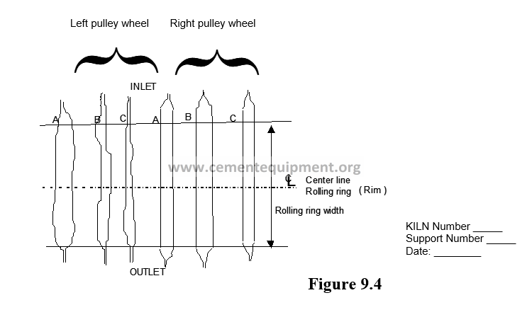
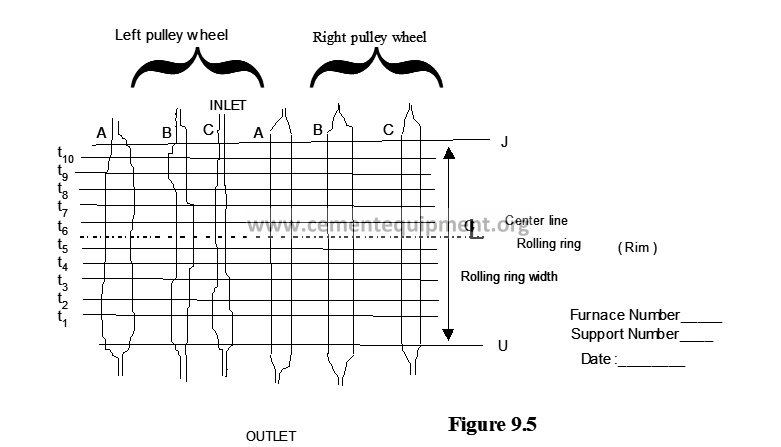
Immediately proceed to calculate the values tu – tj for each generatrix and its mean term is calculated, which is the value utilized to make comparisons.
The mean term results of tu and tj are written on the upper part and in the lower left table, the next step is to make the addition and the average is again obtained for every tire (right and left), subsequently the tire difference is calculated and the average tL is obtained.
The value of tL found, is compared with the value tL of the supports rest, specially with the mean terms previously confirmed for the corresponding support.
9.3.4 Interpretation of results
9.3.4.1 Supporting washers intersection
The kiln tire intersection i.e. how correct is the kiln tire and the support roller orientation regarding the kiln spinning or rotation.
In order to make comparisons the mean term tu-tj is used, if the kiln shaft is rectilinear (without warping), and the different supporting faces are in good conditions, the three differences tu-tj , one for each generatrix result almost equal.
Both kiln tire for a same support must be always of opposed intersection, when the kiln tires are located at parallel positions.
As rule can be specified, that the intersection must not exceed the following values:
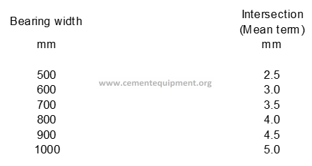
A too big intersection results in a very big surface pressure, in a material overload, and the wanted effect to retain the kiln in the axial sense through an uniform axial pressure of the kiln tire is not obtained.
9.3.4.2 Kiln tire position in the lateral sense
The mean values calculated in the upper part of Form 9.1 are transferred to the lower left part, and the mean crushed widths tH and tV are calculated.
The values tH and tV specify he mean surface pressure, the values are compared, and if the difference exceeds 10%, the tires must be adjusted in the lateral sense. Nevertheless, in the support close to the gearing set a 20 % difference can be admitted.
9.3.4.3 Load over individual supports
Finally the mean width tL of all the wire leads crushed by the kiln tire are calculated. The value tL represents an expression of the kiln tire total pressure over the corresponding support.
The value tL found is compared against the value tL of the supports rest, specially with the mean terms previously confirmed for the corresponding support.
9.3.4.4 Kiln tire inclination
If the lead wire trials insinuate that the tire or roller intersection is normal, whereas an examination on the tire supports show that the tire presses the roller downwards, the cause will be that the tire support face is not parallel to the kiln shaft. The tire or roller inclination must be corrected, through wedges (or shims) under one of the supports.
Additionally with the lead wires trial detection of irregularities as the following can be made:
9.3.4.5 Kiln tube warped
If the kiln tube (or shell) is curved, the pressure will vary between a kiln tire (tire) and the corresponding rollers during the kiln rotation, generating different crushing on every generatrix.
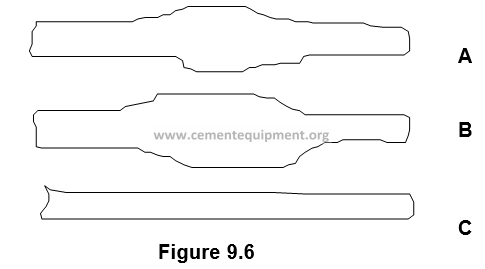
If the kiln shaft is warped, an idea about the warping sense can be generated, by drawing the following diagram:
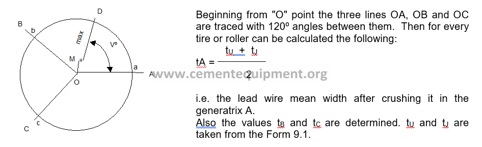
Now in the diagram are traced (for example in scale of 2 : 1), the values tA = Oa, tB = Ob and tC = Oc. A circle is traced by crossing the points a, b and c with its center in M. From Pole O a line is traced crossing M, cutting the circle in D.
A wire trial of lead wire performed in the generatrix D kiln, located at Vº from generatrix A in direction towards B, will mark the maximum crushing, i.e. equal to OD distance, measured in the diagram.
If the major mean width tD, divided by the minor one, generates as result a major value of 1.3 , then the kiln tube must be straightened.
If the lead wires crushing in a tire is higher in one roller than in another one, the reason is because the rollers have been laterally displaced. The pressure coming from the sprocket and the kiln load can generate an unequal crushing and therefore, the rollers position in the lateral sense must not be corrected until the moment when confirming, through a control optic leveling, the kiln shaft.
The maximum surface pressure between the washer and the kiln tire can result as big as with risk of “pitting” or “punctures” generation, if the kiln tube is not straightened.
9.3.4.6 Tires laterally displaced
If the wire lead crushing in a support is higher in one tire than on another, is because the tires have been laterally displaced. The pressure coming from the sprocket and the kiln load can have by effect an unequal crushing and therefore, the rollers (or tires) position in the lateral sense must not be corrected until the moment when, through a control optic leveling, the kiln shaft is verified.
The mean values tH and tV are divided, the highest by the lowest, and in this surfaces pressures ratio the following values can be expected:
In the support where the transmission is: 1.05 – 1.2
In the other supports: 1.0 – 1.1
If a higher ratio is checked, a support control leveling must be verified (i.e. the kiln alignment) and make a correction.
9.3.4.7 Kiln tire (tire) displaced in the vertical sense
If the mean width tL in one of the supports differ essentially from the others, correction must be made in the distance between both tires of each set, i.e. correct the kiln tire position height.
9.3.5 Safety aspects
It is always dangerous to work close to a rotary kiln. As when performing the lead wire trials it is required to work close to it, appropriate clothing, safety goggles, safety shoes, gloves and safety shield must be utilized.
9.3.6 Condemning or permissible limits
The differences in the crushing width, it means the values tu-tj or tj-tu, respectively, depend, among other factors, upon the kiln tire width, and 5 % of it must not be exceeded.
The kiln tube warping provides the mean width variance of the lead wires crushed of a same tire. If the mean width vary more than 30 %, the warping character and extension must be examined differently, considering a kiln tube straightening. If the mean width of all the lead wires crushed of a washer exceed more than 10 % then the mean width of all the lead wires of the other tire corresponding to the same support (but 20 % in the gearings set), the kiln must be submitted to a control leveling.
9.4 COMMENTS AND OBSERVATIONS
The wire trial can be realized quickly and efficiently, but its results are not as exact as to exempt the kiln alignment checking through a leveling instrument.
But the trial by itself evidences, if the optic control is immediately required:
It is not possible to determine in advance an admissible variance of the mean superficial pressure from one support to another, but it is valid as a general rule that if the mean surface pressure of a support apparently is extraordinarily big – or small – regarding the superficial pressures on the other supports, the kiln must be submitted to a control leveling operation.
9.5 ATTACHMENTS AND FORMS UTILIZED
Form 9.1 Alignment through lead wire trials
Chapter 10 CONTROL OF GEARING BETWEEN GEAR RING AND PINION IN KILN THROUGH LEADEN HEELS
10.1 OBJECTIVE AND SCOPE
The main objective of this procedure is to maintain a good contact between the gearings teeth (pinion / gear ring), in order to increase the transmission service life.
10.2METHOD BASIS OR FOUNDATION
The transmission objective is to transmit the motor spinning momentum from the kiln reducer to the kiln tube.
One or two pinions and a sprocket, composed by two or four parts, compose the transmission. The sprocket is subject to the kiln tube through the sprocket springs.
10.2.1 Activating gear ring and pinion wear
The problems occurring with kiln pinions and gear rings are generally originated by:
– Axial warping of sprocket.
– Radial warping of sprocket.
– Lubrication.
The faults previously mentioned, are normally consequences of a permanent or thermal deformation in the kiln tube, causing an overload of gear ring teeth generating as result the contact (support) reduction in teeth width as well as in teeth height.
10.2.2 Gearing failures cause
The gearing failures cause is mainly due to wear on the support rollers, kiln tires, supports, etc., which can mean a reduction of distance between centers between sprocket and pinion, with the effect that the distance between the tooth top and the tooth bottom is too small, i.e. lower than 6 – 12 mm, according to the kiln size.
10.3 METHOD DEVELOPMENT
10.3.1 Equipment and tools to be use
– Leaden heels (24 pieces), according to Fig. 10.1
– Thickness gauge (Vernier)
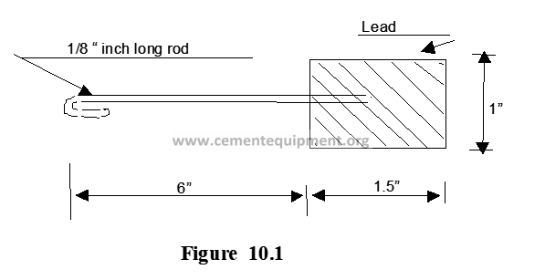
10.3.2 Periodicity
The recommendation is to perform this measuring once a year, or every time the kiln alignment is made.
10.3.3 Procedure, calculation methods and results
First of all the screws set tightening must be reviewed, and in order to control the teeth gearing, the clearance between the tooth top and the tooth bottom must be the same on both sides (entrance and exit).
In order to monitor the clearance between pinion and gear ring, the lateral caps above the pinion must be removed. In case of having two pinions, this measuring operation must be repeated for the other pinion.
The gear rings springs, or their fastening pins, are marked with the consecutive numbers from 1 to 12.
24 leaden heels are manufactured, according to Figure number 10.1.
The leaden heels are marked in 2 sets, with the numbers from 1 to 12; a set corresponds to the entrance side and the other corresponds to the exit side.
The heels are inserted at the pinion back, crossing through the gear ring every time a pin fastens the supports to the gear ring. During this operation, the kiln in hot and / or cold environment, must be spun with the slow spin.
The heels are measured and the measures are recorded in a scheme (polar diagram), see Form number 10.1
10.3.4 Interpretation of results
The gearing teeth must be absolutely examined, before determining the kiln definite alignment. It can be confirmed that what follows is what there is in the mounting between the teeth top and teeth base:
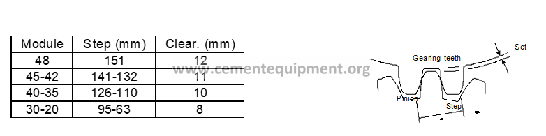
If the confirmed set is not in accordance with these values, an adjustment must be made, duly considering the teeth wear, with arrangement to the clearance indicated above, i.e. that it must be considered when the new kiln shaft is determined. Given the case an incorrect gearing can be corrected by displacing the pinion through command supports intermediate sheets (or shims) thickness modification.
If the contact between the teeth is not correct, this means that the teeth are not in uniform contact along the entire surface, one of the pinion supports could be displaced in horizontal sense. The original position of the support is indicated by chisel strikes in the support basement, and in the seat plate. The supports position can be adjusted through the adjustment screws.
10.3.5 Safety aspects
it is always dangerous to work close to a rotary kiln. Due that measuring and compare the parallelism and flotation of kiln rollers it is required to work very close to the kiln, the appropriate clothing, safety goggles, safety shoes, gloves and safety helmet must be utilized.
10.3.6 Condemning or permissible limits
The maximum permissible clearance available must be 12 mm, and 6 mm as minimum, and in the teeth parallelism confirmation case, the maximum deviation will be 0.01 mm.
10.4 COMMENTS AND OBSERVATIONS
The kiln transmission gearing control is basic for its durability, although it is very important to develop this control when the kiln is steady, i.e. that there is not existing material accumulated in zones.
10.5 ATTACHMENTS AND FORMS UTILIZED
-Form 10.1, Gearing control between pinion and gear ring.
Chapter 11 ALIGNMENT OF THE MAIN TRANSMISSION, GEAR RING AND PINION
11.1 OBJECTIVE AND REACH
The main objective of this procedure is to maintain the transmission aligned, in order to have a good contact between the gearing teeth, to have a more silent transmission and increase the transmission running life.
11.2 METHOD BASIS OR FOUNDATION
The transmission objective is to transmit the motor spinning momentum from the kiln reducer to the kiln tube.
A pinion and a sprocket, in two or four parts, compose the transmission. The sprocket is fastened to the kiln tube through the sprocket springs.
The problems occurring with the pinions and gear rings of the kiln are generally originated by the following:
– Sprocket axial warping.
– Sprocket radial warping.
– Lubrication.
The faults previously mentioned, are normally due to a permanent or thermal deviation in the kiln tube, causing an overload of the gear rings teeth as a consequence of the support reduction in the teeth width and teeth height.
11.3 METHOD DEVELOPMENT
11.3.1 Equipment and tools to be used
– Three stopwatches, two for axial measuring and one for radial measuring, with the necessary brackets, magnetic bases, vises, etc.
11.3.2 Periodicity
The recommendation is to perform this measuring operation once a year, or every time the kiln alignment is performed.
11.3.3 Procedure, calculation methods and results
In the sprocket, 12 visible marks must be painted in the kiln shell, at a distance of 30° between each of them. Number the marks from 1 to 12. The position 1 must be located at level with the inspection or man entrance holes, for future references.
During these measuring operations the kiln must be spin, as much as possible through the transmission, as this provides the safest results.
Three people perform the measuring operations at the same time, in a same kiln revolution.
Continue the slow spinning during a whole additional revolution, and control that the measuring operations results provide the same deviations level.
11.3.1 Radial eccentricity measuring.
For radial eccentricity measuring a stopwatch or depth measuring device is utilized, as illustrated in the Figure 11.1. During both methods of execution it is important that the measuring operation is performed from a persistent bracket, firmly fastened to the base plate, in order to prevent vibration-reading mistakes. First is measured the distance to the turned measuring face of the sprocket.
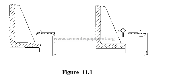
Spin the kiln tube one turn and read the stopwatch / depth meter in front of every mark in the kiln shell. Write the values, by utilizing Form 11.1.
Trace a polar diagram based on the measuring operations. The radial eccentricity sense and size will be detached from the diagram; this will also show if the big deviations are caused by ovality or eccentricity.
When adjusting the sprocket a distortion by tightening it must not be provoked. I.e., when tightening one side the other side must be equally loosened.
11.3.2 Axial warping (run out) measuring
The axial warping can be measured during the same spin of the sprocket.
Two stopwatches must be utilized for the axial warping measuring operation. They are placed on each kiln side, displaced 180° one from each other, but on the same side of the sprocket (both stopwatches will be placed in the entrance or exit side). See Figure 11.2.
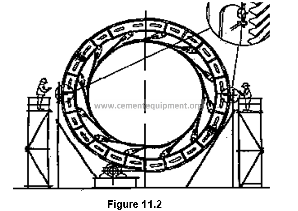
Both brackets, where the stopwatches are placed, must have good stability, in order to have a good measuring result. Both persons necessary to read the stopwatches must be standing up in a bracket or platform, independently from the bracket where the stopwatches will be located, so that the persons movements do not influence the measuring operations.
The reason why two stopwatches are utilize, is in order to compensate for failures generated as consequence likely to the kiln tube axial misalignment, during the slow spinning. Which can be better appreciated by seeing the Figure 11.3.
The Figure 11.3 shows that the sprocket counts with a total eccentricity W, meaning that if the kiln is spun 180°, “A” will generate a positive deviation (+W) and “B” a negative deviation (-W), i.e. if the kiln has not been displaced in axial sense during the slow spinning.
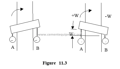
Now suppose that the kiln, during a slow 180° spinning has been displaced (F) mm in the sense indicated by the arrow in Figure 11.4.
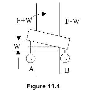
The stopwatch A indicates F+W and the stopwatch B indicates F-W.
In order to find the W value, the value we are interested in, the following method is utilized:
The deviation of stopwatch B (F-W) indicates a negative symbol, it means -(F-W) = -F+W and it is added to the deviation (F+W) in the stopwatch A.
Indication in stopwatch B: -F+W
Indication in stopwatch A: +F+W
Adding 2W
W is obtained by dividing by two.
The method is also valid when the kiln is spun any number of degrees instead of 180°, and as it is compensated mathematically by the axial displacement; the displacement “sense” does not have any sense.
If the sprocket is flat, the curve will always have a sinusoidal form.
In the Form 11.2, the measuring operations results are written. The axial warping must not exceed +/- 0.75 mm.; despite in recent dates (new kilns) a higher demand exists (to increase even more the transmission life), as this value must not be higher than +/- 0.5 mm.
11.3.4 Interpretation of results
The gearing teeth must be absolutely examined, before determining the definite kiln alignment.
Whenever it is necessary to align the gear ring, this must be made immediately, and the gearing of gear ring with pinion must be revised by following Procedure H-010.
11.3.5 Safety aspects
It is always dangerous to work close to a rotary kiln. To measure and control the parallelism and flotation of kilns it is required to work very close to it; appropriate clothing, safety goggles, safety shoes, gloves and safety shield must be utilized.
11.3.6 Condemning or permissible limits
The radial eccentricity must not exceed +/- 1.50 mm, which is the mounting tolerance.
The axial warping (run out) must not exceed +/- 0.75 mm.; despite in recent dates a higher demand exists, as this value must not be higher than +/- 0.5 mm.
In case of exceeding the previous values, a correction must be immediately made.
11.4 COMMENTS AND OBSERVATIONS
The kiln transmission alignment revision is basic for its good running operation, and in order to assure the measuring operations are correct, special care must be given to fix correctly (and never move them during the measuring operation) the dial watches or stopwatches, to prevent erroneous readings.
11.5 ATTACHMENTS AND FORMS UTILIZED
Form 11.1 Radial eccentricity calculation.
Form 11.2 Sprocket axial warping calculation.
Chapter 12 KILN SECTIONS (KILN SHELL) REPLACEMENT, IN WHICH DISTORTION CAUSES PROBLEMS.
12.1 OBJECTIVE AND SCOPE
This procedure, intends to cover whatever is needed when a kiln tube section or kiln shell must be replaced.
12.2 METHOD BASIS OR FOUNDATION
When the kiln tube section or kiln shell must be replaced, this is due first of all to the need of having a good surface for the refractory brick correct placement.
The fault shown by the kiln section or kiln shell requiring its replacement, is normally due to a permanent or thermal deformation in the kiln tube, causing additionally damages in the bricks as mentioned, showing irregular overloads in the support rollers.
12.3 METHOD DEVELOPMENT
12.3.1 Equipment and tools to be used
12.3. 1.1 Equipment and tools
– Portable oxyacetylene cutter, with all its implements, such as rails or guides, blowtorch or gun, etc.
– Welding equipment, with its fittings.
– Alignment sevens or irons or jacks or pins (see Figure 12.1)
– Mounting angles or angular consoles with their adjustment screws (see Figure 12.1)
– Micrometer, with its magnet carrier.
– Punch.
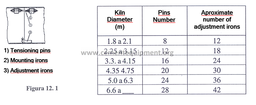
12.3.1.2. Support equipment
– Ultrasound equipment.
– Support beams, to support the kiln shell, they could be railroad mudsills, etc.
– Crane to perform maneuvering, capable to support the kiln shells.
12.3.1.3 Work materials
– Welding application
12.3.1.4.Supporting materials
– Kiln position plan or drawing
– Plan or drawing of disposition, holes for internal installations, etc.
12.3.2 Periodicity
The eventuality in the kiln shells or kiln sections replacement, is made whenever so required, due to problems caused by it when being distorted or deformed.
12.3.3 Procedure, calculation methods and results
First the kiln shell or kiln section size or kiln tube section size are determined, manufactured, the damaged kiln shell is removed, and the new one is placed. Now, next are described in more detail the measuring and kiln shell replacement activities.
12.3.3.1 Determination of damaged kiln tube section measure
1.- The kiln shell diameter and length are determined, with special care that this measuring is made when the kiln is in cold environment conditions, and with these dimensions, and supported by the kiln drawing, a kiln shell can be manufactured in accordance to reality. Caution must be observed in the consideration of rivets, pumped welding applications, splice plates, etc.
2.- With the kiln shell or kiln section dimensions, the new kiln shell can be ordered to Manufacturing.
12.3.3.2 New kiln shell manufacturing and handling
The kiln shell is ordered for manufacturing according to the material and thickness specifications indicated in the manufacturer drawing. ‘
It must be inspected when being received, by measuring the diameter at the ends through a rule assuring it is perfectly circular, and provided with a reinforcement cross, in order to prevent its damage during the transportation and handling. If the kiln shell is thick (higher than 2.85 m.), it must have an extra cross placed in the middle point.
It is recommended to leave the reinforcement cross on its place in the kiln shell, until the moment when it is joined by angles and pins (or alignment pins) with the adjacent kiln shell. As soon as the pins (or jacks) for kiln shells union, and once the joint is centered through the adjustment irons, the reinforcement crosses can be cut, or can be left until after the first bottom cord¡.
If the circular form of the new kiln shell has been deformed previous to the mounting operation, the shoring crosses joists are cut before proceeding to the kiln shells union. Jacks or tensioning pins must be utilized to make the kiln shell return to its circular form. If this work is made during the mounting operation, exclusively tensioning pins are utilized.
The shoring crosses situated in the middle point of a thick kiln shell, must not be removed until finishing its total mounting and welding operations.
When the kiln shell is to be utilized, the chamfers provided for the welding joints must be perfectly clean. All the paint, when burned produces gases and reduces the welding application quality must be removed.
12.3.3.2 Preparation steps
Previous to proceed with the kiln shell removal, and the new kiln shell placement, it is necessary to examine:
- a) The possibilities to transport the pieces, before and during the kiln shell removal, and the new kiln shell mounting.
- b) The elevation devices available, such as cranes, hydraulic jacks, etc.
- c) The possibilities to spin the kiln during the alignment and welding operations. It is recommended to perform spins with the slow spinning device, and in case of utilizing tackles or hoisting machines, observe that the traction is upwards in order to reduce the supports friction.
12.3.3.3 Damaged kiln shell removal, and surfaces preparation
1.- In a convenient extension around the repair place the material, the refractory and the internal installations are removed.
2.- Spinning the kiln, supporting against just one of the guide roller (or candlestick), lines are traced on the kiln shell corresponding exactly to the new kiln length. 100 mm away from each side of these lines, two reference lines are traced, see Figure 12.2. The reference lines are provided with punch marks. Identify at the same time, if a kiln shell warping correction is needed.
3.- The kiln tube is supported as illustrated in the beginning in Figure 12.2, and the kiln shell is cut with the automatic oxyacetylene cutting equipment, and the kiln shell is dismounted.
4.- The kiln tube cut edges are chamfered such as indicated in Figure 12.3.
5.- In case the kiln shell being changed, contains a kiln tire (or tire), this is the time to perform its change, from the old or damaged kiln shell to the new one.
12.3.3.3 New kiln shell mounting
1.- The new kiln shell is placed in its site, and besides the cut in the kiln tube nearest to the entrance, mounting angles are welded, as many as depending on the kiln shell diameter and length.
Normally the adjustment irons are welded in the kiln shells internal wall, with limitation to the number of irons absolutely necessary, see Figure 12.1.
2.- The kiln shell is aligned regarding the kiln lower part (the part towards exit), considering the eventual warping mentioned in Paragraph 2 of the previous point 12.3.3.2. According to the indicated in Figure 12.4, the measure includes the reference line traced, and is internally confirmed through a rectilinear rule.
3.- Internally and externally in the bottom (or lower part) and above (or upper part) of the kiln shell, respectively, a welding cord of 800 – 1 000 length is welded. Internally the complete joint is welded and externally a cord with the same dimensions must be applied, so that, both cords have the same section, in attention to a uniform contraction.
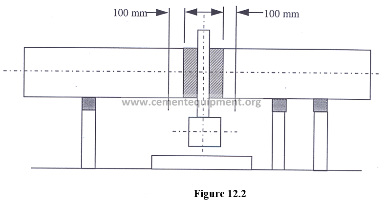
4.- The kiln spins carefully approximately 800-1000 mm, and it is again supported, then a new welding cord with appropriate length can be applied.
5.- Once the joint half is externally and internally finished, the kiln shell alignment must be controlled. In case the alignment is incorrect, it must be corrected by cutting, beveling and welding part of the circular joint welded. If in the previous work the reference line measuring has been confirmed and if the welding application has been executed with equal sections of the internal and external cords, the kiln shell must be centered.
6.- The bottom cord is chiseled, and the joints are finished.
7.- The upper part (towards the entrance) of kiln is mounted and welded in form analogous to the explained in the above:
12.3.4 Interpretation of results
The results under this procedure must be positive, and a kiln tube perfectly aligned and in running conditions will be available. Each moment the whole kiln tube circumference perfection must be checked with a rectilinear rule.
12.3.5 Safety aspects
It is always dangerous to work close to a rotary kiln. To measure and control the parallelism and flotation of the kiln rollers is required to work very close to it; appropriate clothing, safety goggles, safety shoes, gloves and safety shell must be utilized.
12.3.6 Condemning or permissible limits
The maximum kiln tube alignment deviation allowed is +/- 1.5 mm.
12.4 COMMENTS AND OBSERVATIONS
The development of distorted kiln section or kiln shell replacement activity, is a job requiring persons with long experience, thereby they must be consulted as necessary when performing this procedure.
Chapter 13 MEASURING THE BEARINGS SET FOR KILN TIRES (or support Rollers)
13.1 OBJECTIVE AND SCOPE
The objective of this procedure is to develop a control of sets to have in the kiln tires (support rollers) bearings, in order to prevent premature damages.
13.2 METHOD BASIS OR FOUNDATION
The rotary kiln kiln tires bearings, are of self-adjustable type (spherical base), or without adjustment (straight base).
The lubrication principle normally, is of a hydrodynamic type, i.e. that during the rotation a support oil layer is formed between the bearing and the trunnion shaft.
That is the reason why it is very important – due to the kiln low rotation speed – that the difference between the diameter of the trunnion shaft and bearing is exactly of the same size making possible the wedge effect, necessary to form the support oil layer under the trunnion shaft.
Consequently, the oil viscosity has decisive influence on the bearing running and, therefore, it is very important to note down carefully the lubrication directions.
If the correct oil is used at the correct bearing temperature, the perfect liquid friction can be obtained between the trunnion shafts and the bearings, this prevents wear of bearings. There are examples of kilns, which have been running during fifteen years, without any possible detection of a remarkable bearings wear.
Nevertheless, in case a bearing must be replaced, certain actions must be observed.
By general rule, the bearings are provided with a machining application corresponding to the original diameter of kiln tire trunnion shaft (or support roller), and with an appropriate sized clearance between the trunnion shaft and the bearing.
The nominal clearance between the kiln tires shaft and the bearing is obtained from Table 13.1 and it is conformed according to the hydrodynamic lubrication principle of bearing.
The trunnion shaft (or trunnion) of the kiln tire rests, theoretically, in a generatrix at the back of the bearing. At a sufficient shaft rotation speed, the oil will be introduced in the space between the shaft and bearing, with wedge effect, so that a thin film will support the shaft. Depending on the speed and temperature, the thickness of such oil film can be approximately 0.01- 0.02 mm.
The evolution (or course) of pressure in the oil film is illustrated in Figure 13.l
13.2.1 Self adjustment bearings
In the self adjustable bearings, the spherical seat of the bearings guarantees that there is always a perfect support for the trunnion shaft (or trunnion), despite one of the bearings is displaced regarding the other, whether in vertical or horizontal sense.
13.2.2 Straight bearings
The straight bearings, do not allow alignment deviations, therefore the kiln must be checked in its alignment with higher frequency. These bearings allow only longitudinal displacements, and in the modern kilns or recently manufactured this type of bearings are not manufactured anymore, but only self adjustable or spherical.
13.2.3 Bearing cooling
The bearing cooling is made through a constant current of cooling water. Cooling is necessary to prevent the lubricant oil from turning too hot by reducing its lubrication capacity. The cooling water is supplied to the kiln tire bearings (or support rollers) through a common admission conduit. The cooling water at the entrance must not be higher than 10°C, in order to assure a low oil temperature. A failure in the bearing cooling process will damage it, its replacement will be necessary.
13.3.4 Kiln startup
Whenever a kiln is started again after a long duration shutdown, the trunnion shafts (trunnions) of the kiln tire (or support), can be so dry that it becomes necessary to supply oil to prevent rubbing during the first rotation until the moment when the bearing lubrication device procures the necessary oil film. In case the bearing does not receive the oil application, it will suffer premature wear, and its replacement will be necessary through the time.
13.3 METHOD DEVELOPMENT
13.3.1 Equipment and tools to be used
- Shimming gauge
- Tools such as wrenches, etc. in order to remove and put the bearing cap.
13.3.2 Periodicity
This measuring is made with the kiln shutdown, therefore every kiln shutdown advantage must be utilized, but at least this measuring must be made monthly.
13.3.3 Procedure, calculation methods and results
For measuring, first the bearings are removed, then the measuring for clearance between the kiln tire shaft and bearing writing such data in Form number 13.1. The data obtained is compared with the Table 13.1, and if there is an out of tolerance condition, its replacement must be programmed.
13.3.4 Interpretation of results
The results that are made under this procedure must be positive, because when having a new bearing installed, the kiln will be running correctly.
13.3.5 Safety aspects
It is always dangerous to work close to a rotary kiln. If it is required to work close to it, appropriate clothing, safety goggles, safety shoes, gloves and safety shield must be utilized.
13.3.6 Condemning or permissible limits
Whenever exceeding 10 % of the tolerance shown in Table 13.1, the bearing replacement must be scheduled.
13.4 COMMENTS AND OBSERVATIONS
The bearings adjustment measuring, is an activity which must be periodically performed, the good running of the kiln depends on it.
13.5 ATTACHMENTS AND FORMS UTILIZED
– Form number 13.1 Measuring of bearing set for kiln tires.
Chapter 14 ROLLER BEARINGS (bronze/babbit) REPLACEMENT
14.1 OBJECTIVE AND SCOPE
The main objective is counting with a basic and uniform procedure that can be used when the bearings and / or supports replacement is required.
14.2 METHOS BASIS OR FOUNDATION
The bearings for rotary kiln tires, require an immediate replacement for a good kiln running when they show wear or damages due to lubrication, cooling or adjustment problems.
14.3 METHOD DEVELOPMENT
14.3.1 Equipment and tools to be used
– Replacement bearing
– Crane or frame
– Shims gauge
– Tools such as wrenches, etc. to remove and put the bearing cap and lock.
– Ink to mark metals (it can be oil paint, Prussia blue or red colored)
14.3.2 Periodicity
The eventuality of the kiln roller bearings replacement is made when required, because it is damaged whether by Babbitt or bronze worn, or the need exists to change the roller (or kiln tire), by trunnion shaft measure change, or by any other reason.
14.3.3 Procedure, calculation methods and results
By general rule, the bearings are supplied with a machining application corresponding to the kiln tire (or supporting roller) trunnion shaft original diameter, and with a clearance appropriately sized between the trunnion shaft and bearing, therefore if having a roller with lower (or higher) diameter than the nominal, a bearing must be placed according to this new dimension.
The trunnion shaft (or trunnion) of the kiln tire rests, theoretically, on a generatrix at the back of the bearing or lining. At a sufficient shaft rotation speed, the oil will be introduced in the space between the shaft and bearing, with wedge effect, so that a thin film will support the shaft. Depending on the speed and temperature, the thickness of such oil film can be approximately 0.01- 0.02 mm.
Therefore a very careful bearing adaptation is demanded.
First of all, the roller bearing or support cover is removed, and the bearing is dismounted, then, the placement of a new one can be performed in the following manner:
- Clean and dry the new bearing, eliminating paint, dirt and anticorrosive oil as well as control that it has not been damaged during transportation. Eventual damages produced by strikes or a slight polishing or reaming removes scratches.
Control that the bearing contains a smooth transition since the oil pocket (or deposit) to the supporting face, on the radial and axial surface, i.e. steps with cutting edge do not exist.
Dismount the support cover and mount the bearing in the bucket so that the pressure neck chamfered faces the pressure ring.
Control that the bearing, through the fastening pieces (in case of having them), be carefully fastened to the bucket, at level with it, and no clearance exists between the bearing and the bucket.
Remove traces left by reaming of the kiln tire (or supporting roller) shaft trunnion.
Place eye screws in the bucket corners, so that, it, with bearing, could be suspended with the bearing facing downwards. See Figure 14.1.
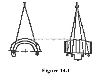
- Dry the kiln tire shaft carefully and apply a very thin layer of marking ink (it can be oil paint Prussia blue colored) along all the trunnion shaft length and with a width covering approximately 120°.
- Dry the bearing – fastened in the bucket – and place it carefully in the kiln tire, at the same time that, the pressure ring is utilized as guide when performing the lowering (or placement).
- Push the bearing forward and backward with short axial movements (10-12 mm) as long as it rests over the trunnion shaft. Control the clearance between the bearing and the trunnion shaft, as illustrated in Figure 14.2.
- Elevate the bearing and bucket by removing them from the trunnion shaft and control the foundation between the trunnion and the bearing to inspect blackening or spot of marking ink in the bearing.
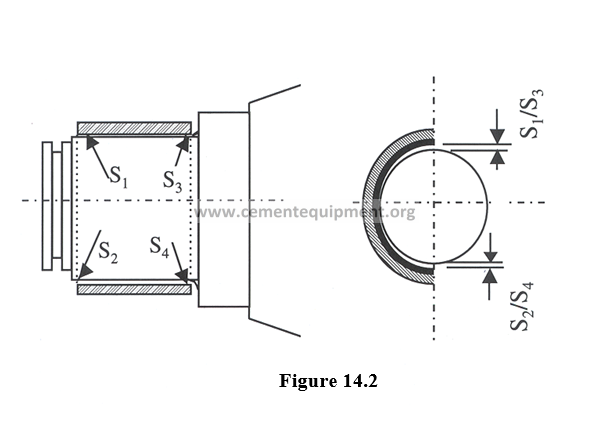
- If the contact is shown as a narrow strip interrupted or partially interrupted at the back of the bearing, it means that the foundation is satisfactory. See Figure 14.3.
If the contact is only shown as sporadic spots, the projecting parts regarding the bearing must be removed through slight scrapping and repeating the process until a satisfactory result is obtained.
- Subsequently, control that the transitions between the oil channels and the support faces of the bearings are leveled. When everything has been controlled and approved, the same type of oil as the one utilized for support is poured. The tire is placed in the correct position, and the support mounting operation is finished. Apply joint paste in all the union faces in order to get the bearing watertight.
14.3.4 Interpretation of results
The results under this procedure must be positive and when the new bearing is correctly installed, the kiln will be working satisfactorily.
14.3.5 Safety aspects
It is always dangerous to work close to a rotary kiln. Because it is required to work very close to it, appropriate clothing, safety goggles, safety shoes, gloves and safety shield must be utilized.
14.3.6 Condemning or permissible limits
In this procedure only successful bearings changes must be made related to the kiln running, and maintaining the bearing temperature within the range established by the manufacturer.
14.4 COMMENTS AND OBSERVATIONS
The development of a bearing replacement activity, is a job requiring persons with long experience, therefore they must be consulted when required by this procedure execution.
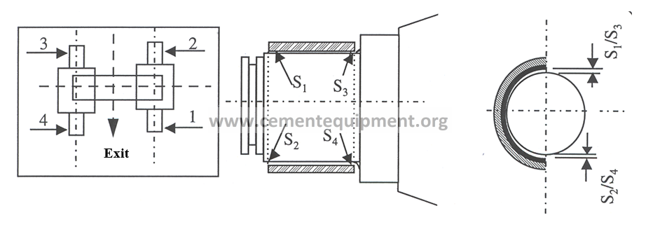
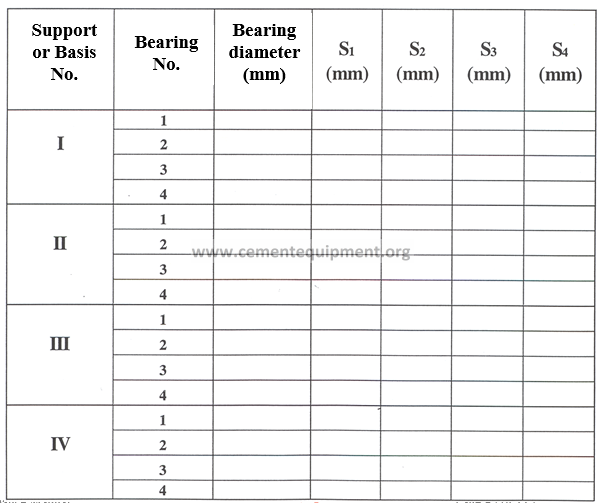
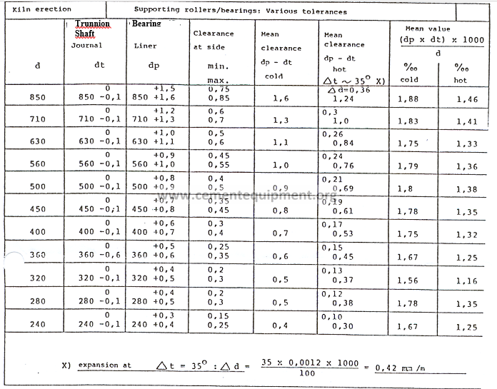
Chapter 15 KILN WELDING APPLICATIONS ANALYSIS AND CONTROL
15.1 OBJECTIVE AND SCOPE
The main objective is counting with directives about how to conduct rotary kiln shell welding applications inspections, as well as kiln tubes with satellites cooling system, or implant it.
15.2 METHOD BASIS OR FOUNDATION
The rotary kiln is a dynamically affected construction, because it consists of plates of different thickness welded between them.
Considering the kiln size and its running form (spinning in few supports), the multiple welding applications are subject to long and varied stresses.
When there is a normal operation, such as a kiln shaft replacement, etc., excessive loads can result on certain welding applications. Whenever these abnormal conditions continue for a long period of time, the cracks risk increases, especially in terms of cracks under fatigue inside the welding applications, and around the most critical welding applications in terms of stress loads.
Therefore, it is fundamental to check the welding applications periodically, visually and with penetrating liquids, magnetic particles, and / or ultrasound.
All the kilns but especially those with planetary or satellite cooling system, containing more welding applications subject to stresses loads, the following are considered as the most critical in terms of stress:
- All the unions in transition between the heavy section (or kiln shell) and the adjacent unions. Especially in the supports around the burning zone and in the cooling tube suspension arrangements.
- The welding applications at the kiln exit (reinforcement frames).
- The satellite cooling tubes arms welding applications.
- The reinforcement welding applications around the man entrance frames.
- The welding application of tires saddles or supports of the kiln tires.
15.3 METHOD DEVELOPMENT
15.3.1 Equipment and tools to be used
15.3.1.1 Inspection
– Wire brush
– Polisher – Hammer
– Penetrating liquids, magnetic particles, and / or ultrasound
15.3.1.2 Repairmen
– Punch
– Arch – air equipment, with 8 mm carbons – Welding AWS 7018
– Welding dry kiln
15.3.2 Periodicity
The union welding applications can only be examined with the kiln out of operation or shutdown during a determined period of time, thereby try to perform these activities in a time of shutdown scheduled by production or maintenance area.
The welding applications inspection frequency will depend upon the kiln operation. It must be made every two years under normal operation conditions.
When the operation conditions are abnormal, the load stresses are increased on the union welding applications; therefore the welding applications most exposed to these additional stresses must be inspected.
Every welding application repaired, must be reviewed subsequently every 6 months of kiln operation.
15.3.3. Procedure, calculation method and results
15.3.3.1 Visual inspection
The visual inspection of kiln welding applications is the simplest and most important inspection in order to know the conditions of a welding application.
At the same time of the visual inspection, a general checking must be made without removing rust or dirt of the welding application, because many times it is easier to identify the cracks possibilities in a not cleaned welding application.
After this initial inspection, the welded union surfaces are carefully cleaned, by using a hammer and a wire brush, and in sometimes a polisher can be required.
Caution must be observed to never confuse the irregularities of a crack welding application.
It is recommended that the unions welded are inspected with penetrating liquids, or with methods related to magnetic particles, ultrasound, or with another more advanced. method and / or equipment
15.3.3.2 Penetrating liquids test
The penetrating liquids are substances with intense color (normally red), that when applied to a metallic surface, penetrate in every crack, and through the usage of a developer the evidence of a cracks will increase.
This method is performed in the following form:
- Remove the grease and dirt from the surface.
- The penetrating liquid is applied in the same way as you were painting with spray over the clean area and with a uniform layer (not spilling liquid).
- Let the liquid penetrate in the possible cracks. Ten (10) minutes are sufficient at a temperature of 0 to 60° C.
- The penetrating liquid excess is carefully removed with a piece of cloth or rag. If the liquid is soluble in water, it must be used, otherwise a cleaning liquid must be used.
The penetrating liquid must never be removed by spraying water or cleaning solvent directly, the cleaning operation must always be done with the rag or piece of cloth moisted, observing that fluff is not generated.
- Wait until the surface is dry, and then apply a thin layer of developer, this is a high absorption dust, suspended in a volatile solvent.
- After the solvent is evaporated, the possible cracks will appear with a strong appearance in form of red lines contrasting on a white base.
Important is that when the cracks are full of grease, oil, etc., this method cannot be utilized.
In this case the magnetic particles method must be utilized.
There where the cracks are extremely deep, the penetrating liquid will penetrate so deep, that the developer will not function. Assure that sufficient penetrating liquid is applied and provide a reasonable time period for penetration.
At temperatures below 0°C the plate requires to be preheated with a gas burner or a blowtorch or with hot air and this before the penetrating liquid application.
15.3.3.3 Magnetic particles method
The magnetic particles and magnetic dusts methods are performed covering the area to be examined by ferromagnetic indicating material (magnetic dust).
A magnetic field is generated in the area, at least in two directions with the highest degree of perpendicularity between them.
The indicating material will not be accumulated in the cracks, and this incompatibility will show the surface region defects, the defects extend up to 3 mm below the surface.
In order to make the cracks identification easier, before examining, all the area must be painted with a light of contrasting color.
The inspection with magnetic particles must be performed in a way that the magnetic field efforts in the area to be examined are within the 2,400 to 4,000 A/m (30-50 Oersted) range. The simplest method is the usage of an electromagnet with 90° change of phase.
The undermining must be avoided with the magnetization method
15.3.3.4 Ultrasonic inspection
The ultrasound inspection can be performed in case of fissures or internal failures of the unions welded, in the suspected areas, or where the crack depth must be assured previous to its repair.
The ultrasound inspections must be made after the welding application is repaired.
Normally an ultrasound inspection can be performed with angular testers of 4 MHz at 45° and 70° and with normal testers of 2 Mhz.
15.3.3.5 Repairmen
Whenever a crack is discovered, the most appropriate method of repair must be determined.
The cracks with a length lower than 10 mm rarely have a depth exceeding 3 mm. Such “minor cracks” can normally be eliminated with a polisher.
This form of repairmen is sufficient if it is possible to remove the crack by polishing or rabbeting the material, not reducing the thickness more than 3 – 4 mm or higher than 10 % of the plate thickness, as long as it is polished, at the same time, the surface must be clean, without splits and with a minimum radius of 15 mm.
It must be inspected later with magnetic particles, as higher grinding application can be required.
Welding application must repair the major cracks, cracks supposed to have a depth deeper than 3 mm.
Along with the welding application repairmen, these directions must be strictly followed:
- Mark the crack length.
Mark all the crack length through a punch by marking the crack ends with a dot, so that the welding operator is capable to identify the dot where the welding application will begin.
- Preheating
Preheat the area of union to be welded at 100 – 150 °C.
- Welding Application
Arch – air must be applied on the welded union, from the cracks ends to its center. The carbon electrode thickness must be 8 mm, and the welding machine, must have as minimum 400 A power.
The welded union must be undermined as deep as the crack is totally eliminated. For passing cracks, the depth of the welded union must correspond to 75 % of the plate thickness.
On the base, the width of the welded union must be so that there is enough space left to deposit a good mooring, or base welding application.
The area to be welded must be perfectly polished, because a not proper polishing application will generate new cracks. A minimum 1 mm grinding application must be made, in order to eliminate every trace of carbon. The union must be totally clean from metal.
The union to be welded must be subject to inspection with penetrating liquids or magnetic particles. Not forgetting the sides of the welded union. In case of existing traces of cracks formation, they must be eliminated again and the repairmen process must be reinitiated.
The welding application is not ended, until eliminating every trace of defect or imperfection.
Subsequently a preheating of 150° minimum is performed. This temperature can be obtained through the welding process.
After the welding application is finished, it must be covered with mineral wool, or something similar, in order to minimize the cooling speed, which could cause generation of new cracks.
The welding operation is performed with dry electrodes AWS 7018.
The minimum electrode thickness to be utilized must be 3.25 mm (118°). This requirement is also applicable to the mooring, as well as to the welding operation.
As the electrodes are highly sensitive to the humidity, they must be maintained in a dry kiln at temperatures between 200 – 250°C at least 3 hours previous to be utilized. In the welding application place, the welding application must be maintained at 70 – 150 °C.
In case of having a passing crack, the previous procedure, is repeated, but now the other side regarding where just has made the welding application.
In order to minimize the appearance of new cracks, the welding application must be grinded, eliminating its convex face, leaving a smooth surface.
The repaired area must be finally inspected, in order to assure absence of cracks or defects.
15.3.4 Interpretation of results
The obtained results under this procedure must be positive, and the rotary kiln must be always without cracks so that there is not danger for personnel and / or machinery.
15.3.5 Safety aspects
It is always dangerous to work close to a rotary kiln. As it is required to work very close to it, appropriate clothing, safety goggles, safety shoes, gloves and safety shield must be utilized.
15.3.6 Condemning or permissible limits
There is not a permissible crack in the kiln. As soon a crack is detected, it must be immediately repaired.
15.4 COMMENTS AND OBSERVATIONS
The procedure for inspecting welding applications, as well as their repairmen must be made with highly qualified personnel, and with long experience, thereby sometimes if qualified personnel is not available in the plant, it must be contracted or the service must be requested to Technology Management.