Ball Mill Diagram: Parts, Components and Functions
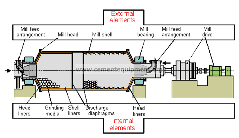
A cement ball mill consists of the shell, mill heads, trunnions, bearings, liners, diaphragms, grinding media and the drive train (motor, gearbox, pinion and girth gear). The diagrams below show where each component sits and what it does.
| Part | Function |
|---|---|
| Shell + liners | Contain the charge and control lifting/cascading action |
| Diaphragm | Separates chambers and controls material/air passage |
| Trunnion + bearing | Support rotation and transmit mill loads |
| Grinding media | Break and grind the material by impact and attrition |
| Drive train | Provides controlled torque and mill speed |
Useful next steps: ball mill parts and components procurement guide, ball mill critical speed, and cement ball mill maintenance.
Troubleshooting a real plant problem? Request a free cement plant technical assessment for your kiln, mill, cooler or other operating issue.
Ball mill labeled diagram: how to read the main components
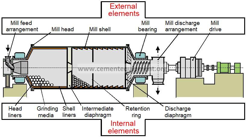
Use the first diagram as a component map. Material enters through the feed arrangement and inlet end, then moves through the rotating mill shell. Inside the shell, liners protect the body and lift the grinding charge; grinding media breaks clinker by impact and attrition; and the intermediate diaphragm separates the coarse and fine grinding chambers while controlling material and air passage. The bearing arrangement supports the mill, while the motor, gearbox, pinion and girth gear provide the torque needed to rotate it.
This page is the site’s diagram and visual-reference page. For procurement, wear items and spare-parts planning, use the Ball Mill Parts & Components Guide. For operating calculations, use the ball mill calculation formulas.
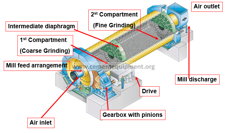
What is a End Discharge Mill (EDM)?
EDM =End Discharge Mill

Elements of Ball Mill – Overview
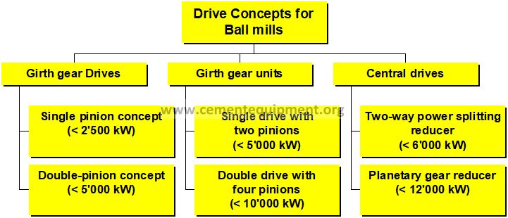
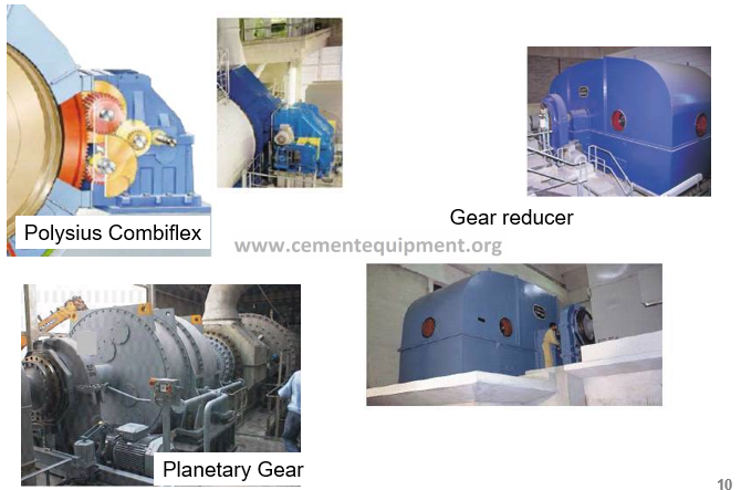
Mill Drive Concepts
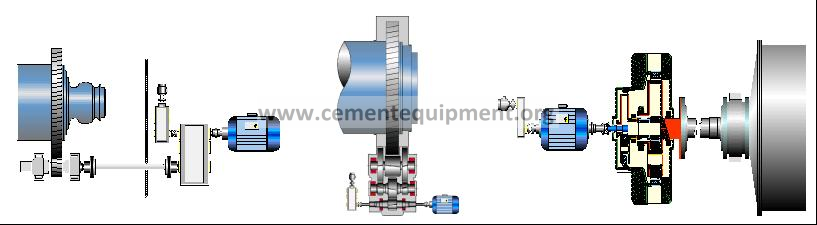
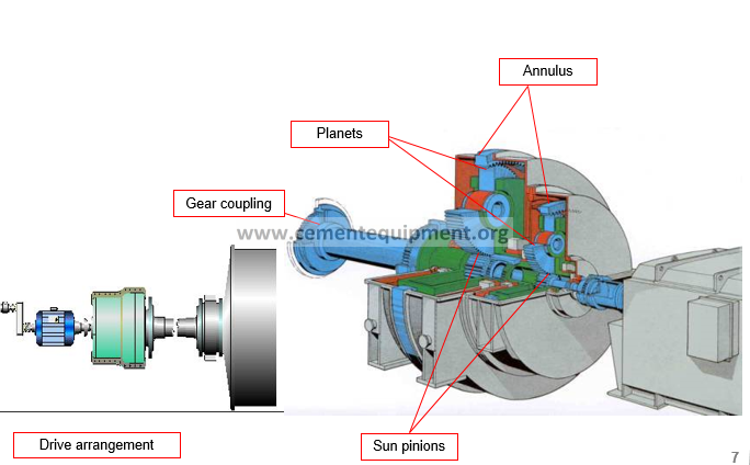
Example Planetary Gear Drive
Planetary gear reducer concept MAAG
-Two gear stages with three planets
-All shafts with friction bearings
-Pinions, planets surface-hardened
-Annulus through-hardened
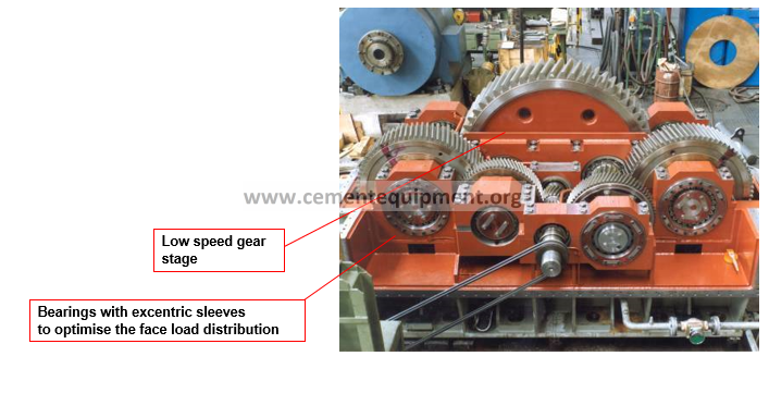
Gear Box Internals
Parallel shaft gear reducer (two way power branch)
– All gears surface-hardened and ground
-All shafts with roller bearings
-Key point:: Face load distribution of the LS-gear stage
Potential Technical Problems Drive
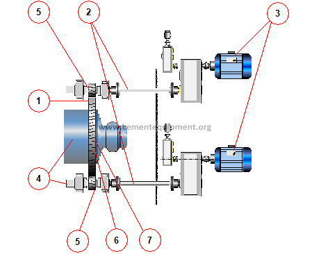
Girth gear drives – Fundamental Problems
1.Axial/radial runout
2.Alignment of the drive trains
3.Uneven power splitting
4.Centre distances variable
5.Face load distribution
6.Sealing of the girth gear
7.Girth gear is through hardened only, fatigue strength is limited
-Dynamic behaviour
-A lot of individual rotating masses risk of resonance vicinities
-Torsional/structural vibrations
-Pinion shaft bending vibrations
Gearboxes
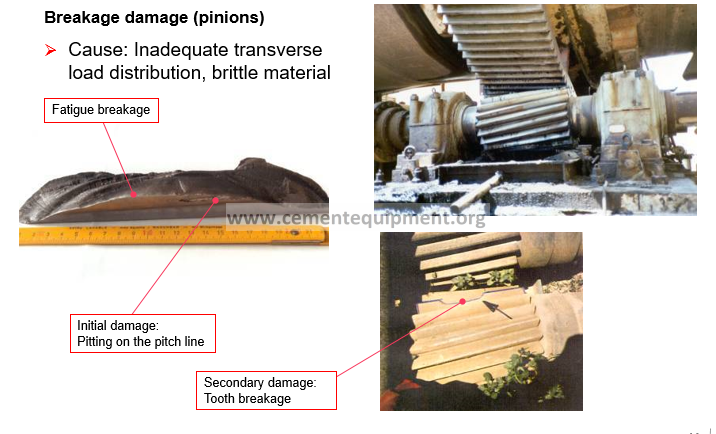
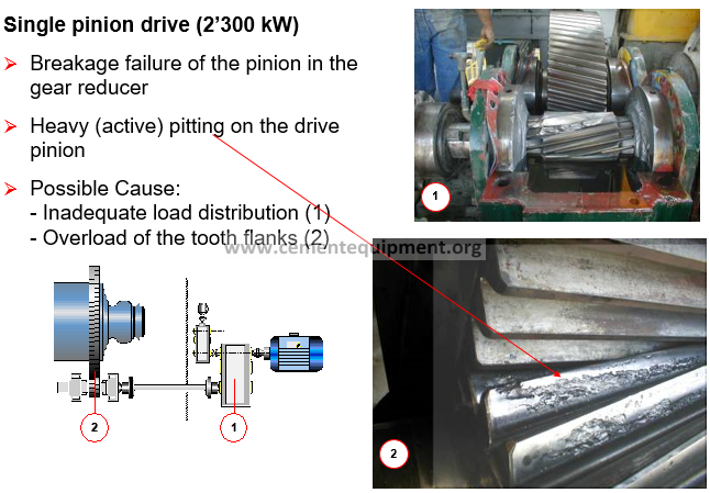
Potential Damages Drives
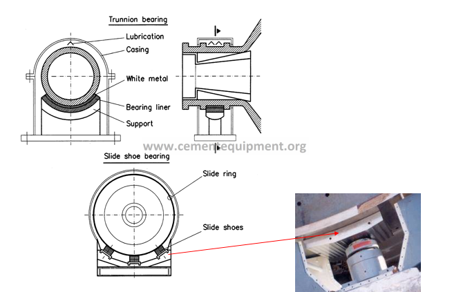
Mill Bearing
Advantages slide shoe bearings:
- No size and capacity limitation of the mill
- Simple design of wear plates
- Far higher limit of gas temperature at mill inlet (e.g. for drying with heat generator)
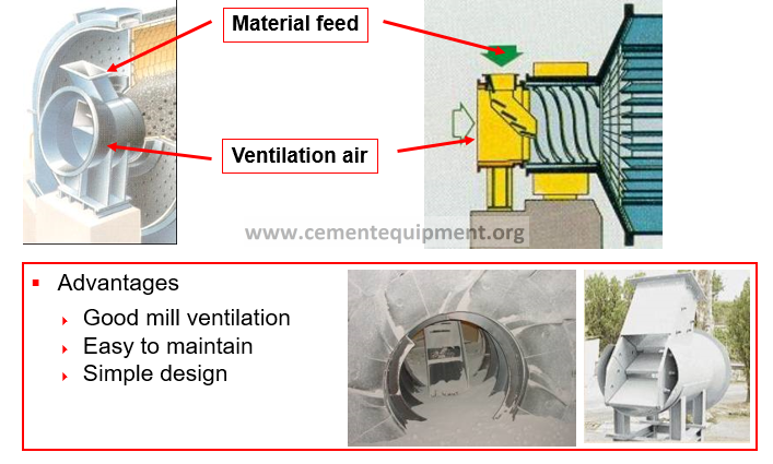
Feed Arrangements for Ball Mills
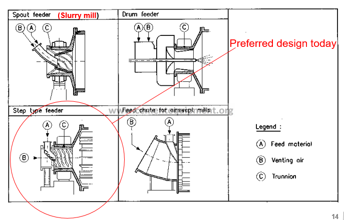
Feed Arrangement (Example Step Feeder)
Elements of Ball Mill – Overview (Internals)
Overview Internal Elements
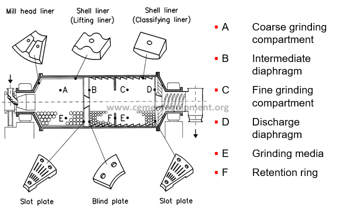
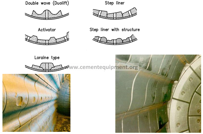
Liners for Coarse Grinding
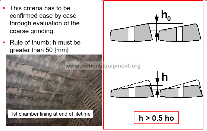
Lifting Height Requirements (1st Chamber)
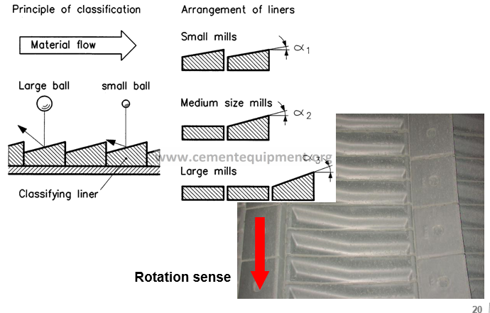
Classifying Liner for Fine Grinding (2nd Chamber)
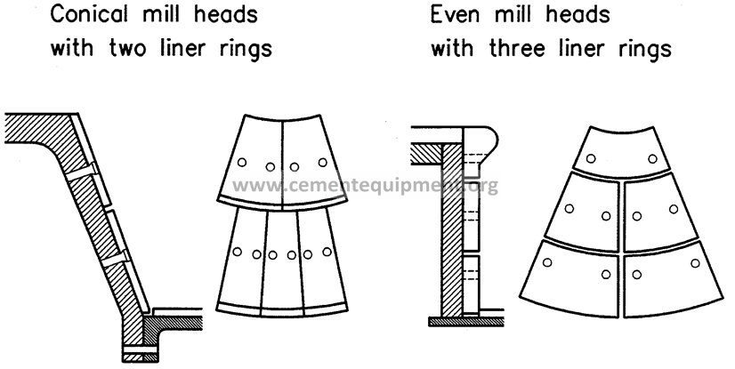
Head Liners
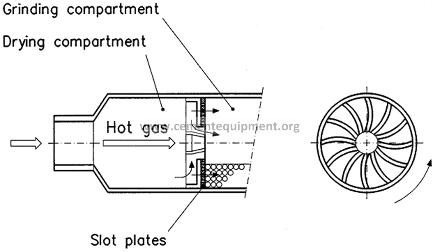
Open Diaphragm (Drying Chamber Diaphragm)
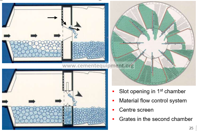
Intermediate Diaphragm
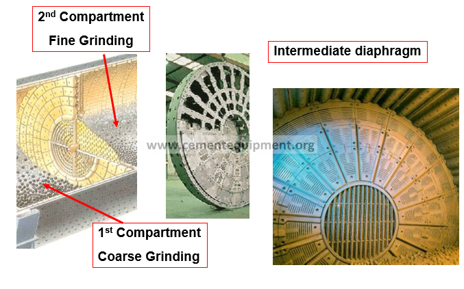
Function of Intermediate Diaphragm
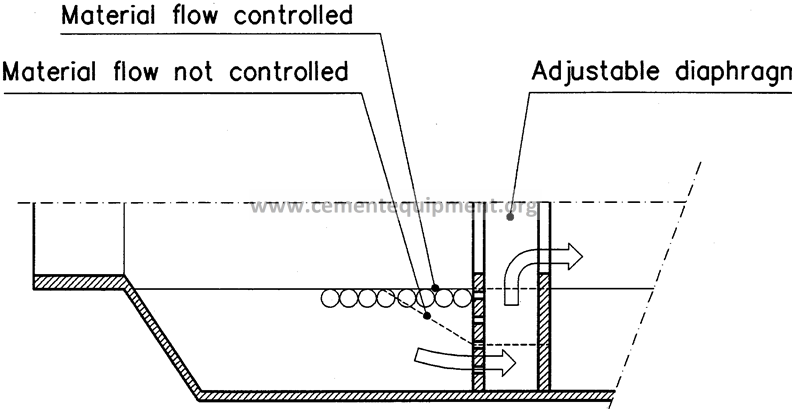
Intermediate diaphragm
Discharge diaphragm
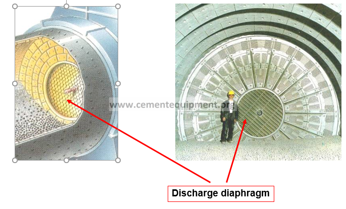
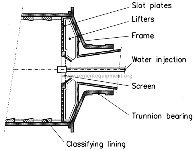
Discharge Diaphragm
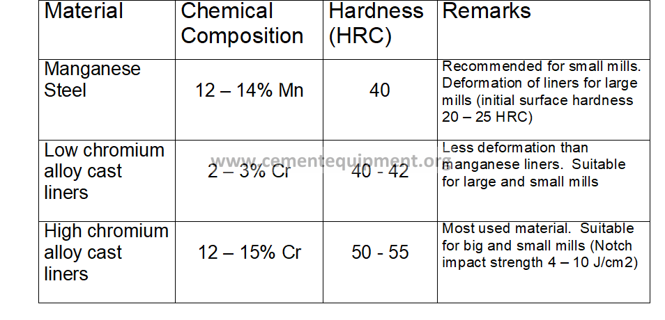
Material Quality and Application of Shell Liners
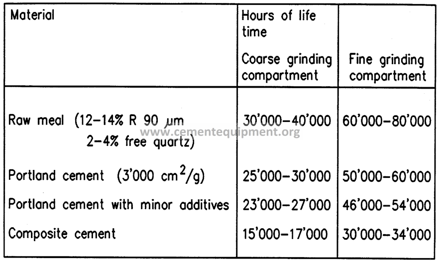
Life Time of Shell Liners
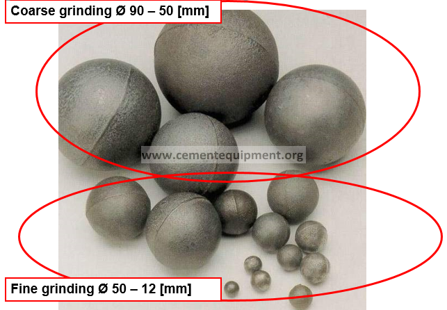
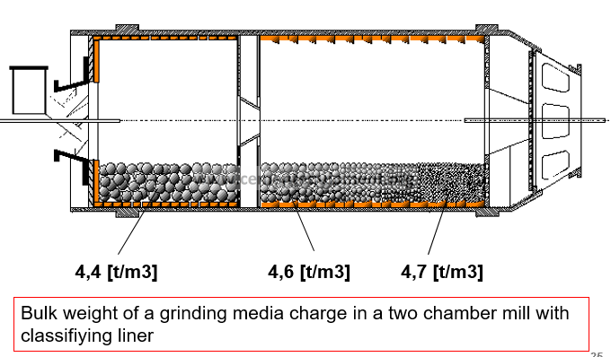
Grinding Media
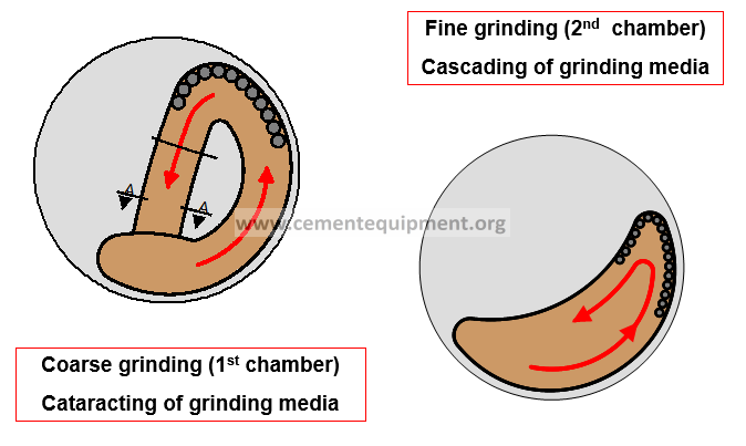
Grinding in Ball Mill
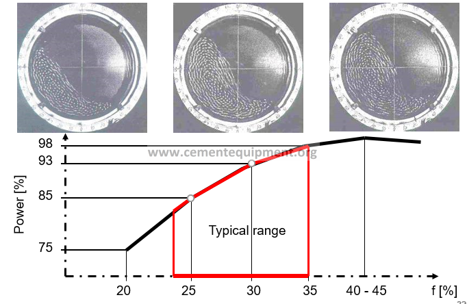
Ball filling degree (f)
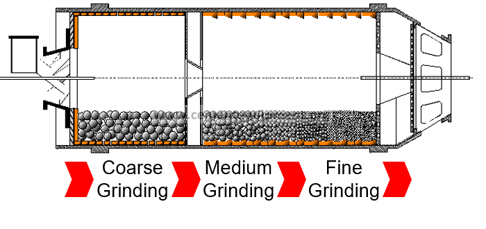
Steps of Grinding
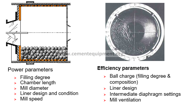
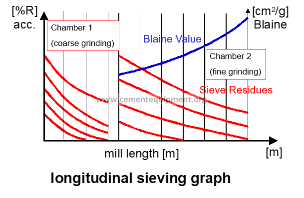
Coarse Grinding: Parameters for Optimising
Grinding Media
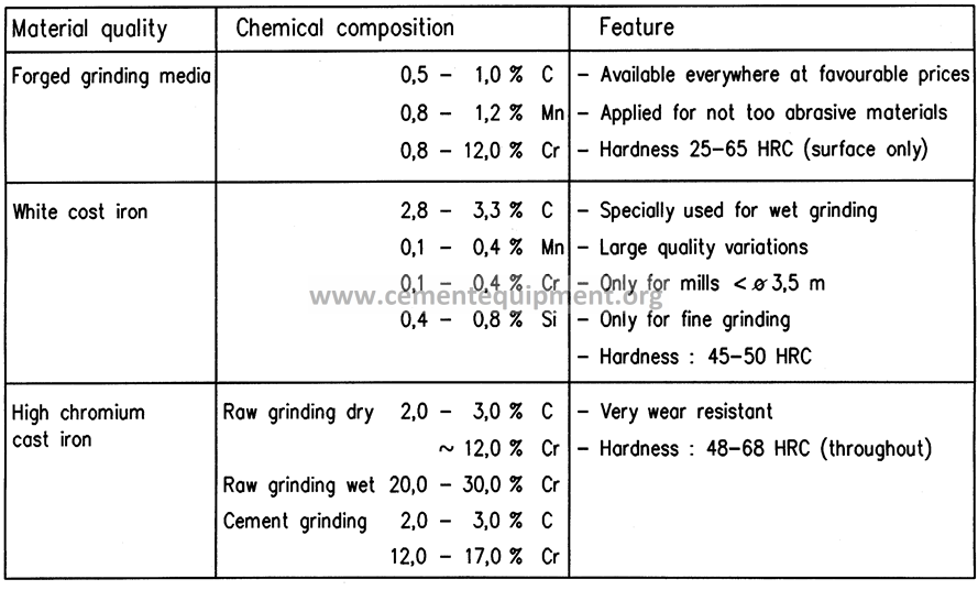
Material Quality of Grinding Media
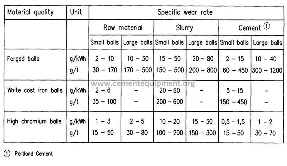
Specific Wear Rates of Grinding Media
Mill Efficiency
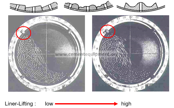
Lifting Liners Effects
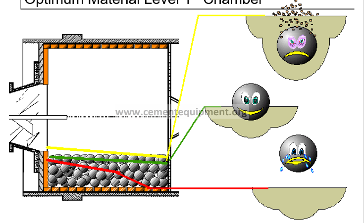
Optimum Material Level 1st ChambeR
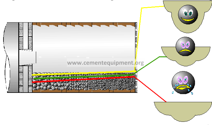
Optimum Material level 2nd chamber
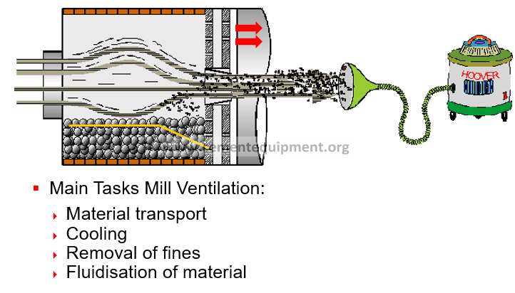
Mill Ventilation
Cooling and Heating Possibilities
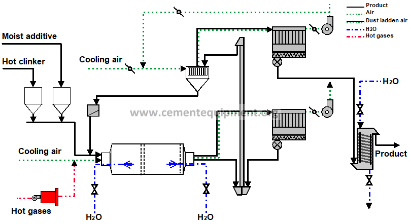
Fine Grinding and Mill Cooling
PROBLEM
Insufficient mill cooling lead to material agglomeration on balls and liners
The grinding is not any more done by balls against material but by material against material
SOLUTION
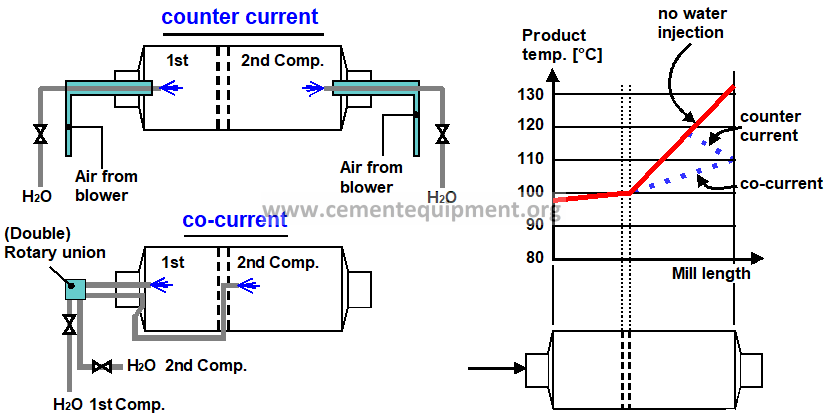
- Adapted mill cooling, playing with:
-Water injection
- Use of grinding aid (temporary solution because expensive)
Water Injection Systems
Please we are in need to catalouge for grate plate