Contents
Suspension preheaters with precalciner
TO DOWNLOAD THE EXCEL SHEET AND ALL THE OTHER USEFUL BOOKS AND RESOURCES KINDLY CLICK HERE

The SF-suspension preheater of the IHI
In the early 1970s the Ishikawajima-Harima Heavy Industries Co., Ltd., Tokyo, Japan (abbrev. IHI) mar keted a new development of the cyclone suspension preheater. The essential factor of this new preheater or preheater process (which the IHI calls SF-Process*), is that most of the calcining of the raw mix is per formed separately in a so-called “Flash furnace”, where the lowest temperature difference between gas and raw mix particles is applied. The clinker burning process itself is performed in a relatively small rotary kiln with an appropriate retention time. Whereas in a regular suspension preheater the raw mix is only slightly calcined (about 20 %), it subsequently requires about two thirds the length of the rotary kiln for the calcining, and the remaining one third for clinker burning. IHI started from the principle that the rotary kiln is an economic heat exchanger only in the area of the burning zone, where heat transfer is mostly accomplished by radiation. In the colder part of the rotary kiln, i. e. in the calcining zone the heat transfer is no more expedient. The heat transfer pro cess can be shaped more economically by suspending the raw mix particles in the gases. The SF-process solved this problem by creating the flash furnace, in which the raw mix is calcined up to about 90 %; in this state the raw mix is then fed into the rotary kiln. In this way, when compared with the regular suspen sion preheater kiln, the required heat supplied to the rotary kiln can be reduced roughly by 50 %. How ever, to be able to operate the kiln with th usual gas velocity, the heat quantity supplied into the kiln can be volumetrically doubled; the result will be a corres ponding incr ase in kiln capacity. According to IHI only 40 % of the total heat is supplied into the rotary kiln; the remaining heat quantity is supplied into the flash furnace.
Fig. 20.21. shows a graphic comparison between the regular raw mix suspension preheater and the SF-process.
At the present time, the following preheater sizes are supplied by the manufacturer (see Table 20.4.).
Fig. 20.19. shows the arrangement and the mode of operation of the countercurrent raw mix preheater of the Prerov Engineering Works (Czechoslovakia).
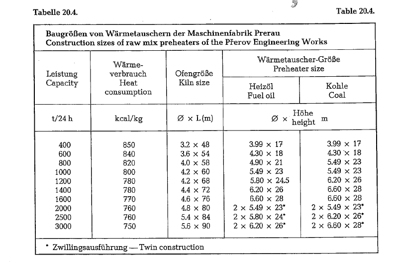

Fig. 20.21. shows a graphic comparison between the regular raw mix suspension preheater and the SF-process.

Specific kiln capacity of the SF-process
The highest specific kiln output attained by a regular cyclone suspension preheater is 1.93 shtons/m3 · 24 h
referred to the effective kiln volume measured on bricks; by increasing the kiln revolutions, specific kiln capacities of 2.53 shtons/m3 · 24 h were recently revealed. According to reports from IHI, a specific kiln capacity of 3.63 shtons/m3 · 24 h was attained with the SF-process. In this way high kiln capacities can be attained with a smaller diameter and shorter kiln. Shipment of such kilns to the construction site will be easier. A smaller rotary kiln requires a smaller construction lot; compared with a regular preheater kiln, an SF-kiln requires roughly 25 % less construc tion place for the same capacity with a slightly increased height of the preheater structure.
A smaller rotary kiln with a high throughput shows lower specific heat losses by radiation and convec tion; this is the reason that the heat consumption of the SF-process is quoted to be 5-10% lower, when compared with the regular suspension preheater kiln.
According to the manufacturer, some of the main advantages of the IHI precalcining system are:
- Smoother Flushing of the material in the kiln is greatly reduced; the major cause of flushing is the non-uniform release of the carbon dioxide gases (calcination). Most of the gases are released in the flash furnace.
- Improved refractory life for the This is due to fewer and smaller thermal strikes resulting from the decreased frequency of kiln flushes. Plus, for a given capacity the smaller kiln affords better physical stability of the lining through a smaller-arc with better keying action. Net result is a con siderably lower consumption of kiln refractory.
- Since most of the fuel is burned at low tempera ture in the flash furnace, the generation of nitro gen oxides is reduced to levels less than half of those encountered in conventional suspension preheater kiln

The suspension preheater process designated as the SF-process, is schematically shown in Fig. 20.22. (Fuller Co. Bulletin PR-3).

Data of an SF-Suspension preheater unit


Numerous tests as well as heat and fluid dynamics measurements resulted in the shaping of the flash furnace, which renders a fast and intensive heat transfer from the gases to the raw mix particles, avoiding simultaneous coating of the material on the walls. Fig. 20.23. shows temperature distribution curves of three various cross-sections through the flash furnace; the figures refer to o Celsius.

The kiln exit gases are mixed with the clinker cooler’s center exit air and are thus cooled before entering the flash calciner; for this purpose the tem perature of the center exit air from the clinker cooler is in the range of 650-705 o C. In this way compo nents of the kiln exit gases condense on raw mix par ticles and are then returned into the kiln, thus avoid ing coating on the walls of the flash calciner.
The above mentioned mixture of clinker cooler cen ter exit air and kiln exit gas arrives with strong tur bulent flow from the vortex chamber into the reac tion compartment.
Fig. 20.24. is an illustration of a recently developed SF-process. The flash furnace itself consists of a vor tex chamber (lower part) and a reaction chamber (upper part). A most recent development is to divert a portion of the flash furnace feed down into the riser duct just above the kiln feed hood. Components of the kiln exit gases condense on this diverted raw mix, thus minimizing the coating on the walls of the riser duct.
Fig. 20.24. shows also the flow pattern of the SF-pre calciner. The major part of the gases from the vortex chamber flows up along the wall of the reaction chamber with a spinning movement together with the raw mix particles. This mixture of gases and parti cles completes many revolutions while rising upward to exit at the gas outlet duct.

Because of the vortex action, a negative pressure region is developed along the axis of the chamber. The raw mix and fuel are introduced into this nega tive pressure region. Thus, mixing and dispersion of the raw mix and atomized fuel particles with gases takes place. As the fuel particles are burned, the developed heat is transferred immediately to the raw mix particles, thus producing a calcination of roughly 90 %. Therefore, a luminous flame of combustion gases as seen in the rotary kiln is not observed in the precalciner. In fact, about 90 % of the heat is trans ferred by forced convection, while only 10 % by radiation.
The flash furnace diameter of a 3500 t/24 h SF-pre heater unit is 7.4 m; a 4000 t/24 h capacity unit shows a diameter of 8.2 m. The height of a flash furnace equals the cyclone height of the lowest preheater stage.
Fuller Company as a licensee of IHI, supplies SF-flash calciners to various parts of the world. Due to the fuel oil crisis of the 1970s, the Fuller Company developed a coal dust firing system for application to the SF-flash calciner
SF-precalciner with coal firing
Almost all plants are now being constructed using coal dust firing for both the rotary kiln and the pre calciner.
The flash furnace operates in a temperature range of 830-910 oc (see Fig. 20.20.); to prevent build-up due
to molten coal ash, any coal whose ash melting point is above 1100 o C, can be applied. The characteristics required -such as heating value, ash content, vola tility, and fineness – are similar to those specified for coalfired rotary kiln burning systems.
Preheater exit gases whose oxygen content is gener ally below 5 %, are supplied to a roller mill for drying-grinding and conveying of the pulverized coal. The coal is stored in explosion proof vessels, whose storage capacity is limited to the equivalent of 15- 30 minutes of coal feed. The carrier gas is cleaned in a dust collector whose oxygen content is monitored continuously.
The coal is metered to the rotary kiln and flash fur nace separatly as required by their respective burn ing conditions. The flash furnace employs several burners; therefore, a splitter serves to divide the coal laden gas stream equally to each particular burner
The SF-precalciner with bypass
The process itself and the necessity of bypassing rotary kiln exit gases.
The utilization of a kiln bypass causes heat losses in the amount of about 4 kcal/kg clinker for each per cent of bypass. This heat is reduced substantially in a precalcining system, provided that the precalciner receives its hot air via a separate duct from the clinker cooler rather than through the kiln. For example, in the SF-precalcining process, the heat loss is reduced to 2 kcal/kg clinker per percent of bypass volume. As shown in Fig. 20.22., 60 % of the total fuel is burned in the flash furnace, and only 40 % in the rotary kiln. The undesirable components are volatil ized in the rotary kiln rather than in the precalciner; therefore, a given quantity of these components can be removed via the bypass with a reduced volume of kiln gas. Furthermore, as the quantity of bypassed kiln gas is increased, the additional fuel is introduced through the precalciner, which is located after the bypass port. This characteristic permits the precalci ner system to operate at bypass levels up to 100% [251c]. About precalciners with 100% bypass for low alkali cement see also chapter 20.9.5.
The MFC-suspension preheater
The MFC (abbreviation from .Mitsubishi Fluidized Calciner) suspension preheater consists of a regular raw mix suspension preheater (system Dopol, Poly sius), working in conjunction with a fluid bed calciner. This suspension preheater was developed by the Mit subishi Mining and Cement Co., Ltd., in cooperation with the Mitsubishi Heavy Industries, Ltd. [259b].
With this process, the calcining of the raw mix is per formed in a separately heated fluid bed reactor, which is located between the suspension preheater and the rotary kiln; Fig. 20.25. shows a schematic of this arrangement. The first MFC suspension prehea ter was erected in the Higashidani Cement Plant of the Mitsubishi Mining and Cement Company. Later two other MFC suspension preheaters were erected; in the Kurosaki Cement Plant, and in the Kanda Cement Plant of the Mitsubishi Mining and Cement Company:


MFC-Fluid bed reactor: 4.0 m dia. x 4.5 m high Fluid bed blower: 650m3/min, 350 °C, 1800 mm W.G. Fluid bed blower motor: 240 HP Pressure drop through MFC preheater: 1200 mm W.G.
The heat consumption of the total system is quoted to be 781 kcal/kg of clinker; although the heat consump tion does not differ from that of a regular suspension preheater, Mitsubishi intends to improve the extrac tion of air from the clinker cooler with the goal to lower the specific heat consumption.
The heat balance of an MFC preheater is given as fol lows:

The RSP-suspension preheater
The RSP-suspension preheater (abbreviation of Rein forced Suspension Preheater) portrays a modification of the lowest gas duct of a regular suspension prehea ter; it consists essentially of a two-compartment calci ner, i.e. of the proper heating shaft supplied with a swirl burner, and of the calcining shaft, arranged about parallel to the heating shaft. This arrangement is schematically shown in Fig. 20.26.
The RSP-suspension preheater is a joint development of the Onoda Cement Company, Ltd., and of Kawasaki Heavy Industries, Ltd. Tokyo.
Combustion in the heating shaft is maintained with the hot, so-called center exit air of the clinker cooler. The raw mix coming down from the second stage of the preheater distributes itself evenly in the combus tion gas of the heating shaft, into which it drops down; after meeting the hot kiln exit gases, the raw mix is lifted in the ascending gas duct, called calcin ing shaft, from where it enters the cyclone of the first stage. The suspended raw mix is then calcined at a rate of 90-95 % before entering the rotary kiln. Thus the activity of the rotary kiln is, as in the above des cribed processes (SF- and MFC-suspension prehea ters), limited to the actual sintering process; this increases the capacity of the rotary kiln considerably. Onoda-Kawasaki claim that the kiln’s sintering or throughput capacity is 2.5 to 3 times higher than that of a regular preheater rotary kiln; thus smaller rotary kilns show higher capacities. It is said that capacities of 6- 8000 t/24 h can be attained with kilns having daimeters in the range of 5-5.5 m.

The gas exit temperature from the calciner shaft is 950 oc and the raw mix temperature at the kiln entrance is 820- 840 o C; this temperature is only slightly higher than that in regular suspension pre heater kilns; nevertheless the degree of calcination with the RSP-process is in the range of 90-95 %.
The rotary kiln is supplied with about 30- 45 %, and the swirl burner of the calciner with 55- 70 % of the total heat assigned to the RSP-preheater. Since the rotary kiln is supplied with less heat, it requires a correspondingly lower amount of secondary air; thus a sufficient quantity of hot air from the clinker cooler can be supplied to the swirl burner.
The specific heat consumption of an RSP-unit with a capacity of 3000 t/24 h is reported to be 760 kcal/kg.
In America, the Allis-Chalmers Company manufac tures the RSP-preheater under a license agreerilel).t with Onoda Cement Co., Ltd., Japan. ·
The Polysius precalcining process
When developing its own precalcining method, the Polysius Company tried to simplify the process, i.e. to achieve the same precalcining effect, no matter what kind of cooler would be applied. This problem was solved in cooperation with the Rohrbach Company in Dotternhausen, Germany.

The basic idea of this method was to place the com bustion of fuel necessary for precalcining of the raw mix in a connecting duct between the rotary kiln and the preheater, and to draw the required combustion air through the rotary kiln, together with the combus tion gases. Polysius claims that the advantage of this method is the elimination of all additional air convey ing ducts with all the control problems involved, this process also allows the application of all cooler sys tems, even such coolers as e.g. planetary coolers.
Fig. 20.27. shows schematically the conventional method of conveying the clinker coolers hot exit air through a separate duct to the precalciner.
Fig. 20.28 shows the Krupp Polysius arrangement, where the combustion air for the calciner is drawn through the rotary kiln. After passing a dust collec tion cyclone, the kiln exit gases enter a 4-stage cyclone suspension preheater.
Fig. 20.29. shows the lower stage of a Dopol preheater with precalciner arrangement. From the Dopol-tur bulence ·shaft, the raw mix passes an ascending duct where the heat from the fuel supplied through sev eral burners causes extensive calcining. After separa tion in the lowest cyclone stage, the raw mix enters the kiln feed hood. The length of the calcining duct is designed to guarantee complete combustion of the fuel down to the entrance of the lowest cyclone stage. With a size reduced rotary kiln, the size of the cooler for the clinker capacity remains unchanged.
For a precalcining rate of 90- 95 %, the correspond ing excess air figure is 2.05, with a flame temperature in the rotary kiln of about 1800 °C, in contrast to 2200 o C when running without precalcining. Even under these conditions the heat transfer in the rotary kiln is no problem. The rotary kiln exit gases show an oxygen content of 12 %, before entering the calcining duct.
As to the gas velocity in the rotary kiln, Krupp Poly sius presents the following comparison: In a rotary kiln of the size 4.2 x 66 m, working in conjunction with a precalciner, the gas velocity is approximately only 12% higher than in a kiln with the same capacity but working without precalciner; in this case however, the kiln’s size would be 5.0 x 82 m. It is fur ther stated that by appropriate shaping of the kiln’s inlet and burning hood, it could be easily possible to run a precalciner kiln with practically the same gas velocity at the kiln’s inlet, as a correspondingly larger kiln working without a precalciner system, despfte , the higher specific throughput and the reduced diam eter of the precalciner kiln.


The described Polysius-precalciner method is charac terized by a combined passage of combustion gases and air through the rotary kiln’s cylinder and is capa ble of working in conjunction with any kind of clinker cooler; this system serves for a longer period of time in industrial operations. Taking into account the heat and the kWh consumption, the investment costs, and the specific prices for refractory lining of large rotary kilns, an economy calculation shows that kiln capacities resulting in savings of operating costs start at the 2500-3000 metric t/24 h level. At very high kiln capacities, savings are said to be considera ble [259d, 259e].
An arrangement with a separate hot air duct from the cooler to the pecalciner is designated by Krupp Poly sius as AS (Air Separate), with an arrangement where the total combustion air passes the rotary kiln is called AT (Air Through). Precalciners are designated by .Polysius as “Prepol”. Prepol precalciners can be constructed as Prepol AT (Fig. 20.29.), and as Prepol AS (Fig. 20.27.).
In contrast to the PREPQL® AS process, in the PRE POL® AS-LC arrangement (Fig. 20.27.a.) the tertiary air is accelerated to a high velocity at the calciner inlet. The two tertiary air streams enter the calciner shaft offset from each other sideways. Thus, one can opti mally control the mixture of fuel particles and com bustion air at minimal pressure drop. The combustion velocity is accelerated and complete combustion assured.

The fuel can be fed before, simultaneously to or after the raw meal in the calciner as desired. Depending upon the fuel and raw meal characteristics the cor rect processing temperature can thus be established.
Thus, according to Krupp Polysius, the PREPOL® AS-LC process permits the cost effective use of high ash and low calorie fuels and fuel mixes.
Which kind of precalciner, i.e. a Prepol AT, AS or a Prepol AS-LC (Low Grade Combustibles) should be applied in a particular case, depends on a feasibility study [259m]. A precalciner model Prepol AS is shown in Fig. 20.29.a.
This precalcining system is characterized by a special air duct which conveys hot combustion air from the grate clinker cooler to a separate precalciner, which is described below. In large production units with raw mix suspension preheaters designed as a twin system, the exit gases from the precalciner, and the exit gases from the rotary kiln are each led into one separate preheater line. According to the manufacturer, this system shows the following advantages:
- As at all other precalciners, the kiln dimensions can be considerably reduced.
- The precalciner can be supplied with combustion air from the clinker cooler at a temperature of approximately 900 oc, since the control devices are located in the gas stream behind the prehea ter; this arrangement guarantees full control of the combustion air.
- The process control allows for a suitable margin of safety against overheating, even at a precalcining degree of 90- 95 %.
- Start-up operation of the kiln and the appertain ing cyclone preheater line is carried out in the usual After these two units are in regular operation, the precalciner and its cyclone preheat er line are switched into operation.
- The high degree of precalcination and the regular feeding of the kiln ensure stable kiln operation without kiln upset
- For removal of chlorine, alkalies, and sulfur, a bypass can be easily attached to the system caus ing only moderate heat
In the “Dania”-system, the content of the volatile components from the preheater into the kiln is consi derably lower than in a conventional preheater sys tem. The sulfur content increased by the part which was introduced into the system with the fuel. Further, it should be noted that the specific heat consumption of the “Dania”-kiln is somewhat higher than that of a conventional preheater kiln, since in this case the preheater exit gases were not fully utilized.


Fig. 20.33. Kiln-preheater recirculation diagrams of volatile components of the ‘Dania”‘ wet-dry process
The precalciner quoted in the above described pre calcining systems is shown in Fig. 20.34. Its design is extremely simple, and consists merely of a refractory lined cylinder with conically shaped top and bottom. The characteristic feature of this precalciner is the thorough blending of raw mix and fuel prior to introduction of combustion air” and subequent initiat ing of the combustion process. An effective blending of preheated raw mix and pulverized or gaseous fuel is a relatively simple operation. With oil as fuel, the oil is generally introduced just below the calciner by means of air atomizing burners. Natural gas is simi larly introduced by special nozzles. Coal enters through the bottom of the calciner by screw conveyor or injection.

The precalciner can be operated with fuel oil, coal, natural gas, and also with oil shale of low calorific value.
The combustion air is drawn from the clinker cooler at a temperature of about 900 o C. The air flows from the inlet to the outlet of the precalciner, with only a low pressure drop.
The preheated raw mix with a temperature of approximately 750 oc, is fed into the precalciner
through an opening in its lower cylindrical part. The fuel is supplied through the lower conical part of the precalciner. Then, to the mixture of these two compo nents, the combustion air is centrally added through the bottom of the precalciner.
The heat generated in the precalciner is utilized partly to raise the raw mix temperature to the calcin ing level, and partly to implement the actual calcin ing process.
Since slight fluctuations in feeding the raw mix and fuel cannot be avoided, it is -as already mentioned
– expedient, to run the precalciner with a calcining degree of 90-95 ofo, checked at the precalciner’s out let. This ensures a kiln feed temperature of approxi mately 900 o C, and a maximum precalciner outlet temperature of 950 oc. At a precalcining degree of 90- 95 0/o, the specific fuel consumption of the precalciner amounts- according to the manufacturer- to about 550 kcal/kg clinker.
The relative fuel consumption of the precalciner is of influence to the degree of precalcining, and to the relative kiln production. This results from the dia grams shown in Fig. 20.35. and 20.36.
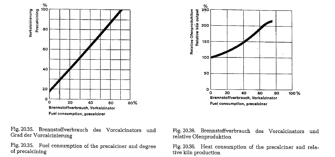
construction sizes of precalcining systems with separate precalciners. The quoted production capacity depends on variou!influential factors (e.g. kind of fuel, burnability of the _. raw mix, elevation above sea-level, ambient tempera ture, etc.), and can fluctuate within certain limits.


FLS-Integral kiln with precalcining at kiln inlet
Efforts of the F. L. Smidth Co. to reduce investment costs, combined with a simpler layout of the kiln arrangement, resulted in the development of a new precalcining process. The difference between this procedure and the process described above is that the hot kiln exit gases come together with the uncalcined raw mix, which in the upper three stages of the cyclone preheater is heated to a temperature of about 700 oc. This raw mix is led down to the kiln inlet, where it mixes with the kiln exit gases (see Fig. 20.37. and 20.38.).
When meeting the exit gases, the raw mix begins a whirling movement, thus initiating the calcining pro cess. Before the mixture of exit gas and raw mix arrives at the gas duct to the lowest preheater stage, the temperature of the exit gas decreases to about 840 o C. The kiln gases pass the kiln feeding zone, where the precalcining takes place. The raw mix, which is separated in the lowest stage of the prehea ter, enters the kiln through a specially designed feed ing pipe. This arrangement prevents the precalcined raw mix from blending with the uncalcined raw mix in the kiln feeding area. To attain a high degree of precalcination, this separation of the two raw mix lines is of great importance.
Experience has shown that when employing this pre calcining system, the temperature of the kiln gases is no longer limited to 1200 oc. Based on this know ledge, precalcining of the raw mix can be increased with increasing kiln exit gas temperature. This sys tem works with only one burner; an auxiliary firing for the precalciner is not required.
High exit gas temperatures result in larger tempera ture differences between kiln gases and kiln feed, thus allowing a shorter kiln. The ratio between the exit gas temperature at the kiln feed end, and the attained degree of precalcining is shown in Fig. 20.39.
A high rate of precalcining increases the specific cap acity of the kiln. The ratio shown in Fig. 20.40. is based on measurements resulting from test runs with this kiln system. Fig. 20.40. shows that a precalcining degree of 50-60 % results in a specific kiln capacity of 3.5 metric t/24 h · m3.
Since the total fuel is supplied through the hot kiln end, the comustion gases are passing the kiln. There fore, the kiln diameter is the same as for a 4-stage cyclone preheater. Also the gas velocity at the kiln feed end is for both kiln types practically the same. The higher gas temperature of this system is the reason that a larger part of the calcining process occurs in the kiln inlet area. Compared with a con ventional 4-stage cyclone preheater, the kiln length is considerably reduced, depending on the degree of precalcining at the kiln inlet. A shorter kiln reduces the heat losses by radiation through the kiln shell; also the power requirement for the kiln drive is cor respondingly lower.
Integral kilns with precalcining inside the kiln feed end are presently supplied by FLS up to a capacity of 4500 metric t/24 h. This kiln works in conjunction with all known types of clinker coolers.

The KHD Humboldt Wedag AG Pyroclon-pre- calciner
KHD Humboldt Wedag AG applies two types of pre calciners which are known under the designation Pyroclon “R” (regular) and Pyroclon “S” (special). The construction consists mainly of:
- One or more ducts leading from the kiln inlet to the preheater system, integrated with special combustion chambers, where combustion of fuel takes place in a composition of preheated cement raw mix which is thoroughly intermingled with hot exit gases coming from the rotary kiln; at this place the combustion serves the only purpose for calcination of the cement raw mix.
- A gas duct supplied with internal construction to generate turbulence, leading directly from the reaction route vertically upwards, and then recur rent downwards.
- A cyclone-type separator; the above described gas duct leads directly into this cyclone, from where the raw mix is fed into the rotary kiln; this cyclone is simultaneously the lowest preheater stage (see Fig. 20.42,).
The possibilities for the process to use the second burning point depend on how the necessary combus tion air is supplied to this burning point; the air can be led separately outside and along the rotary kiln (Pyroclon “R”), or inside through the rotary kiln (Pyro clon “S”). These possibilities depend on the following conditions:
Starting .from a certain production capacity, i.e. approximately 2500 t/24 h, the combustion air is led to the second burning point through a tertiary air uct outside the rotary kiln (Pyroclon “R”). At produc tion capacities below this limit, the Pyroclon “S”-pro cess can be applied.
The application of the one or the other installation depends on different circumstances:
The kiln dimensions can decrease with an increasing degree of calcination performed inside the preheater. An almost complete calcination can be attained in the preheater, if 65 % of the heat requirement is sup plied to the preheater as fuel. At the same time, the free space cross-sectional area of the rotary kiln could be reduced by 65- 70 %; this means that even at kiln capacities of up to 8000 t/24 h, the kiln diame ter would not exceed 5.6 m. However, this requires conveying of the combustion air from the clinker cooler directly to the preheater, i.e. bypassing the kiln, otherwise the gas velocity in the rotary kiln would be too high.
Such far-reaching reduction of the rotary kiln dimen sions reduces the radiation losses considerably; on the other hand, falling below a minimum kiln size, can be disadvantageous.
If e.g. a plant would be designed with a capacity of 1500 t/24 h, with 65 % of the fuel supply going into the preheater, and with a kiln diameter of 3.2 m, then it would be necessary to supply a part of the tertiary air separately to the preheater; this kind of arrange ment would show a disandvantageous thermal load in the burning zone, expressed in kcal/m2 of kiln lining.
Simultaneously, it should be noted that reducing the kiln size as described, does not result in savings on investments, since the insulated duct for tertiary air requires a high investment cost.
This example shows that below certain capacities, conveying of combustion air to the second burning point through the kiln is appropriate (Pyroclon “S”); however, in this case the gas velocities at the kiln feed end must not exceed a certain limit, to avoid heavy dust circulation between kiln and preheater.
Besides the criterion of the maximum gas velocity, it can happen that when conveying the combustion air through the rotary kiln, the excess air in the flame could reach values which should not be overstepped; this results from the experience that with an oxygen content at the kiln feed end of more than 7 %, a fast heating up of the burning zone after kiln disturbance, was not possible. The reason for this is the known fact that with increasing excess air, the flame tempera ture decreases.
As long as at regular kiln operations the secondary air temperature is at a normal level. it is possible to guarantee regular clinker burning with the resulting flame temperature, despite a high additional heating rate in the preheater, and high oxygen contents in the kiln flame.
However, if kiln upset conditions lower the heat sup ply to the cooler, which consequently decreases the secondary air temperature, then the flame tempera ture is not high enough to guarantee regular clinker burning. Therefore, when erecting new precalciners with conveying of combustion air to the second burn ing point through the kiln, Humboldt-Wedag recom mends additional heating rates only up to 30-35 % as operational and economically feasible.
Fuels used for the Pyroclon-precalciner can be solid, liquid or gaseous.
The diagram in Fig. 20.41. shows the different con struction possibilities for plants with capacities of 1000-8000 t/24 h, considering the correlations des cribed above. At the same time a heat consumption is expected, which depends on the plant size, and the amount of fuel; this heat consumption is shown in the diagram.
From Fig. 20.41. results that a m1mmum heat con sumption can ge achieved when applying a second burning point, and with plant capacities between 4000- 5000 t/24 h; under these conditions the kiln diameter (4.8-5 m), and the thermal load of the burn ing zone (4.7 x 10⁶ kcal/m2 · h) show the most favora ble figures.


Fig. 20.42. shows a kiln plant with a Pyroclon “R” pre calciner of the KHD Humboldt Wedag AG.
According to the manufacturer, the· Pyroclon R-pre calciner allows for an almost complete decarbonation of the raw mix, heating it simultaneously up to approx. 900 o C. To install for such raw mix the right burning machine to the calciner, KHD Humboldt Wedag AG applied a rotary kiln with an L: D ratio of 10: 1 (so called Pyro-rapid kiln). Rotary kilns with the quoted L: D ratio are also being built by other manu facturers as e.g. Krupp Polysius, Fuller etc.
The way of conveying the tertiary air, influences the applicability of the various clinker coolers. Thus, satellite coolers allow air conveying only through the rotary kiln (Pyroclon “S”), whereas grate, rotary, and shaft coolers can be applied for both systems.
According to KHD Humboldt Wedag AG, almost 80 Pyroclon-precalciners were until now (1984) supplied world-wide
KHD Humboldt Wedag AG manufactures Pyroclon preheaters also in special construction for cement raw mixes with high alkali chloride and alkali sulfate contents.
The KSV-precalciner of the Kawasaki Heavy Industries, Ltd., Japan
KSV is an abbreviation for “Kawasaki Spouted bed and Vortex chamber”; this precalcining process has been developed by the Kawasaki Heavy Industries, Ltd., Tokyo, Japan.
The KSV-precalciner consists of a calcining furnace installed in the lower part of a conventional suspen sion preheater (SP); this furnace is a combination of a spouted bed ·and a vortex chamber. In this process, almost the total calcination is completed in the pre heater, working in conjunction with the KSV-precal ciner. According to the manufacturer, the KSV-pro cess increases the capacity of the rotary kiln 2- 2.5 times as compared to the conventional SP. The length of the KSV-process rotary kiln is about 37% shorter than that of a conventional SP rotary kiln. Fig. 20.43. shows a schematic of this precalciner.
The spouted bed consists of an inlet throat and a cylindrical chamber, into which some of the raw mix is fed. In its upper part, where the raw mix concen trates most, it is furnished with burners. The vortex chamber is an extension of the spouted bed. The vor tex chamber has two openings; one for the inlet of the kiln exit gas, and the other for the outlet of gas and raw mix into the lowest cyclone stage of the pre heater.

The velocity of the tertiary air current in the duct (throat) is about 20-30 m/sec; entering the enlarged spouted bed, the air velocity decreases to about 5-10 m/sec, generating simultaneously a descending air current near the wall of the spouted bed; this results in a turbulence of air and raw mix particles (Fig. 20.44.). Due to this effect, the raw mix circulates in the chamber, thus forming a concentrated mixing zone in the lower part of the spouted bed, where also burners are located for calcination of the raw mix.
Part of the raw mix which is blown upwards from the spouted bed into the vortex chamber, is instantly mixed with high temperature kiln exit gases (1000-1100 oq, introduced tangentially from the rotary kiln into the lower part of the vortex chamber, where the final stage of calcination takes place. The calcined raw mix particles are carried by the gas stream to the upper part of the vortex chamber, and from here through the discharge opening into the lowest cyclone stage of the suspension preheater. For a bet ter mixing effect, tertiary air can be introduced tan gentially into the lower part of the spouted bed, as is shown in Fig. 20.45.

Kawasaki Heavy Industries supplied to the ISA-plant of the UBE Cement Company, Japan, a preheater KSV-precalciner production line, which shows the following data:
Specifications
Preheater, manufactured by Kawasaki Heavy Indus tries: Capacity


Fig. 20.46. Flow chart of a preheater working in conjunc tion with a KSV-precalciner

Fig. 20.46. shows a flow-chart of a preheater working in conjunction with a KSV-precalciner with tempera ture data of the most important process points
Fig. 20.46.a. shows a KSV precalciner and rotary kiln arrangement constructed by Kawasaki Heavy Indus tries. This plant has been built for the Amori Cement Works of the Tohoku Kaihatsu Co., Ltd., Japan.
KS-5-System of the Kawasaki Co.
A newly developed suspension preheater of lower heat and power consumption is the Kawasaki 5-stages suspension preheater (KS-5), based on the same principle as the Kawasaki KSV-precalciner pro cess.
The most innovative feature of this suspension pre heater and precalciner is the application of horizontal cyclones which are used for intermediate stages, sub stituting konventional cyclones.
According to the manufacturer the new horizontal cyclone provides less than half the pressure loss of a conventional cyclone.
Also, the unit is of compact construction, so that radiation heat loss through the cyclone casings can be reduced, compared with conventional cyclones.
The flow speed in conventional cyclones is 4- 4.5 m/s. According to the manufacturer, the speed in a horizontal cyclone can be increased two to three times of the quoted figure, and therefore the diameter of the cyclone can be approximately 70% of a verti cal cyclone, thus reducing the height of the cyclone. A horizontal cyclone is schematically shown in Fig. 20.46.b.
Kawasaki states further that the KS-5-System permits fuel savings of roughly 4 %, and that the temperature of the exhaust gases is lowered by roughly 40 a C. resulting in large savings of thermal energy. The sav ings in power consumption of the ID-fan equals 0.44 kWh/kg clinker.

In Japan the following cement manufacturers have adopted the KS-5-System:

The heat consumption of a 2400 t/d plant amounts to 725 kcal/kg clinker
Fig. 20.46.c. shows the scheme of the KS-5 precalcin ing system with horizontal (H) and vertical (V) cyclones

Precalcining aceording to the MB-process
In the course of the increasingly higher demands on the emission limits of NOx- and hydrocarbons in thermal processes, 0+K further developed the counter flow process (system Miag) predestined for this requirement of a precalcining process.
As shown in Fig. 20.47., this system consists of the vortex shaft with a fluidized bed and a tertiary air duct which is splitted into a combustion line, and the quaternary air duct.
Liquid and gaseous fuels are directly blown into the combustion line; with solid fuels the tertiary air enters the combustion line via nozzle burners.
The designation ME-process is short for Miag Buhler.
Fig. 20.48. shows that the recuperated air from the cooler and/or from the kiln hood is supplied to the vortex shaft via the tertiary air duct 2, to the combus tion line 3, and to the quaternary air duct 4. The fuel 8 is added to the tertiary air in the combustion line 3. The feeding point depends on the kind of fuel. The length of the combustion line 3 is adjusted to the combustion time of the fuel, not striving for a complete combustion. When using solid fuel, and depend ing on the resulting ash, the ash discharge 5 can be optionally led into the kiln inlet compartment, and/or into the vortex shaft 1.

In the lower part of the vortex chamber 1, the kiln gases, and the combustion gases of line 3 are mixed for after-combustion with the quaternary air of duct 4 in the upper part of the vortex chamber or reactor respectively.
The raw mix 6 is added to the hot gases of the reactor in the upper part of the reactor and/or in the connec tion pipe between reactor and the cyclone separator. Via pipe 7, the separated raw mix flows into the reac tor and enters the kiln 9.
The process described shows the following character istics:
It is known that the calcination time is much shorter than the combustion time of the precalcining fuel. For this reason the ME-process separates calcining, and combustion of the precalcining fuel, taking into account the thermodynamical, and chemical as well as mineralogical requirements. The combustion is effected directly in the tertiary air flow at a high 02 partial pressure, which leads to short combustion times and therefore to smaller construction sizes. As no mix is fed into the combustion line and therefore, no additional C02 is set free, the combustion can freely take place, whereby however, the th.ermal inducement of NOx has to be considered.
NOx-formation is avoided by burning the whole pre calcining fuel in the combustion line in sub stoichiometrical conditions, and by keeping the tem perature below the formation temperature of NOx.
The subsequent mixing with the kiln exhaust gas in the shaft with fluidized bed lowers the CO-partial pressure, so that in the after-combustion effected in the reactor by means of the quaternary air, a thermal NOx-formation is also avoided.
As the combustion is now completed, the whole ther mal energy of the secondary fuel is at disposal in the gas flow to calcine the raw mix.
This kind of process furthermore guarantees the exceeding of the cracking-temperature of the poly chlorinated hydrocarbons, thus enabling the use of low-quality fuels in precalcining processes.
From the subsequent cyclone separator the raw mix is fed in counterflow to the kiln exhaust gases in the lower part of the reactor, so that the alkali halides contained in the kiln exhaust gas are precipitated on the raw mix and therefore cannot enter the preheaterز
PASEC precalciner process
With the goai to achieve the possible lowest heat consumption, VOEST-ALPINE AG in cooperation with SKET/ZAB, developed a new style preheater system which is marketed under the registered name PASEC.
The name PASEC characterizes the peculiarity of the system, and is short for PArallel gas flow, SErial material flow Calciner. A 5-stage version, which was erected in the Mannersdorf plant of the Perlmooser Cement Co., Austria, is in operation since 1984.
The process
Fig. 20.49. shows a 5-stage cyclone preheater with rotary kiln, and grate clinker cooler. After the lowest stage 05, the kiln gas is mixed with the gas of the two calciner cyclones, and is led in two streams along the preheater. The control of the gas steam dividing is performed by a damper in the tertiary air duct, or the kiln gases can also be throttled, in extreme cases, by a slide valve after cyclone 05.

While. the gases pass evenly through the parallel arranged cyclone towers, the raw mix fed into thy 0-tower, changes the towers 0 and V, and is finally- , after separation in cyclone OS -led into the calciner. The tertiary air, which is extracted from the kiln hood, is led to the calciner as combustion air, having a temperature of 1000 oc.
Besides the already known advantages of precalciner arrangements (shorter kiln dimensions, longer refrac tory life, smooth kiln operation, etc.) this system attains, according to particulars of the VOEST ALPINE Co., a lower heat consumption of 30 kcallkg clinker, as compared to traditional precalcining pro cesses, and this because of the following reasons:
- Since actually only one half of the gas stream gets in touch with the total raw mix quantity, exit gas temperatures, and exit gas losses are considerably The explanation for this is that the ratio of the heat capacities of gas to raw mix as com pared to conventional processes is 1 : 2. Tradi tional processes work with. a ratio of only 1 : 1.
- Since in each tower a::td stage, actually the half volume of gas is being cooled by tne total raw mix, the heat capacity ratio is cut in halves. The heat capacities comprise the specific heat of the com ponents of gas and raw mix needed per kg clinker.
- By feeding the total raw mix from cyclone V4 into the riser of stage OS, the kiln gas of approximately 10SO oc is being cooled below the calciner tem perature of 800 oc.
- Compared to traditional systems, the mix temper ature of kiln and calciner gas of 830 o C is con siderably lower, which results in a reduction of exit gas
- The separate conveying of the kiln gases into the stage 05, and mixing with the exit gas from the calciner create on the one hand optimum calcin ing conditions in the calciner, which is fed only with tertiary air. On the other hand kiln exit gases containing noxious matter (alkali, chlorine) are not led through the calciner, but separately cooled below the critical temperature range, and then diluted by calciner exit gases, which are low in noxious matter.
The 5-stage PASEC-system is operated with a heat consumption of 700 kcal/kg at an exit gas temperature of 230 oc. The 4-stage version with an exit gas temperature of 280 oc needs 725 kcal/kg clinker.
Because of the described separate conveying of gases, this system qualifies especially for a conception with bypass, with the help of which kiln exit gases con taining noxious matter, can be efficiently removed by suction.
Operating results
In the Mannersdorf plant of the Perlmooser Cement Co./Austria, a 5-stage precalciner arrangement, a 4 x 60 m rotary kiln, and a grate cooler was commis sioned in August 1984. As first operating results, the following data are presented:


Precalciner
From a geometrical point of view the precalciner is a vertical cylinder with a tight orifice at half height. The lower part consists of a cone with a tangential inlet of tertiary air. 1 raw meal feed and 2 burners are installed in the area of the conical part.
Simplicity is characteristic of the design of the pre calciner and grants performance of the essential func tion, namely the flameless combustion of raw meal and fuel mix.
The tangential air inlet and the feeds for raw meal and fuel installed just above provide an intensive mix of fuel and raw meal right from the beginning of the calcining process.
The enthalpy liberated from the fuel is absorbed by the oncoming raw meal of 800 degree (0 C) directly and performs a flameless calcination at 860 degree ( C) in an atmosphere poor in C02-gas.
The orifice in the middle of the calciner effects a second mix with the result that fuel burns out homo geneously and that local superheating is avoided.
Burning out of fuel is controlled by an analyser tak ing samples from the cyclones V5. In practice the C02-concentration is zero.
In order to compensate the variations of the raw meal and fuel a governor keeps the calcining temperature at 860 degree (0 C).
Start up
Due to the fact that almost nothing is known about start up of this type of plant the following paragraph deals with it taking this brand new system as an example.
The heating up process begins with the ignition of the auxiliary burner which is installed in the tertiary air duct. After 5 to 7 hours the ignition of the kiln burner follows.
Now are two burners in operation to heat up the sys tem. The draught is adjusted in a way to enable the heat to be kept in the kiln and lower part of the pre heater.
After 15 to 17 hours from the ignition of the kiln burner the target temperatures are reached, namely approx. 1000 degree (0 C) at kiln inlet and approx. 800 degree (0 C) at cyclones of stage 5. The system now is ready to be fed with raw meal.

After nominal capacities of preheater fan, all burners and kiln drive are switched on raw meal feed starts at so%.
Increase of raw meal and production up to nominal capacity is made within 3 hours. The auxiliary burner is switched off and dismantled after the secondary and tertiary air has been heated up by the oncoming clinker.
The system becomes stabil after the secondary and tertiary air has reached a temperature of approx. 1000 degree (°C ) and adapts itself to a fuel ratio of 51 % precalciner to 49 % kiln.
All data concerning the PASEC-precalciner are from VOEST-ALPINE Co., Linz, Austria.
The DD process
The Dual Combustion and Denitration Furnace (DD) was developed by Nikon Cement Co., Ltd., in coopera tion with Kobe Steel, Ltd., Tokyo, Japan, who manu factured the DD furnace as well as the suspension preheater.
Fig. 20.51. shows a schematic diagram of a 3600 t/d DD process furnace. The DD furnace is divided into the following four zones, according to their specific functions.
1-Reducing zone (Zone I). This is the inverse coni cally shaped part of the lower side of the DD fur nace whose main function is to reduce NOx in the kiln exit Several denitration burners are pro vided along the walls of Zone I. The DD furnace gases together with the raw mix serve to reduce NOx, with the aim to convert it into harmless Nz.

2-Fuel cracking and burning zone (Zone II). This is the cylindrical part of the DD furnace, whose function is to vaporize, crack, and partially burn the fuel oil injected into this zone.
3-Main burning zone (Zone III). This is the central part of the DD furnace whose main function is to burn the fuel and to transfer the generated heat to the raw mix.
4-Burning completion zone (Zone IV). This is the top cylindrical part of the DD furnace whose main function is to burn the remaining fueL and to acce lerate calcination of the raw mix.
Because more than 60 % of the total fuel is supplied by the precalciner where it burns with a low tempera ture equal to that of the calcining temperature of the raw mix, the NOx volume of the exhaust gas of the DD furnace is considerably reduced. The NOx content in the exit gas of the 4th cyclone is quoted as 100 ppm (conversion value to 10% 02). This is low enough to meet the Japanese governmental regulation standard for air quality
The Buss-Convex-Calcination process
This system can be regarded as an alternative to the commonly known flash tube/ cyclone system for pre heating and calcining particulate solids. Heat and mass transfer takes place in vortex chambers -the so-called Convex units -where solids are rotating in form of fluidized particle rings in a centrifugal field created by the hot gas.
Due to the considerably higher product-to-air ratio in the vortex -compared to a pneumatic tube calciner which results in a corresponding higher particle residence time the product temperature at the Con vex outlet is normally close to the gas temperature. Thus relatively low exhaust gas temperatures can be achieved by a combination of some two to three Con vex units. The principal operating feature of Convex calcinators is shown in Fig. 20.52.
In the Convex the mixture of suspended solids and hot gas enters the cylindrical chamber tangentially at high velocity. Here all particles above a criticq,l size are instantaneously separated out by centrifugal forces.
In the Convex the mixture of suspended solids and hot gas enters the cylindrical chamber tangentially at high velocity. Here all particles above a criticq,l size are instantaneously separated out by centrifugal forces.
The particles form a rotating ring of solids with a velocity clearly different from the gas velocity.

Small and light particles pass the unit together with the gas rather quickly, while coarse particles are rotating considerably longer in the unit due to the classifying effect of the Convex. They leave the chamber together with the gas through a central out let as they are displaced by the newly entering material. The residence time of coarse particles in Convex units is many times longer than that of fines. This effect allows to achieve a uniform product tem perature widely independent of the particle size.
Parameters like the product-to-gas ratio -defined as kg solids per kg gas -as well as the particle size and the geometrical size of the Convex unit have an important influence on solids residence time in the unit. Depending on the diameter of the chamber one may expect- for example- 10 to 30 seconds resi dence time per Convex unit at particle sizes up to 2 mm and product – to – air ratios of approx. 0.3 kg/kg.
By installing several units in line longer residence times can be achieved easily. Thus in practical opera tion a set-up of 5 units for example allows to achieve 2 to 3 minutes mean particle residence time.
The simple design of the Convex units makes it easy to protect them against high temperature and/or wear by lining the internal surfaces. For preheating or calcination purposes combustion gases from coal-, fuel- or gas-fired burners or exhaust gases from rotary and other types of kilns are used.
A typical flow-sheet of Convex units used for calcina tion processes is shown in Fig. 20.53. This plant arrangement -in pinciple a one-stage multiple unit pseudo-counter-current flow set-up – is preferably applied, if at low exhaust gas temperatures high final product temperatures should be achieved. As the product residence time in each unit is remarkably longer than in a cyclone the exhaust gas temperature can be reduced – depending on the initial product characteristics – to 100 to 200 oc. This results in a good thermal efficiency for preheating and precalcining processes and allows to reduce the size of the subsequent kiln.
One of the essential advantages of Convex heat exchangers compared to cyclones – beside of a somewhat higher heat economy – is the reduced space requirement of preheating installations due to the compact lay-out of Convex units. Large buildings or steel structures mostly needed for cyclone/flash tube systems can thus be avoided. A Convex unit for 100,000 m3/h gas throughput for example only needs approx. 2 m diameter by about the same width. The lay-out of a multiple unit plant normally uses gravity for the product transport from inlet to outlet and a corresponding arrangement of the vortex chambers. This however is not a necessary condition for proper operation as many Convex plants are on stream where the units are installed in a horizontal set-up.

Additional precalcining processes
There exist a row of other precalcining processes, some of which are also connected with denitrification or in other words with the reduction of nitrogenoxides to non-toxic nitrogen (N2) in the exit gases. These processes are actually based on the same prin ciple, whereby only the structural systems of the pre calciners differ among themselves. In the following the design features of some precalciners are schemat ically shown, from which the process flow can be seen, and therefore, a description seems not to be necessary.
The GGprocess
The GG precalcining process which works in conjunc tion with a reduction arrangement of the NOx con tent in the exit gases, is a development of the Mitsub ishi Heavy Industries Co., Japan. According to the manufacturer, the NOx content in the exit gas can be reduced to below 100 ppm (conversion value to 10 0/o 02), which in comparison to Japanese standards is a very low figure. Fig. 20.54. shows the scheme of a GG precalciner.
The acronym of this process (GG) was formed from the designation Reduction Gas Generator.
The SCS process
The designation of the SCS process was formed from the initial letters of “Sumitomo Cross Suspension Pre-heater and Spouted Furnace”. This process was devel oped by the Sumitomo Cement Co., Ltd., Japan. Fig.20.55. shows the schematic arrangement of the SCSprecalciner.
The heat consumption of the SCS precalciner work ing in conjunction with a five stage vertical and hori zontal cyklones preheater is quoted to be 690-700 kcal/kg clinker, at an exit gas temperature of 255- 260 °C. and at a total pressure loss of 500 mm WG at the inlet of the ID-fan.
The BKM process
The BKM precalciner is a development of the Bab cock-Krauss-Maffei Co., West Germany. This precal ciner is designed for high throughputs, and can only be used in twin suspension preheaters.
Fig. 20.56. shows the schematic arrangement of a BKM precalciner, as well as the gas and material flow [259o].

Air cannons in heat exchangers against material build-up
(VSR Engineering Co., D-4330 Milhlheim-Ruhr,W-Germany)
Formation of build-up in heat exchangers can be prevented or kept low by the structural design of the systems, the way of operation and the raw material composition. As all of these measures involve consi derable costs, up to now build-ups were mostly removed with rods, air lances or by high-pressure water guns.
Since 1980, air cannons are being used for preventing the formation of material build-up. Air cannons are pressure vessels with a built-in or built-on, precon trolled quick exhaust valve which releases the stored compressed air of 6-10 bar as an air blast with sonic speed.
In or on the surface of the refractory high-tempera ture-resistant nozzles are located, which divide the air blast and guide it parallel over or against the area to be cleaned (Fig. 20.57.). The raw mix with partly melted alkalies which settles due to turbulences and in zones of insufficient flow rate, is again returned to the gas flow by the sharp, streamlined air jets before it consolidates and hardens because of heat transfer through the refractory. Thus, build-ups are actually not removed but do not occur at all if the blasts are repeated frequently enough. In most cases, a fre quence of every 10 to 15 minutes, but often also only hourly or once or twice per shift is used.

The cleaned area ranges between 2-6m2, so that, according to the problem to be solved in the indivi dual kiln zone, the following blow nozzle numbers may be applied (see Fig. 20.58.).
With proper arrangement of the air cannons and selection of the constantly further developed high temperature-resistant blow nozzles, there exist no temperature and material problems. Through central compressed-air supply and sequential actuating of the units via centrally arranged cases with solenoid valves, the control of the system is fully automatic. According to the manufacturer, the air consumption of a medium-sized system of 30 air cannons with 50 1 storage volume at 8 bar operational overpressure and a blow cycle of 15 minutes comes to approx. 2 Nm 3/ min., which can be neglected when making a kiln heat calculation.
Apart from the personnel costs saved and the health hazards avoided, operations cost savings, i.e. increases in efficiency of up to 5% are achieved, says the manufacturer.
Air cannons are also applicable for the removal of mushrooming (“snowman”) in the grate clinker cooler inlet and the ring formation in rotary kilns.
Sir,
you had supplied one kiln of size 3.8 M DIA X 60 M lg for Udayapur cement industries ltd Jaljali UDAYAPUR Nepal .
We want to upgrade the system to 1200 TPD/2500 TPD .
Can you suggest us .
its some of equipment not performing
Stacker operation
Reclaimer operation
No blending as compressor is down from many years as its spares are not available
Coal Mill VRM is running at low out put
Cement mill Inlet brg metal chips are observed and no spare set availble.
An early reply shall be highly appreciated.
Warm regards
SC Sharma
email scsharma.ucil@gmail.com
scsharma59@rediffmail.com
No GA drg available could you help us