Contents
Clinker cooling
The cooling of the clinker influences its structure, the mineralogical composition, as well as the grindability, and consequently the quality of the resulting cement.
TO DOWNLOAD THE EXCEL SHEET AND ALL THE OTHER USEFUL BOOKS AND RESOURCES KINDLY CLICK HERE

Clinker cooling is necessary because:
- Hot clinker is difficult to convey
- Hot clinker has a negative effect on the grinding Process.
- The reclaimed heat content of the hot clinker of about 200 kcal/kg, is an important factor lowering the production cost.
- Proper cooling improves the quality of the cement.
Speed of clinker cooling
The speed of clinker cooling influences the ratio between the content of crystalline and liquid phases in the clinker. During slow cooling, crystals of almost all clinker components are formed, whereas fast cool ing hampers formation of crystals, causing part of the liquid phase to solidify as glass. Moreover, fast cool ing prevents growth of crystals. The proportion of liquid phase in clinkers from rotary kilns is in the range from 20- 25 %.
Fast clinker cooling influences especially the behav ior of the magnesium oxide, and therefore also the soundness of the resulting cement. The faster the clinker cooling, the smaller the periclase crystals (magnesium oxide), which emerge by crystallization of the liquid phase.
Soundness and clinker cooling
The soundness of the hardening Portland cement depends on the size of the periclase crystals. The hydration of larger periclase crystals, which is con nected with a simultaneous increase in volume, is slower than the hydration of the clinker forming minerals; this impairs the soundness of the hardening cement. The maximum size of the periclase crystals which hardly impair the cement is about 5-8 microns. Slow clinker cooling can produce periclase crystals about 60 microns large. It was found that 4 % periclase crystals in the cement, up to 5 micron in size, show the same rate of expansion in the auto clave test, than 1 % periclase crystals, which are 30- 60 microns large.
The American ASTM Standards on Cement [261], limit the expansion of Portland cement (Types I-V) in the autoclave test to 0.8 %. Slowly cooled clinker with an MgO-content of about 2.5 %, mostly fails the autoclave expansion test. Magnesium oxide solidified to glass, does not impair the soundness of cement.
Rapid clinker cooling allows for a higher MgO-con tent in the clinker, whereas slowly cooled clinker should have a rather low MgO-content. The cooling rate of clinker with up to 1 % MgO is not so decisive for the soundness than MgO-contents between 1 % and the upper limit, which in cement standards is mostly 5 %, in the British standards 4 %.
Slow clinker cooling promotes the growth of clinker minerals. The size of alite crystals does not only influ ence the clinker”s grindability (large crystals need additional energy for comminution), but also affects hydration and cement strength. Alite crystals which by proper burning and rapid cooling are kept small, result in higher cement strengths [265]. Of two cements with identical chemical composition, the one with smaller alite crystals (15 microns), was stronger; its 28-day compressive strength was 391 kg/cm2, whereas the compressive strength test of cement with 40 micron diameter crystals was only 293 kg/cm 2 [262].
Cooling and resistance to chemical attack
Rapid clinker cooling also increases the sulfate resist ance (sodium and magnesium sulfate) of the cement. This is explained by the fact that the C3A-content, which is related to the resistance of Portland cement to attack by sulfate solutions, is mainly present in aglassy state, when cooled rapidly; in this form the C3A is much less susceptible to attack by sodium or magnesium sulfate.
Fig. 21.1. shows the expansion of two mortar rods, made from the same clinker containing 11 % C3A, and stored in a 5 % solution of magnesium sulfate. In one case- applying slow cooling- the C3A crystal lized completely, whereas in the other case the clinker was cooled rapidly [263]. The curves show the definite advantage of rapid clinker cooling.
Cooling and grindability of the clinker
By means of two diagrams, Fig. 21.2. shows a grinda bility comparison of rapidly and slowly cooled clinker. Clinker which was (slowly) cooled in a rotary cooler shows a higher specific power requirement for grinding in kWh/t, than clinker which was rapidly cooled in a Fuller grate clinker cooler [264]. A higher proportion of liquid phase, as well as smaller crystals of clinker minerals, cause the grinding of this clinker to be easier than grinding of slowly cooled clinker.

These observations concerning the necessity of rapid clinker cooling and the ensuing preheating of air were recently decisive factors for the development of clinker coolers.
Clinker coolers
To form an opinion on clinker coolers, the following criteria should be considered:
a)The thermal efficiency of a cooler designates the ratio of the heat reclaimed from the hot clinker, and utilized in the burning process, to the total heat content of the clinker leaving the kiln. The thermal efficiency (E) is expressed as:


The thermal efficiency of rotary kiln clinker coolers of all types of design is within the range of 40 to more than 80%.
b)Another criterion for judging the cooler efficiency is the temperature difference between the hot clinker entering the cooler and the hot secondary air leaving the Furthermore, the best cooler is the particular cooler which, because of its general efficiency, supplies the maximum amout of heat into the rotary kiln with the secon dary air.
C)The degree of clinker cooling is designated as the temperature of the clinker leaving the This temperature differs in the various types of coolers from 50 to 300 o C.
D)he specific energy requirement of rotary and satellite coolers is lower than that of all other clinker coolers.
E)The cooling air volume of rotary, satellite and shaft coolers is limited to the air volume, neces sary for maintaining the combustion process in the rotary However, the clinker leaving these coolers has higher temperatures.
F)The lower temperature of the clinker coming from the grate cooler is a result of the higher air vol ume used for clinker cooling. The hot surplus air is partially utilized for drying and partially dis charged into the atmosphere; this necessitates dust collection which causes additional costs.
These influencing factors hinder the evaluation of clinker coolers, since frequently an advantage on the one hand must be paid by losses on the other.
There are four types of clinker coolers:
- The cooling drum located underneath the rotary
- Cooling drums attached to the circumference of the rotary kiln’s discharge end (satellite coolers).
- The grate cooler.
- The shaft cooler.
The rotary cooler
To begin with, the first rotary kilns of the cement industry did not have any arrangement for clinker cooling. The hot clinker was dumped in an open stor age area for cooling. These types of rotary kilns were phased out in an American cement plant in California in 1964.
The rotary cooler is the oldest type of clinker cooler, constructed to work in conjunction with the rotary kiln. The rotary cooler consists of a revolving cylin der, following the rotary kiln. Rotary kilns of 60- 90 m length, are supplied with rotary coolers of 2- 5 m diameter and 20- 50 m length. The rotary kilns of the Kuybyshev cement plant (USSR) of the size 4.5 x 5 x 135 m, are supplied with rotary coolers of 5 m diameter x 15 m length. The slope of rotary coolers is in the range from 4- 7° to the horizontal; they are mostly arranged in opposition to the kiln’s slope, since they are frequently located underneath the rotary kiln. Rotary coolers are mounted on two riding rings; the girth gear and pinion drive is inde pendent of the rotary kiln’s drive. Rotary coolers are operated with revolutions in the range from 0 to 8rpm.
About 70 % of the drum’s length is refractory lined. Rotary coolers are supplied with flights for lifting and dropping the clinker to get a thorough contact with the cooling air, and thus to increase the efficiency of the cooler.
The negative pressure in the rotary kiln induces suc tion of cold air through the open end of the rotary cooler; the cooling air passes the rotary cooler in cross-current to the motion of the clinker. When entering the rotary kiln, the temperature of the cooling air is about 400-750 oc.
The clinker leaving the rotary kiln with a tempera ture of 2370-2460 °F, after passing a transition shaft,enters the rotary cooler. When leaving the rotary cooler, the temperature of the clinker is in the range of 150-300 oc.

Wet process rotary kilns with a specific heat con sumption of i600 kcal/kg of clinker, and with an excess air rate of 1.3- 1.4, require a combustion air volume of 25 st.m3/kg of clinker. At this rate more cooler air can be supplied into the rotary kiln; this improves the cooler efficiency. The efficiency of rotary clinker coolers is: 55-75 % with the dry prod uction process, and up to about 78 % with the wet production process.
The capacity of rotary coolers is 2.5- 3.5 t/m3 · 24 h of cooler volume; on the other hand, 1 ton of clinker capacity per 24 h requires a cooler volume of 0.4-0.25 m3. The LID-ratio of rotary cooler drums is 10 : 1 to 12.: 1.
Because of the scoops which cause constant lifting and scattering of the material inside the rotary cooler, the degree of filling is hardly comparable to that of the rotary kiln. For calculation of the passage time through the rotary cooler, see section 4.15. The formula quoted in this section is also applicable for calculating the retention time of material particles in rotai:y coolers.
For maximum heat transfer in rotary coolers, an air velocity at the clinker inlet end of the cooler of 3.8-4.3 m/sec should be applied.
These velocities apply to an excess air of 10 % (n = 1.1) and to a secondary air volume of 85 % of the total combustion air.
The heat losses through the shell of rotary coolers by radiation and convection are in the range of 50- 80 kcal/kg of clinker.
After the grate cooler was introduced into the cement industry, and after the comeback of the pla netary cooler, drum coolers for clinker cooling were only temporarily and not often erected. However, in the meantime, further development of the drum cooler showed advantageous operating results.

In 1972, space requirements in an Austrian cement plant demanded a 2000 t/24 h preheater kiln with a rotary cooler, located underneath the rotary kiln; the size of this cooler is 4.4 x 46 m. The discharge tem perature of the clinker is reported to be in the rangeof 160-180 oc [266c]. Supplier: KHD HumboldtWedag AG, Ki:iln, W. Germany, see Fig. 22.2. and 22.3.
Simultaneously, and as a result of economical and technological considerations, a German cement plant also decided to supply a rotary kiln of the same capa city with a rotary clinker cooler, instead of other types of coolers [266a, 266b].
Satellite coolers -original design
In 1910, the Krupp Gruson Works in Magdeburg introduced the satellite cooler into the cement indus try. Krupp called this cooler Concentra cooler or Con centra kiln respectively. In 1922 the F. L. Smidth Company followed with its satellite cooler known in the cement industry under the name of Unax-cooler
The satellite cooler consists of several, mostly 10 or 11 sheet metal cylinders arranged wreath-like along the circumference of the hot kiln end, forming an integral part of the rotary kiln. The satellite coolers revolve together with the rotary kiln, without separ-ate drive. The particular cooling tubes are refractory lined, up to about 25 0/o of their length; for better heat transfer, the remainder of the length is supplied with chains or flights. Openings in the kiln shell allow the clinker to enter the satellite coolers. Cooling occurs cross-currently. The total cooling air enters the kiln as combustion air. The motion of the clinker in the satellite coolers is mostly parallel to the motion of the clinker in the rotary kiln; however, there are also satellite coolers supplied with internal construction, capable of conveying the clinker in the opposite direction. The total weight of the 10 to 11 old type satellite coolers is supported by the roller assembly located prior to the rear end of the satellite coolers.
Because of the excessive weight of the kiln head fur nished with satellite coolers, and the resulting stress problems of the kiln’s shell, it was impossible to go beyond a certain size of the kiln or the satellite cool ers respectively. The upper limit was reached with a rotary kiln size corresponding to a capacity of 500- 700 t/24 h, and with a maximum dimension of the satellite coolers of 1.25 x 7.5 m.
Fig. 22.4. shows a longitudinal section through a satel lite cooler of a wet process rotary kiln of the size 3.6 x 3.3 x 3.6 x 150 m, with a capacity of 550 t/24 h.

As is shown, the length of the pictured satellite cooler is about 6 m; this length is not sufficient for a useful heat transfer. The LID-ratio is 6 : 1, whereas the LID-ratio of rotary coolers is in the range from 10 : 1 to 15 : 1. The efficiency of this satellite cooler is about 60- 65 %.
The satellite coolers described above belong to the original design of this type of clinker cooler. Far more than 1000 rotary kilns were constructed with satellite coolers; the F. L. Smidth Company alone manufac tured about 660 rotary kilns with old type satellite coolers.
Satellite coolers -new design
In 1965 the F. L. Smidth Co. came out with the so-called new Unax-Satellite or Planetary cooler, which represents a far-reaching improved design of the conventional satellite cooler. Planetary coolers of new design are also supplied by other well-known cement machinery manufacturers.
The substantial feature of the new Unax-satellite coler is the forward extention of the kiln tube and the formation of an additional roller assembly for the support of the extended kiln tube. Based on this design, it was possible to apply larger satellite cooler tubes, without impairing the carrying capacity of the rotary kiln shell. Of course, a thicker shell plate is applied for the additional weight of the satellite cool ers. The LID-ratio of the new satellite coolers is approximately 12:1.
The burner floor is formed by a stationary tube which projects into the roller supported lower end of the kiln shell. A rotary kiln with the dimensions 6.3 x 5.5 x 178 m has a 35 m long stationary burner floor tube with a diameter of 4.5 m.
Fig. 22.5. shows the longitudinal section of a rotary kiln”s lower end with the new satellite cooler. Up to the present time, the new satellite cooler was applied to rotary kilns with a capacity of up to 4000 t/24 h; for this size of kiln, the size of the satellite cooler tubes is 2.4 m dia. x 29 m long.

Fig. 22.6. shows an access tunnel to the burner plat form of a kiln supplied with satellite coolers. Inside the tunnel, the hot kiln end is closed by a fire shield, which is suspended on two rollers and rails. For heat protection, the fire shield is lined with refractory. A counter-weight device keeps the fire shield pressed against a sealing around the kiln opening. The fire shield is provided with an opening for the burner pipe, and observation ports. A hinged access door is located at the periphery of the fire shield.
Fig. 22.7. shows the clinker inflow funnels into satel lite coolers arranged around the kiln”s circumference. Presently (1984) the F. L. Smidth Co. supplies satellite coolers up to a diameter of 2.55 m, and 29 m length.


Fig. 22.8. shows the total arrangement of a clinker burning plant consisting of a twin type cyclone raw mix preheater, rotary kiln with planetary coolers of new design, and the access tunnel of the burner plat form.
Cooler volume and kiln capacity
The diagram in Fig. 22.9. shows the required total usa ble volume of the satellite coolers versus the daily capacity of the rotary kilns. The 4000 t/24 h rotary kiln for example has a usable planetary cooler vol ume of 1340 m3; the specific cooler volume per metric ton capacity and 24 hours is 0.34 m3.

Rotary kiln diameter and satellite coolers
Fig. 22.10. shows the diameter of the rotary kiln ver sus the diameter of the related satellite coolers.
The new cooler tubes are lined with refractory along half the length. This is made possible, since almost no weight limitations are necessary as with the old type cooler. Thus, heat losses through the cooler walls are reduced by approximately 30 to 40 kcal/kg
Lifters in satellite coolers
For a better heat transfer, the interior of the cooler tubes is equipped with refractory lifters and lifter bars, and, above all, with internal construction con sisting of heat resistant steel and steel casting, to expose the hot clinker to the cooling air.
Fig. 22.11. shows a longitudinal section of the new Unax-cooler and three related cross-sections; as the picture shows, various lifter elements are applied for the purpose of lifting the clinker in the cooler tubes [269]. The retention time of the clinker in the cooler tubes lasts approximately 45 minutes. When entering the satellite coolers, the temperature of the clinker is in the range of 1100-1350 °C; when leaving the satellite coolers of a dry process kiln, the tempera ture of the clinker is about 120-200 o C. Here it should be noticed that cooling of the clinker is performed only with such an air volume which equals the quantity of the secondary air, which makes. 0.8-1.0 st.m3/kg of clinker and at a specific heat consump tion of 750 kcal/kg. A grate clinker cooler operated with this air volume would yield clinker exit temper atures of 250-300 o C. To this it should be added that the planetary cooler loses about 25 % of the clinker heat by radiation through the shell. In contrast to this, heat losses by radiation through the shell of the grate cooler are almost nil; this allows the utilization of the grate cooler’s waste air. In the wet production process with a specific heat consumption of 1400 kcal/kg of clinker, the volume of the secondary air amounts from 1.3-1.5 st.m3/kg of clinker. The temperature of the secondary air leaving the satellite coolers and entering the kiln, is in the dry process kiln 840- 850 o C. and in the wet process kiln 600-650 oc. To cool the clinker in the satellite coolersfrom 1350 oc down to 1000 oc takes not quite ten minutes, which equals almost the cooling time in the grate cooler. In accordance with this, a large number of comparative measuremens on clinker from plane tary coolers and from grate coolers have shown that there is no detectable distinction in the quality of clinker from the two different cooler types. Consider ing from the viewpoint of clinker quality and kiln operations, it is also presumable that cooling of clinker which occurs already in the kiln tube, can be expedient [269a, 269b]. Since the satellite cooler is operated without cooler excess air, no cooler dust collector is necessary.

Fig. 22.11. Longitudinal section through the new Unax cooler with the particular cross-sections
Heat balance of satellite coolers
Table 22.1. contains data and heat balances of satellite coolers [270]. In this table it should be particularly noticed that the heat losses by radiation through the cooler’s shell, amount to about 26-27 % of the heat input into the cooler.
Fig. 22.12. shows a heat balance diagram of an F. L.Smidth Unax-satellite cooler; this heat balance is expressed in kcal/kg clinker, and 0 ac starting temperature. The heat content of the cooling air is included.
Section 22.5.2. contains for comparison a heat balance diagram of a grate cooler (F. L. Smidth Folax cooler). In both cases it was assumed that the heat content of the clinker in the burning zone amounts to 400 kcal/ kg clinker, or 720 Btu/lb. It was further established that in both cases, the distance from the burning zone to the cooler inlet (i.e. the length of the kiln’s cooling zone) is the same. Therefore, the heat balances of both kinds of coolers are perfectly comparable with one another.


Satellite cooler drive and power requirement
The satellite cooler increases the power requirement of the kiln and of the ID-fan.
The additional power requirement for the kiln can be determined with the following formula:

Small kilns show an increase in the power require ment of about 0.3 kWh/t of clinker; the 4000 t/24 h kiln with a satellite cooler length of 27 m, has an additional specific power requirement of 27 x 0.03 =0.8 kWh/t of clinker. The pressure drop through the satellite cooler which amounts from 20- 40 mm W.G., increases the specific power requirement of the ID-fan by 0.3 kWh/t of clinker in the dry process kiln, and by 0.5 kWh/t in the wet process kiln. The total specific power requirement of the new satellite cooler is within the limits of 0.6- 1.3 kWh/t of clinker.
Cement machinery building firms which manufac tured conventional satellite coolers now also engage in construction and sale of rotary kilns with satellite coolers of the new design.
Here it should be mentioned that the following diffi culties were sometimes encountered with the new type, large satellite coolers [270a]:
- Static and mechanical overstress of the kiln shell, which resulted in cracks between the clinker dis charge openings [270b].
- Imperfect formation of the transition sockets from the kiln to the cooler tubes, which caused spillage of the clinker into the kiln and on the burner nozzle.
- Short-term durability of the refractory lining.
- Increased wear of the cooler tubes due to their thermal overstrain, as well as short-term durabil ity of refractory, metal linings and lifters; air and water cooling are applied as a makeshift.
- The problem of attaching the long cooler tubes to the kiln shell in conjunction with their thermal expansion required special constructional arrangement.
- Excessive noise pollution requires costly silen cers, such as sound-barriers on both sides of the cooler tubes.
If should be further noted that the investment cost of a rotary kiln with satellite coolers of the new design, equals that of a rotary kiln with a grate cooler included.
To compare the investment costs of both kiln sys tems, it is of importance to know the limitations con cerning the discharge of particulate matter of the cooler exit air into the atmosphere. This again depends on the local environmental regulations. In addition to the above considerations, to run a plane tary cooler it is important to know the local noise pol lution restrictions and the cost to comply with them.
Water cooling in satellite cooler
During peak loads and in case of kiln upset condi tions, high temperatures of clinker leaving the satel lite cooler, can occur. For this purpose, the F. L Smidth Co. developed an internal water cooling sys tem of the clinker, working directly ahead of the cooler outlet (see Fig. 22.13.).

Addition of cooling water is expressed in percent of clinker weight. At a cooling ability of 25 °C/1 % of water, the evaporation capacity of the water is almost completely utilized. In case of need, up to 4 % of water are continuously supplied into the satellite coolers. The above shown arrangement indicates the way how the water is supplied into the cooler.
According to the manufacturer, no caking occurs at this kind of cooling; also the heat consumption is not appreciably affected.
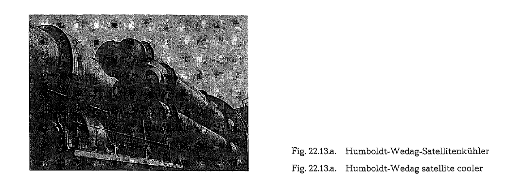
The Humboldt- Wedag satellite cooler
The Humboldt double stream cooler which in the past was in use to cool clinker from wet process rotary kilns, was replaced by the Humboldt-Wedag satellite cooler; this cooler, which is shown in Fig. 22.13.a, is manufactured by the KHD Humboldt Wedag AG for clinker capacities up to 5000 t/24 h.
The satellites consist of a transition piece, a double divided inlet elbow, satellite tube shell with internal constructions, fixed and loose supports, and of the discharge arrangement.
The refractory lined transition sections consist of high temperature resistant cast steel; this steel is in all temperature ranges free of embrittlement, and protects the sockets of the kiln’s discharge openings against wear.
The inlet elbows are exchangeable and are fastened to the satellite tube by a clamp flange, secured against turning. Their construction does not allow the clinker to return into the kiln. The inlet elbow is fur nished with a high temperature and wear resistant lining. A packing box gasket located between kiln and inlet elbow absorbs the axial heat expansions and conractions of the inlet elbow.
The satellite tubes are double supported. The fixed support arranged close to the inlet elbow, takes care for the axial fixing, and prevents at the same time dis tortion of the satellite tube. The loose support ena bles without obstruction to absorb changes of the tube length, caused by temperature variations. The required clearance between support and satellite tube is adjustable according to the demand.
Corresponding to the decreasing clinker tempera tures from the inlet elbow to the discharge opening, the satellite tube is divided into different refractory lining zones, as well as in zones furnished with special internal constructions.
The discharge opening of the satellite cooler is sup plied with a special arrangement, allowing a size clas sification of the clinker. Fine particles up to about25 mm in size, pass the exchangeable grate and are led to the clinker conveyor. Coarse clinker is dis charged through a side opening, and is conveyed through a chute to the clinker breaker.
Krupp Polysius-Drum/Planetary Cooler Com bination
To make use of the advantages of the planetary cooler (large radiation area) and to avoid the disad vantages of the drum (large dimensions), Krupp Poly sius developed a drum/planetary combination for large kiln capacities. Fig. 22.13.b. shows the arrange ment and the dimensions of an erected plant for 5000tpd.

Due to the downstream installation of the cooler combination, i.e. after the kiln, it is possible to adjust inclination and speed to the kiln capacity.
The grate cooler
The clinker grate cooler with air quenching effect, which is generally known as the Fuller-cooler, was developed by the Fuller Company in Bethlehem, Pa., to be operated in conjunction with the rotary kiln. Operation of the first Fuller cooler started in August 1937 in the Valley Forge Cement Plant in Valley Forge, Pennsylvania; this cooler was developed to eli minate the detrimental effect of cement expansion which was caused by recrystallization of the magne sia.
The Fuller grate cooler
When developing the Fuller cooler, the main object was the improvement of the cement’s quality, result ing from rapid cooling of the clinker. Simultaneously it was found that this cooler promotes a very good heat exchange between the hot clinker and the cool ing air.
The self-contained construction of the Fuller cooler provides the means to keep the cooler area clean. Compared to the rotary cooler, the Fuller cooler as such requires about 20 % less space. The Fuller cooler enables complete control of the secondary air and the clinker temperature. The heat losses of this cooler by radiation and convection are extemely low. The Fuller cooler develops a fast initial cooling of the clinker; this fact is of great importance for the forma tion of tricalcium silicate. This cooler allows for clinker input temperatures of about 1360- 1400 o C, which increases the thermal efficiency up to 72- 75 %. The application of excess cooling air results in cooling of the clinker down to 65 °C; this tempera ture allows an immediate grinding of the clinker to finished cement.
In contrast to the rotary and planetary coolers where cooling of clinker is predominantly performed by transverse air current, the Fuller cooler, cools with a combination of cross-current and counter-current air.
Presently, Fuller coolers are manufactured in sizes up to 10,000 metric t/24 h.
Originally, the Fuller cooler was constructed with 15 o slope, modelled on the Seyboth grate for boiler firing. To reduce headroom the slope of the grate was first lowered to 10 o, and later to 5 o; at the end of this trend the horizontal grate cooler was finally devel oped.
The reciprocating grate cooler consists of alternating rows of immobile and mobile grates. The grates are driven by variable speed motors; the number of grate strokes varies from a minimum of 4 to a maximum of 22/min. The size of the grate plates is 300 x 410 mm. The thrust length of the mobile grates is 120 rom. The undersize clinker particles passing the grate plates enter the air compartments, from where they are dis charged by motor operated airtight double tipping valves; in most cooler constructions usually a drag chain is applied to remove the spillage from the cooler housing. The cold grate end discharges the clinker to an inclined grid, from where the main part of the clinker, after passing the grid, drops to the clinker conveyor. A clinker breaker located at the end of the inclined grid serves the purpose of disinte grating larger chunks of clinker; it projects the clinker back to the end grates for further cooling and size reduction.
With the progressive increase in size of rotary kilns, the horizontal Fuller cooler encountered new prob lems. It happened that larger rotary kilns with capaci ties of 1000 mt/24 h and more, had a tendency to produce clinker of finer particle sizes. The hot bed of fine clinker on the horizontal grate became fluidized from the rapid expansion of the upcoming cooling air in such a way that the horizontal grates would reci procate without advancing the clinker through the hot zone, thus causing a dangerous height of the clinker bed.
The Fuller combination cooler
To overcome situations of this type the Fuller combi nation cooler was developed, the first of which was installed in 196S in the cement plant of the Atlantic Cement Company in Ravena, New York.
The first section fo the feed end of the Fuller combi nation cooler is constructed on a so slope. Simulta neously, the height of the pushing face of the grate was increased from S to 8.3 em. These provisions helped to overcome the fluid bed effect [271]. The remainder of the cooler length consists of a horizon tal reciprocating grate. Both grates have separate speed controlled drives. In further persuance of this concept, a combination cooler with three reciprocat ing grates was designed. The slope of the first two grates is 3°, the third grate is horizontal. This combi nation cooler is of a special construction that allows for numerous hot air takeoffs, i.e. flash furnace, raw material dryers, coal mills, burners, waste heat boil ers, etc.

In connection with the definition “center exit air” of the cooler, reference is made to Fig. 22.14.; this sketch shows the different kinds of clinker cooler air. The duotherm-air or duotherm circuit is explained in sec tion 22.4.3.
An alternate construction of a Fuller combination cooler consists of:
- a sloping grate
- a short horizontal grate
- a clinker breaker
- a long horizontal grate.
The advantage of this arrangement is that after crush ing the large clinker chunks, the material is then cooled to the required temperature.
Together with the introduction of the preheater kilns with their low heat consumption for clinker burning, there was a growing increase in the demands pertain ing to the heat economy of the grate cooler. Now it was imperative to introduce more heat into the rotary kiln With a lower volume of secondary air. For this purpose the height of the clinker bed was increased up to 4SO- 760 mm, thus producing a higher temperature of the secondary air. This was achieved by narrowing the width of the inclined grate as well as by lowering the grate speed. The grate width at the clinker feed end equals approximately half the kiln diameter measured on the refractory.
The horizontal grate is 60- 90 em wider than the inclined grate, with higher grate velocities and a thin ner clinker bed for lower pessure of the cooling air.
Fig. 22.15. shows the longitudinal section and the lay out of a Fuller combination cooler with 7 air compart ments.

Fig. 22.15. Fuller combination and reciprocating grate cooler; view of both sides
Underneath the cooler grates, the length of the cooler is divided into individual air compartments; each air compartment is equipped with its own air fan.
A Fuller cooler with a capacity of 2000 mt/24 h is equipped with 7 air compartments. The partitions are installed from the floor up to the grate, and are sealed on the stationary grate supports. The purpose of the air compartments is, to let the cooling air flow only upward through the bed of material in the desired bed area. Thus, along the cooler length the clinker bed is divided into 7 fields of different temperatures. The expansion and the velocity of the cooling air decreases with the declining temperature of the clinker bed; concurrently with this, the required air pressure for penetration of the clinker bed drops pro portionately. Counting from the clinker inlet (the static pressure of the fan for the first air compartment is 600- 760 mm W.G.), each following air chamber is supplied with a fan of lower static pressure. The fan of the coldest section has a static pressure of 200- 250mmW.G.

The diagram in Fig. 22.16. shows material tempera tures and undergrate pressures for a typical combina tion clinker cooler, producing about 1700 mt/24 h of clinker from 1360 oc initial temperature to 65 oc discharge temperature.
To calculate the temperature of the secondary air the following empirical formula can be used:

The cooler’s clinker inlet cross-section is sized for a velocity of the ascending secondary air of 4 m/sec.
The capacity of the cooler fans is designed for a spe cific air volume of 3-3.15 st.m3/kg of clinker.
The specific grate capacity is 38- 43 metric t of clinker per 1 m2 • 24 h.
The installed power of a grate cooler with a capacity of 2000 t/24 h, including the drive for the cooling air fans, the reciprocating grates, and the vent air fans, is 1050 HP; from this amount, 700 HP is apportioned to the cooling air fans with the grate drives, and 350 HP is for the drive of the vent air fans.
This consumption can be drastically reduced by designing coolers with higher clinker discharge tem perature. Power consumption can also be reduced with the utilization of variable speed drive fans.
Since the cooling air as well as the velocity of the reciprocating grate can be controlled independently of the operation of the rotary kiln, the grate cooler is able to temporarily accept throughput fluctuations ranging up to 50 % above the normal capacity. This is considered to be routine overload.
Duotherm circuit
At the duotherm circuit of the grate cooler, part of the hot cooler excess air is led back as recirculating air into the first and second air compartments. This reduces the cooler excess air and thus the heat losses by about 25 kcal/kg of clinker, improving the cooler’s efficiency. At the duotherm circuit the consumption of fresh air can be reduced to 1.3-1.8 st.m3/kg of clinker. This procedure however, results in a higher thermal load of the grate plates. This alternate is becoming more acceptable with the advent of heat exchangers for protection and the demand for fewer plant dust emission points.
Where allowable, multicyclones are applied to clean the cooler’s excess air. Mostly however, the cooler’s dust is recovered in fabric filters, gravel bed filters or electric precipitators. The dust load before entering the filter is 10-15 g/st.m3; the dust load after leaving an electric precipitator is 0.115 g/st.m3.
Size designation of Fuller coolers
The designation of a Fuller cooler e.g. 831/1050 means that the sloping section is 8ft wide and 31ft long; the horizontal section is 10ft wide and 50ft long. A Fuller cooler with a capacity of 4000 t/24 h, with a clinker discharge temperature of 65 o C. has a size designation of 1028S/1032S/12/36H, consisting of 10 air compartments. S stands for 3 o slope, and His the designation of the horizontal grate. The length of this cooler is 96 ft or 29 m. Higher clinker discharge temperatures require shorter coolers which lower the investment costs.
Heat balance of a Fuller cooler
Table 22.2. contains the heat balance of a Fuller grate cooler of the size 825/1050; the rotary kiln is a cyclone preheater kiln. The rotary kiln’s throughput is 1934 t/24 h


Cooler efficiency
The efficiency of the cooler calculated in the table is a result of the relatively low volume of secondary air, as well as of the center exit air and the cooler excess air. If the center exit air in the production process is utilized for raw material drying, then this position can be counted as a heat input; in this case the cooler efficiency would be 85.6 %. In connection with this, it should be considered that a low specific heat con sumption for clinker burning (in the table 750 kcal/ kg), requires less combustion air and therefore the kiln consumes less secondary air, if the volume of the excess air is kept constant. In this case the calcula tion results in an apparent lower cooler efficiency. Ifthe kiln would require 850 or 950 kcal/kg of clinker, more hot secondary air would be transferred from the cooler into the kiln; this would, of course, increase the cooler’s efficiency. Since the thermal efficiency of the cooler is expressed by the ratio resulting from the heat content of the clinker and the recovered heat, the cooler center exit air used for drying, is also a position of heat recovery, which should be consid ered when calculating the thermal efficiency of the cooler.
Other clinker grate coolers
Almost all firms producing cement machinery, now manufacture clinker grate coolers or clinker coolers similar to grate coolers. These are: the Folax grate cooler of the F. L. Smidth Company, the Recupol cooler of the Polysius Company with revolving grate belt; the Krupp Polysius grate cooler; the Humboldt Wedag grate cooler, and the vibratory cooler of the Allis-Chalmers Co., USA
In the Comecon-countries, grate coolers are manufac tured: in the USSR by the UZTM-Machinery Works, in the German Democratic Republic by the VEB Cement Machinery Manufacturers in Dessau, a subsi diary of the Heavy Machinery Construction Trust Ernst Thalmann in Magdeburg. Grate coolers are also manufactured by the Pi’erov Machinery Works in Czechoslovakia. The Polish Cement Machinery Works PZBM-“Makrum” in Bydgoszcz manufactures grate coolers model “Wolga” based on a Soviet license.

The grate cooler of the Claudius Peters Company, Hamburg, W. Germany, has been manufactured under Fuller license up to 1973. The Peters-cooler (also called Combicooler) is constructed with slope of 3o, as shown in Fig. 22.18. The cooler can also be con structed with a continuous of 3°, or continuously hor izontal with no inclination at all.
KHD Humboldt Wedag AG manufactures inclined grate coolers with a continuous slope of 5 %, accord ing to the functional principle of the thrust grating with one or more thrust grates arranged successively, or also as step coolers with intermediate comminu tion of the clinker.
The inclined grate cooler shown in Fig. 22.17., cools the clinker from e. g. 1350 oc down to about 65 oc above ambient temperature. For heat recuperation, the heated cooling air is utilized by the burning pro cess as secondary air. According to the plant require ments, e. g. of the Pyroclon-process, one part of the secondary air can be led through a duct as tertiary air directly to the preheater. The excess hot air can be utilized for drying of the raw material.
To increase the temperature level of this hot air, the circulating air process can be applied, which is parti cularly recommended for the step cooler.

The remammg air is discharged to the atmosphere after passing a dust collector.
The heat recovery is achieved in the first part of the grate surface of the recuperation zone. This is accom plished by a high, uniformly distributed, slow travell ing and revolving clinker bed, as well as by the cool ing air volume, which is required as secondary air for the burning process.
The low final clinker temperature is achieved by the application of an appropriate air volume, as well as by a lower height of the clinker bed in the second part (cooling zone).
The control arrangement continuously regulates the height of the clinker bed, the travelling velocity of the grate, the air supply to the particular compart ments, and in extreme situations, also the rotary kiln’s revolutions.
The clinker leaving the rotary kiln falls directly to the grate system, located in the lower part of the cooler housing. The conveying of the clinker is per formed by the grate system, as described in chapter22.4.1. Since the travelling direction of the thrust frame deviates from the angle of the direction of tran sportation, the clinker acquires a revolving motion(relative movement). This results in an intensive heat exchange with the air.
The material quality of the grate plates is graded according to the thermal and mechanical stress. The grate plates of the recuperation zone consist of a special CrNi-steel casting; the grates of the cooling zone are CrNi-cast steel products, and those of the after cooling zone consist of Cr-steel casting.
For special requirements, KHD Humboldt Wedag AG supplies various patented types of grate plates.
Through a coupling with overload protection, the thrust frame is driven by a variable speed motor over a hollow shaft gear unit. This gear unit is manufac tured as an oscillating drive, i. e. the drive motor is mounted directly on top of the gear. A load transmis sion connects the hollow shaft of the gear with the drive shaft. Both eccentric drives are located on the drive shaft, thereby connecting the gear with the thrust frame. The frequency of the thrust is adjustable by a variable speed controller.
To compensate the coefficient of fluctuation, gener ated by the non-horizontal direction of motion of the thrust frame, shock absorbers are installed between the thrust frame and the lower housing part.
Through a grease distributor, the central lubricating device, lubricates all grate cooler bearings, the drag chain, and the clinker breaker.
The upper part of the housing is appropriately fur nished with the necessary, large sized openings for the particular air streams, to keep the dust content of these air streams low. For access to the grates, the upper housing is supplied with several doors. The lin ing of the upper housing consists of the side walls and of a simple arched roof. In the area of the mate rial bed, the side walls are furnished with high wear resistant fire clay bricks. Furthermore, a stretching device is installed for adjusting the tension of the arched roof. The refractory is protected by a baffle plate with a heavy chain curtain from the larger clinker chunks reflected by the clinker breaker. To reduce radiation losses, insulation is applied.
For removal of fine clinker particles passing the grate plates, two drag chain conveyors are directly installed in the lower part of the housing. This results in a reduced construction height of the cooler and simplifies simultaneously the cooler’s control arrangement.
The cooling air fans are equipped with: dynamic bal anced rotors, guide vanes for adjustment of the required air volumes, and with a calibrating nozzle.
Behind the grate system a grizzly is located to separ ate the fine clinker, so that the clinker breaker is fed only with coarse material.
The working width of the breaker is the same as the total width of the grate system. This guarantees an even feeding of the clinker breaker.
The control arrangement depends on the process requirements; the dust collection system must com ply with the local environmental protection require ments, and/or with the customer’s specifications.
The Polysius Recupol cooler
Polysius developed a grate clinker cooler (Recupol cooler), making use of the structural elements of the Lepol grate; the Recupol cooler is shown in Fig. 22.19.,22.20. and 22.21.
The clinker falls upon a chute, which is covered by a water cooled steel plate. The function of the cooled chute is to prevent depositing of hot clinker, i. e. the formation of the so-called snowman. For an even dis tribution of the clinker, the slope of the plate is adjustable in two directions: horizontally as well as laterally to the cooler.
During the cooling process, the clinker rests upon the travelling grate plates. After dropping the clinker at the discharge end, the grate plates are cooled on the return route, and are only transiently exposed to the hot clinker in the area of the cooler inlet.
A clinker breaker covering the total width of the cooler grate, crushes larger pieces of clinker and returns them back into the cooler for aftercooling. A chain curtain protects the refractory lining.
The number of revolutions of the cooler drive shaft is variable.
The cooling of the clinker is performed in two zones. In the precooling area, air injecting and pulsating nozzles transform the clinker layer into a state simi lar to a fluid bed, thus improving the cooling effect. This also results in an even distribution of the clinker over the width of the grate.
Due to lower aeration pressure in the secondary cool ing area, the clinker bed calms down, causing an accumulation of fine clinker particles in the upper part, and of coarse clinker in the lower part of the clinker bed. This particle separation is considered of particular advantage for secondary cooling.
The flow chart of a Recupol cooler working in con junction with a 3630 short t/24 h capacity Lepol kiln is shown in Fig. 22.21.
Waste air in the amount of 1.5 st.m3/kg of clinker is branched off from the low cooling area of the cooler, and -after cleaning in cyclones -led via pulsating blowers, back into cooler compartments No 1 and 2. Two fans, one on each side of the cooler, supply the remaining 10 compartments with fresh air. About 1.0 st.m3/kg clinker with a temperature of 290 oc, the so-called center exit air, is led into the predrying compartment of the Lepol-grate.


At a capacity of 3630 short t/24 h, the aerated area of the Recupol cooler is charged with 39.4 t/24 h · m2
The thickness of the clinker bed on the cooling grate is approximately 200 mm. In the precooling area, the pressure of the cooling air is about 350 mm W.G. In the low cooling area, the pressure drops down to about 150 mm W.G.


The FL. Smidth Folax-grate cooler
The first Folax-cooler was supplied in 1947; since that time this cooler has been greatly improved with regard to components, size, and the cooling process.
The Folax-grate cooler is manufactured for capacities up to 10,000 metric t/24 h.
The cooler is provided with separate quenching grates and blowers. The quenching grate is followed by a 3o inclined grate; then again follows a horizontal grate. As an alternative the first grate can be supplied as a horizontal grate, which is standard for larger coolers. This arrangement in conjunction with the 85 mm high pushing faces of the grates, help to over come the fluid bed effect of the clinker. Any follow ing horizontal grates are placed 600 mm lower for each subsequent stage; see (5) on Fig. 22.22. If neces sary, the cooler can be equipped in stage (5) with a clinker breaker, in front of the final horizontal grate.
A high economical dry process kiln with a heat con sumption of 750 kcal/kg is supplied with secondary air from the air quenching and from the first grate blowers. It is also possible to divide the secondary air between the kiln and a precalciner arrangement (6). The surplus air is extracted at (7) and can be condi tioned by water (8) before cleaning in an electric pre cipitator. The extraction of hot air for other purposes can be effected at point (6).
The Folax grate cooler is designed for a throughput of 30-32 t/m2 · 24 h; when working in conjunction with a large flash calciner, the specific capacity of the cooler amounts up to 40 t/m2 · 24 h.


The amount of air normally required for cooling from 1350 acto 60 ac above ambient temperature is in the range of 2.4- 2.8 stan.m3/kg of clinker. To ensure maximum operational reliability and to cope with kiln upset conditions, the coolers are designed for a blower capacity of 3.4-3.8 stan.m3/kg of clinker. For the air quenching and inclined grate section, the blowers are designed for a pressure in the range of 750-600 mm W.G. After-cooling on the horizontal grates is carried out with blower pressures in the range of 550- 260 mm W.G. Large coolers working in conjunction with flash calciners, require in the quenching and first grate section, air pressures 1000-800 mm W.G.
The capacity of the cooler shown in Fig. 22.22. is 2200 shtons/24 h; it is supplied with one inclined and two horizontal grates. The effective length is 22 m. The inclined grate is 2.4 m wide, and the throughput capa city is 833 t/m · 24 h; the thickness of the clinker bed is approximately 500-600 mm. The width of the hori zontal grates is 3.2 m.
Large size coolers with five horizontal grates show a specific throughput capacity of 2000 t/m width · 24 h. The thickness of the clinker bed is increased to 600- 1000 mm.
The particular compartments of the cooler housing are supplied with collecting hoppers for spillage; this material is released through discharge valves (10) into a drag chain trough {11). Oversize clinker particles are comminuted in a clinker breaker (12), and returned to the grate for after-cooling. The cooler insulation is protected by a chain curtain (13).
All grate plates (14) are identical in design, but their heat resistance is different. The thrust length of the mobile grates is approximately 125 mm.
To avoid the problematic sliding seals, used in trans mitting the motion of the mobile grates through the cooler shell, a special type of membrane has been developed, which absorbs the motion through defor mation. Mechanical or hydraulic drive for the mova ble frames is applied.
The conveying capacity of the grates is 100-300% higher than the nominal requirement. This, together with the overcapacity in cooling air, enables the cooler to overcome all kiln upset conditions.
As in all grate coolers, the cooling efficiency of the Folax cooler depends on the kiln’s heat consumption; thus e.g. when working in conjunction with a prehea ter kiln, a cooling efficiency of 65- 70 % is quoted

Fig. 22.23. shows a heat balance diagram of a Folax grate clinker cooler; this heat balance is expressed in kcal/kg clinker, and 0 o C starting temperature. The heat content of the cooling air is included in the bal ance.
Section 22.3.4. contains for comparison a heat balance diagram of a satellite cooler (F. L. Smidth Unax cooler). In both cases it was assumed that the heat content of the clinker in the burning zone amounts to 400 kcal/kg clinker. It was further established that in both cases, the distance from the burning zone to the cooler inlet {i.e. the length of the kiln’s cooling zone) is the same. Therefore, the heat balances of both kinds of coolers are perfectly comparable with one another.

Peters Combi stage cooler
One of the latest constructions of the grate cooler is shown in Fig. 22.24.
This design incorporates an air-cooled clinker breaker, located between the last two grates. The intermediate size reduction, comminuting the clinker particles to approximately equal size, results in a more intensive final clinker cooling on the last grate. Coolers of this design have already been supplied, and are in service worldwide since 1969.
The Peters g-cooler
The stringent air pollution standards and the result ing requirements for the installation of costly dust collectors, led to the development of a combined sys tem, comprising a grate cooler and an indirect after cooler; this system has been developed by the Clau dius Peters Company, Hamburg, W. Germany. The grate cooler is designed to supply the necessary secondary air for the kiln and has no further dust col lection facilities.

The clinker leaving the grate cooler, or the so-called recuperator, shows a temperature of 400 oc. Then an air cooled clinker breaker crushes the particles to a size< 35 mm.
A bucket apron conveyor feeds the clinker into the Peters g-cooler, cooling the clinker indirectly, i.e. absolutely dustfree, to below 100 oc.
This type of arrangement as shown in Fig. 22.25., and similar ones are in service since 1972.
The g-cooler is continuously maintained full of clinker which drops at a low speed along the lentil shaped cooling tubes. There is never any contact between the clinker and the air passing through the cooling tubes. The pressure drop in the cooling tubes ranges between 80- 240 mm W.G., depending on the particular design and the desired temperature drop.
The specific power requirement of the combined recuperator g-cooler is approximately 5-7 kWh/t clinker.
Of course, the g-cooler can also be used as an after cooler, working in conjunction with other kiln or cooler systems. Basically, the transfer points of this system are connected with dust collectors.
The grate system of IKN
A new grate system of IKN. 3057 Neustadt, West Ger many, provides horizontal air jets. The grates are permeable by air but not by clinker. For Fuller-Type coolers, the grate beams serve as air compartments.
Based on the IKN-grate-system, clinker distribution is achieved by means of slopes aerated with pulsed air.


The absolute control of the grate and bed tempera ture has led to the design of a grate cooler with drag chain conveying
The shaft cooler
The idea of cooling the clinker in a shaft cooler is not a new one. The diminishing numbers of existing cement shaft kilns represents a combination of a burning apparatus and a clinker cooler in one pro cessing unit. Numerous patents exist in the field of shaft clinker coolers.
The shaft clinker cooler developed by E Bade, is manufactured with capacities up to 3000 metric t/24 h, by the Walther-Beratherm Company in Koln Dellbriick
Since a fluidized bed creates the most useful heat transfer conditions, Bade exploited the concept to combine the counter-current cooling process in the shaft cooler with a fluidized bed.
However, in reality, the requirements of the fluid bed do not always materialize without some reservations, since such physical conditions as: equal particle size of clinker, constant quantity of clinker, and uniform air distribution, are not always attainable.
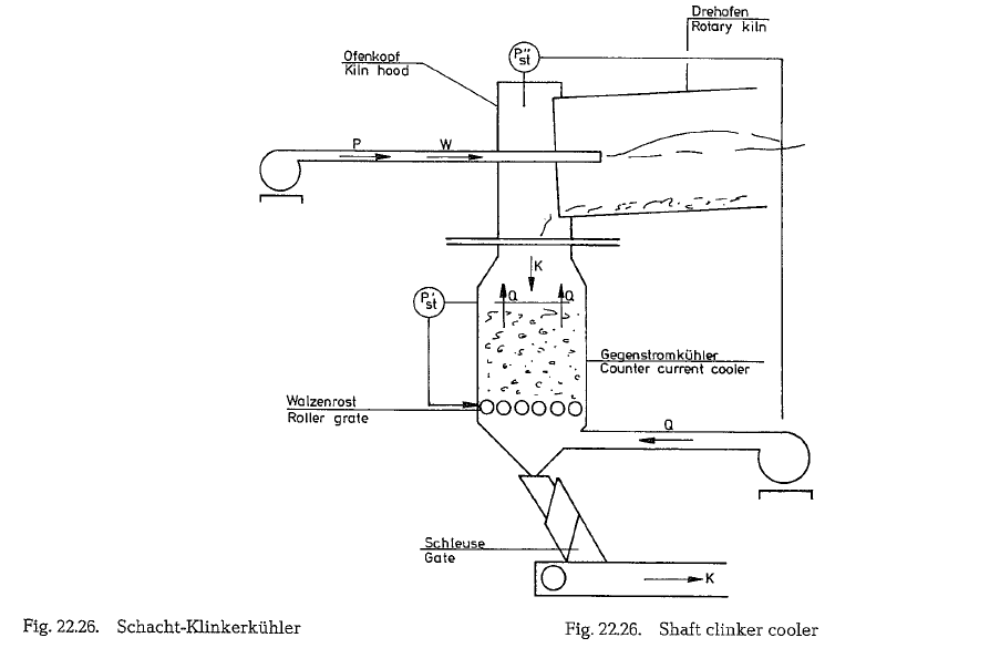
The shaft cooler consists of the following main com ponents: the refractory insulated shaft housing, the roller grate, the discharge hopper, the airtight three compartment discharge gate, and the blower for the cooling air. Pipe and duct connections, as well as measuring and control devices, represent the auxil iary equipment. The upper part of the shaft has a smaller diameter, to increase the velocity of the cool ing air, thus to create, in this area, conditions for a fluidized bed. Due to the fluid bed effect, according to which the material in the upper part of the shaft behaves like a liquid, the clinker entering the cooler from the rotary kiln is immediately evenly distri buted over the total cross-section of the shaft.
Each of the grooved rolls of the roller grate has a separate drive; when necessary, the rollers can be operated with different revolutions, to withdraw the material column with various speeds. Pieces of clinker which are larger than 25 mm, are disinte grated by the crushing action of the rollers.
The cooling air entering the shaft cooler is distri buted as follows: 35 % of the air volume is introduced underneath the grate, 45 % enter at a point of the shaft’s half height, and the remaining 20 % is blown into the constricted part of the shaft. Specially formed pipes and nozzles which penetrate the clinker column, distribute the cooling air uniformly over the shaft’s cross-section.
Fig. 22.26. shows a longitudinal section of Bade’s shaft clinker cooler.
Since the cooling in the shaft cooler is performed instantly, the quality of the clinker cooled in this way equals that of the clinker cooled in a grate cooler, especially where the ratio of C3S :C2S is concerned.
Depending on the quantity of the cooling air, the temperature of the clinker leaving the cooler is about 250-280 oc above ambient temperature. The temperature of the secondary air is in the range of 900- 1000 oc
The static pressure of the cooling air blower is 1120 mm. The quantity of cooling air is 1.1 st.m3/kg clinker.
The specific power requirement is about 8 kWh/t of clinker compared to 5.5-6 kWh/t for the grate cooler; the latter figure includes also the power requirement for the grate drive.
The Research Institute of the German Portland Cement Association determined the thermal effi ciency of the shaft cooler equal to 83 %.
Since there is no excess air, no dust collector is required for the shaft cooler. The headroom of a shaft cooler is 10% higher than that of a grate cooler.
Clinker conveying
Previously, for clinker transportation shaker troughs or vibrating chutes with a high frequency oscillation amplitude were used. However, these troughs or chutes could. be used only for horizontal transporta tion of clinker. For vertical transportation it was necessary to transfer the clinker into bucket eleva tors or into swing bucket conveyors. These clinker conveying machines developed much dust not only during horizontal transportation, but also during transloading in vertical conveyors. These drawbacks motivated the cement machinery manufacturers to develop new-styled transportation arrangements, so-called bucket apron conveyors, which are able to convey the clinker not only horizontally but also on inclinations (mostly 40- 45 a, in exceptional cases even up to 60 °) almost without generation of dust.
One of the presently most used clinker transporta tion arrangement is described as follows.
The Beumer Co. (Beckum, W. Germany) manufactures apron type steel bucket conveyors for clinker tran sportation, having noncontacting overlapping cells, and a special stiffened chain. With this design, the clinker dust which enters the first overlapping line is held back by a raised rear edge of the cell. The cells are modified in such a way that the side plates do not open up when passing over the return station. For inclinations from 28- 45 o each second cell is equipped with an intermediate web plate, and for inclination from 45- 60 o each cell has such web plate.

Fig. 22.27. and 22.28. show this type of clinker conve yor for applications from horizontal transportation up to 28 o inclination and then for gradients of more than 28 o with intermediate web plates.
Fig. 22.29. shows the condition of the steel cell clinker conveyor while passing the return-station.

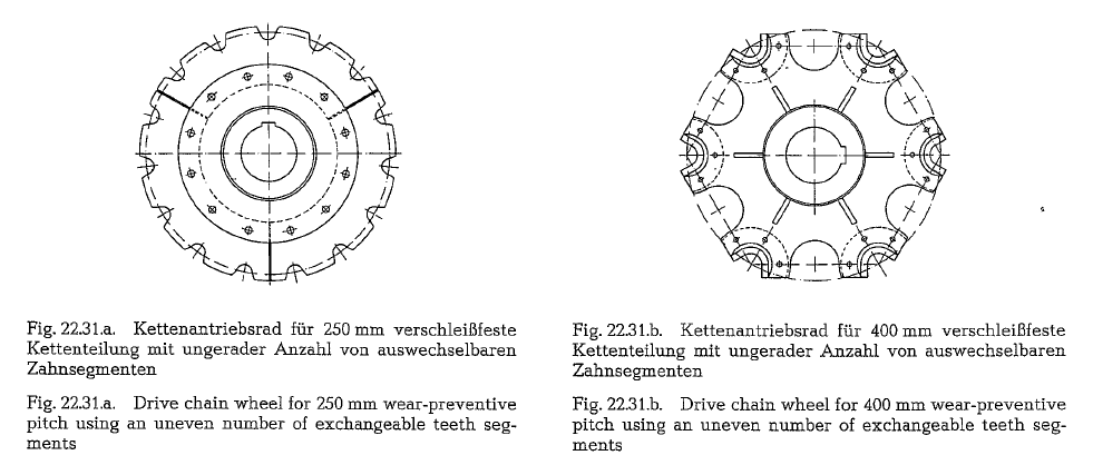
For open and box type cells, a chain of 250 rom pitch is used, and for bucket type cells a chain of 400 rom pitch is applied. To avoid sagging of the 250 rom chain it was stiffened by adding a projection on the outer side bars which rest on a bead on the inner side bar.

Fig. 22.30. shows the chain (250 mm pitch) with the projection and bead to avoid sagging.
The drive chain wheels are equipped with exchange able, flame hardened sprockets (for 250 mm pitch) or tooth shells (for 400 mm pitch) respectively. To reduce the wear on the sprockets, an uneven number of teeth was chosen. This way each sprocket is in act ion only once at two full revolutions of the wheel. Fig. 22.31.a. (250 mm) and 22.31.b. (400 mm) show the form of the two types of sprocket wheels with replaceable teeth
The rollers are running in two grooved ball bearings which are sealed at the inside by lamellar rings. The short roller axle is kept in place by a clamping device with bolts, which allows for a quick exchange of the rollers
Fig. 20.32. shows the wheel arrangement with ball bearings and the clamping device by which the axle is kept in place.


should not run at speeds exceeding 0.30 m/sec. Therefore, when comparing conveying capacities, the chosen speed must be taken into account.
When planning a clinker conveying installation, a filling level of 75-80 % should be considered. When locating the steel cell conveyor directly underneath the clinker cooler, the conveying capacity should cor respond to the normal kiln capacity at a 40-50 % cell filling level to prevent overfilling in case of possi ble kiln ring breakage. However, drive capacity should be set as for 100 % cell filling level. Further, it is important that capacity reduction factors are applied when considering inclined conveyors as com pared to horizontal conveyors. Thus e.g. a horizontal conveyor including an inclination up to 28 o, at a con veyor width of 1400 mm has a conveying capacity of 438m3/h. At an inclination of 60 o however, the con veying capacity drops to 245 m3/h, i.e. to 60 % of the original capacity (Beumer brochure No 55, Hot Material Conveyors).
Standard steel (St. 37.2, DIN 1050) is used for the cells up to a material temperature of 500 °C, that is in the majority of cases. The base plates of cells are 5-6 mm thick, and the side plates are 5 mm thick. The cell height is normally 300 mm.
Fig. 22.27.- 22.33. are from Beumer Co., Beckum, W. Germany.
In the following some pictures of clinker conveying arrangements, and of clinker silos supplied with installations by the Aumund-Forderbau Co., 4134 Rheinberg, W. Germany, are shown.
Fig. 22.34. shows an Aumund steel pan clinker conve yor for discharge underneath the clinker silo. The dis charge capacity is controlled by the material height on the clinker conveyor.

Fig. 22.35. shows a clinker silo with a storage capacity of 230,000 t (metric). This silo is, according to Aumund, the largest clinker silo in the world. The conveying arrangements to this silo were supplied by the quoted company.

Fig. 22.36. shows a modern cone shaped clinker silo constructed of precast concrete parts. Clinker con veying installations for loading and discharge of the silos were supplied by Aumund Co.
Fig. 22.37. shows a detail photograph of modern clinker silos constructed of precast concrete parts.


Fig. 22.38. shows modern clinker concrete silos. In each head part are two large dust collectors for col lecting the dust from the silos as well as from the clinker transfer points. Clinker conveying installa tions are from Aumund Co.
Fig. 22.34.- 22.38. are from the Aumund Conveying Technique Co.
Fly-ash silos
The manufacture of modified Portland cements through the addition of fly-ash during finish grinding has-been accepted worldwide. Such types of cements are described in volume 2, section 9.1.3. of the Cement-Data-Book. Also technical periodicals report about quality research of such cements
Fluctuations in the sale of fly-ash cements as well as seasonal and regional fluctuations in the operation of power generating stations, require large storage capacities, located either at the power station or at the cement plant.
Cold fly-ash which compacts itself after long storage, loses its useful flowability; therefore, storage silos with special installations were developed. The Clau dius Peters Co. developed in cooperation with the Nils Weibull Co. a so-called “Pneumechsilo” in which mechanical and pneumatic conveying equipment is used, and this not only for filling but also for dis charge of the silo; see Fig. 22.39. (Claudius Peters Co.).
The silo is equipped with a central column, around which a bridge crane moves underneath the silo roof. This bridge crane lifts and lowers a reversible trough less screw conveyor and a circular pneumatic conve yor with a telescopic spout to distribute the incoming material.
Instead of a cyclone, the top of the central column is equipped with an expansion compartment, out of which the material flows to the circular pneumatic conveyor. This conveyor moves the material to the telescopie duct, which in turn brings the fly-ash directly to the screw conveyor which distributes it equally as a selected layer over the silo surface.
To discharge the fly-ash from the silo, the operation of the screw is reversed, and the material is fed to the mechanical circular conveyor which operates around the central column. This conveyor empties into open ings of the column, and at this point the fly-ash is pre-fluidized. Pre-fluidization, togehter with aeration at the bottom of the column generate a central flow zone within the center duct, and thus conditions the fly-ash for a trouble free discharge.

The effective silo area in use, as well as the degree of discharge are exceptionally advantageous due to the forced mechanical discharge. The speciiic energy consumption is approx 0.25 kWh/t, even at com pacted fly-ash