Contents
Cyclone preheaters
TO DOWNLOAD THE EXCEL SHEET AND ALL THE OTHER USEFUL BOOKS AND RESOURCES KINDLY CLICK HERE
Cyclone preheaters in the USSR
In the USSR where four-stage cyclone raw mix pre heaters are constructed according to layouts of the Giprocement-Institute, the following formula is used for sizing the preheater cyclones.
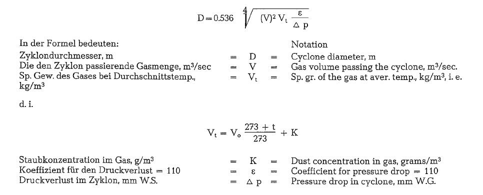
For cyclone raw mix preheaters of Soviet design, a gas velocity in the gas ducts of 15-20 m/sec is applied; the pressure drop is reported to be 520 mm W.G. The exit gas temperature is 200-250 oc. Despite this unusual low exit gas temperature, the specific heat consumption for cyclone raw mix sus pension preheaters of Soviet design is reported to be 950-1000 kcal/kg of clinker, with an energy con sumption for the system of 25 kWh/t of clinker; the dust load of the exit gases is 3 0/o, referred to the weight of the clinker.
Specific heat consumption and energy requirement
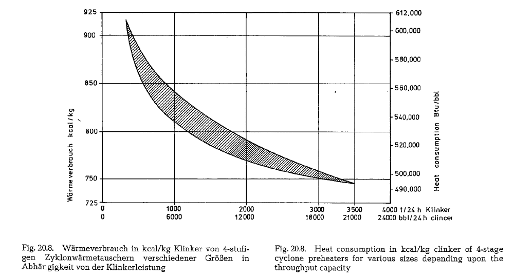
Fig. 20.8. shows the specific heat consumption for four stage cyclone raw mix preheaters of various sizes. Smaller raw mix preheaters show a higher specific heat consumption than larger units. A Humboldt-sys tem with a capacity of about 350 t, shows a specific heat consumption of 920 kcal/kg of clinker, whereas a suspension preheater kiln with a capacity of 3500 t/ 24 h, consumes only 740 kcal/kg of clinker [240]. This shows, clearly that the specific heat losses by radia tion of larger units are smaller; this causes a lower specific fuel consumption, which, in turn, results in smaller heat losses by lower exit gas volumes.
The specific energy consumption of the four-stage cyclone raw mix preheater, in the section from the feeding point into the preheater, to the drag chain of the clinker cooler (including all dust precipitators), amounts to about 20-22 kWh/t of clinker.
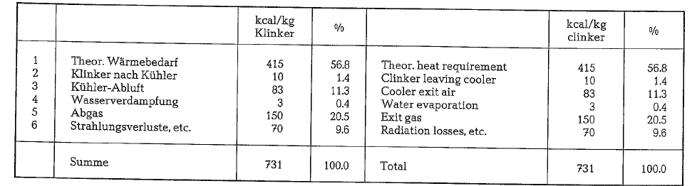
Heat balance
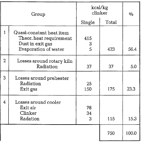
The heat balance of a Humboldt cyclone raw mix pre heater kiln is reported as follows
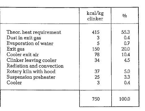
The same heat balance divided into four process-typi cal groups, has the following form
Theoretical heat requirement for clinker burning
The heat economy of the rotary kiln shows the differ ence between the theoretical heat requirement of the clinker burning process, and the real heat consump tion in the rotary kiln. The theoretical heat require ment is the conversion of the dry raw mix into the reaction products of the clinker and the reaction enthalpy connected with this process related to 20 oc and 1 kg clinker, or the conversion of about 1.55 kg raw mix to 1 kg clinker.
The determination of the heat of formation of the cement raw materials, and of the resulting clinker minerals started already in 1906, as the first endea vors were made to determine the thermal reactivity of the clinker burning process. The values ascer tained by various scholars showed often erratic scat terings, since in the course of time the opinions of the scientists concerning the heat requirement of the cement burning process have changed
In the long run complicated and tedious calculating methods for the theoretical heat requirement were developed. H. zur Strassen became convinced that the accomplishment of the complete calculation pro cedure is very laborious, and developed a simplified formula which allows to attain directly the theoreti cal heat requirement from the analytical data of raw mix and clinker
Two formulas were developed, the one without alkali effect, and the other with alkali effect. All raw mater ial components of the clinker are arithmetically con verted into the free oxides, to which the required amount of heat is charged.
The exothermal effect occuring during the process of clinker formation can be calculated from the clinker minerals which again can be determined according to Bogue’s formula based on the clinker analysis [13]. Since for the calculation of the heat effect the explicit knowledge of the clinker minerals is not necessary, they were eliminated from the calculation. Further, it is said that the exothermal effect of the clinker for mation is almost independent on the content of free lime in the clinker; each per cent of free lime in the clinker equals 0.1 kcal/kg clinker. At the low factors of alumina and iron oxide, and their small contents, the influence of these components is also very little. From this it can be concluded that the exothermal effect is almost exclusively determined by the con tent of silica in the clinker.
The thermal effects of the clay minerals are:
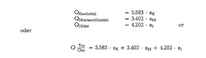
This formula refers to the case in which the heat of evaporation of water is not separately determined. If the content of water of hydration is separately deter mined, and the heat of hydration calculated, then we will obtain:
![]()
![]()
where hH represents the water of crystallization of the clay substance in the raw mix calculated in grams/100 grams clinker. If the clay components are not known, then the average value should be used for calculation. Consequently, the arithmetic mean of the three clay factors should be inserted which results in

If the total alumina originated from the clay sub stance is taken into consideration then the zur Strassen formula obtains the following expression (a possible error resulting from this calculation could be in the range of ± 2 kcal/kg clinker):
![]()
![]()
From the below quoted clinker analysis, the following theoretical heat consumption for clinker burning can be calculated:
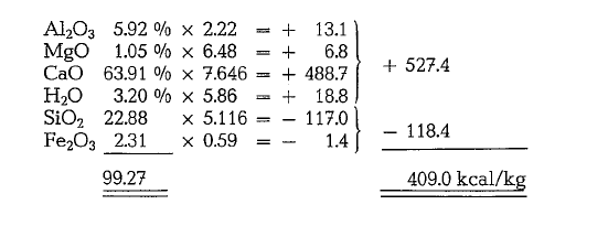
The determination of the alkali effects requires a lit tle more calculation, but based on the quoted zur Strassen’s paper, it can be easily performed. For orientation purposes it may be said that at a moder ate content of alkalies the heat requirement is low ered by about 2 kcal/kg clinker, so that the above calculated heat consumption may amount to 407 kcal/kg clinker.
Since the fuel is one of the most expensive produc tion components of the clinker, and proposal negotia tions are always accompanied with bargaining almost for each single kcal, it is necessary for the kiln manu facturer to perform clinker burning tests with the customer’s raw material, to be able -based on the clinker or raw material analysis – to calculate the theoretical heat requirement. Based on the theoreti cal heat consumption figure the kiln manufacturer is in the position to guarantee practical heat consump tion figures when supplying or reconstructing kiln aggregates. Of course, this refers also to acceptance tests.
The preheater bypass system
Alkalies in cement and in concrete admixtures
It was first learned in the United States in 1935 that destruction of concrete takes effect, caused by a reac tion between the cement’s alkalies and the aggre gates, especially if the aggregates contain about 0.25-5% of components harmful to the concrete. In connection with this, the following admixtures were found to be harmful to the concrete; granite rocks, quartz, feldspar, sand-stone, clay shale, rock mixtures consisting of quartz, chalcedony and opal, tridymite, cristobalite, zeolite, volcanic glass, as e.g. obsidian [243]. Furthermore an American rock called chert or chat, consisting mainly of cryptocrystalline silica with admixtures of chalcedony and opal.
Concrete was damaged in cases where the alkali con tent of the cement was more than 1 %. No damage to concrete was reported with 0.45 0/o alkali in the cement.
It was found that 0.60 % is the highest admissible alkali content in cement, whereby the alkalies are expressed as their molecular equivalent of sodium oxide. Alkali calculation referred to Na20 is arrived at, by multiplying the K20-content by 0.659 and add ing this figure to the Na20-content (molecular weight of K20 = 94, and of Na20 = 62; 94 x 0.659 = 62).Furthermore, the alkali content of the aggregates themselves is not as dangerous as the more easily soluble alkalies of the cement.
Alkalies in the burning process, Alkali recirculation
In suspension preheater kilns more alkalies remain for the time of burning in the kiln system and thus in the clinker, than in other types of rotary kilns. In the course of the burning process, alkalies in the amount of 0.6-2.2% K20 and 0.1-0.7% Na20 coming from the clay minerals of the raw mix and from the fuel, are transferred into the clinker.
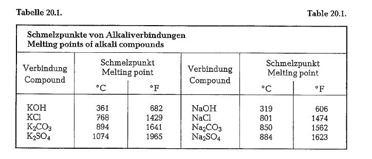
Above approximately, 800 oc the alkalies in the kiln start to volatilize. Table 20.1. contains melting points of various alkali compounds.
However, part of alkalies, i.e. the most temperature resistant, remain in the clinker and appear in the fol lowing clinker minerals:
![]()
![]()
The volatilized alkalies arrive in colder kiln zones where they condense on the colder kiln feed, which in preheater kilns takes place already in the IV. and III. preheater stage. The K20 especially condenses in the preheater at a rate of 81-97 %, whereas the Na20 condenses at a lower rate. This means that 3-19 % of the alkalies leave the preheater kiln [247]. Consequently, the dust carried out from the kiln by the exist gases has an appropriately low alkali con tent, and can be returned into the kiln.
The condensed alkalies arrive with the preheated raw mix along the material path in kiln zones with higher temperature, where they again volatilize. This causes the so-called internal alkali circuit or cycle, in contrast to the so-called external alkali circuit, which is produced by returning alkali laden exit gas dust together with the raw mix into the kiln.
When diverting part of the gases through the so-called bypass-valve, i.e. by sidetracking part of the gases in the lowest part of the stage IV gas duct, it is possible to lower the alkali circuit and thus to reduce the alkali content in the clinker. However, the alkali laden kiln dust turned aside through the bypass, can not be returned into the kiln and must be either dis carded or leached.
Because of the investment cost of the bypass arrange ment and the negative influence of the bypass on the kiln”s heat economy, not more than 25 0/o of the kiln exit gas volume is diverted through the bypass-valve. More than 25 % bypass volume yields only a rela tively low alkali reduction. In most cases a smaller bypass volume of about 3-10% will be sufficient. However, bypass operation increases heat consump tion as well as power requirement.
The incerase in heat consumption caused by the bypass operation amounts to 4-5 kcal/kg of clinker, per 1 % bypass volume. The additional energy con sumption is about 2 kWh/t of clinker, independent of the bypass volume. The kiln dust turned aside by the bypass-valve amounts to approximately 1 % referred to the weight of the raw mix, per 10% bypass volume.
The temperature of the bypass gases at the bypass valve is about 1100 oc. The chemical behavior of the alkalies requires the use of cold air for cooling the bypass gases down to about 475 oc. Cooling can be performed by water spray from this temperature down to 285 o C. which is the admissible entrance temperature into a glas fabric dust collector.
Ritzmann [252a] determined the amount of alkali and SOz-circulation by experiment and by practical mea surements on existing plants of the two kiln systems, namely on 10 Lepol kilns and on 16 Dopol preheater kilns. The degree of adsorption and the rate of volatil ity of the raw mix and the circulating compounds (Na20, K20, S03 and Cl) were also determined, apply ing experimental and numerical methods. Based on these figures, the named author developed formulas to calculate the alkali and chlorine circulation. In addition, it is possible to determine the sulfur cycle, the S03-content of the clinker, and the S02-content of the raw gas and dust, along with their effects upon the operational reliability of the preheater.
Volatility of alkalies
In numerous experiments it was found that:
- The volatility of alkalies increases with an increase in the burning zone temperature, and with the extension of the retention time in the burning zone
- In the sequence of the alkali carriers in the raw mix, e. illite, mica, orthoclase, the volatility of the raw mix alkalies decreases.
- Increasing S03-content in the raw mix and S02- content in the exit gases causes a decrease of the volatility of the raw mix alkalies as well as of the circulating alkalies.
Cl contained in the raw mix as well as in the kiln gases, and water vapor in the kiln gases, increase the volatility of the alkalies. Above all it is the Cl which increases the volatility of the circulating alkalies. For this purpose Cl is added in the form of calcium chlor ide in various ways:
- To the raw mix in the raw grinding mill
- To the raw mix before feeding the kiln
- Injecting of 30 % CaC12-solution underneath the burner pipe into the rotary kiln
- Injcting of CaC12-dust to the secondary air.
Addition of calcium chloride to the raw mix for the purpose of alkali reduction was practiced in America for the first time in 1937 by Dr. L. T. Brownmiller; this was accomplished in a cement plant in Birmingham, Alabama.
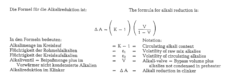
Alkali bypass calculation
According to Weber [247], the alkali bypass calclation is performed under the following assumption: Alkali content in raw mix = 1, and alkali content in fuel = 0.
The formula for the alkali circulation K is:
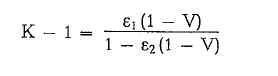
Each alkali component (K. Na) is separately calcu lated with the relative volatility rates or volatility factors 101 and s2 respectively. The same formulae can be used for the calculation of non-alkali substances as sulfur and chloride components.
The volatility rate of the alkalies e1 can be deter mined analytically. The volatility of the circulating alkalies 102 on the other hand, is hardly determinable. However, in any case s2 is equal or larger than Et, since this value refers to components which already were volatilized.
Typical volatilization factors are (see table 20.2.).
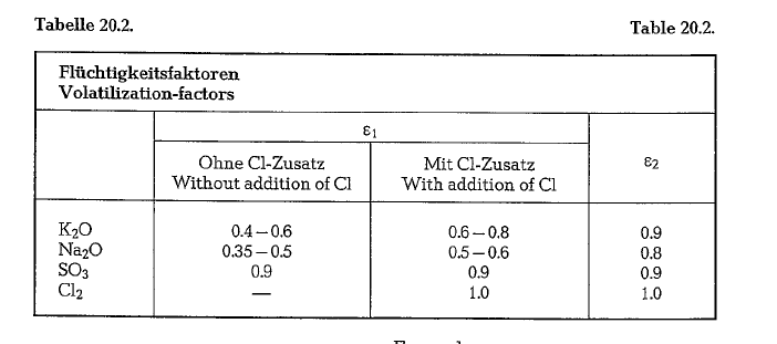
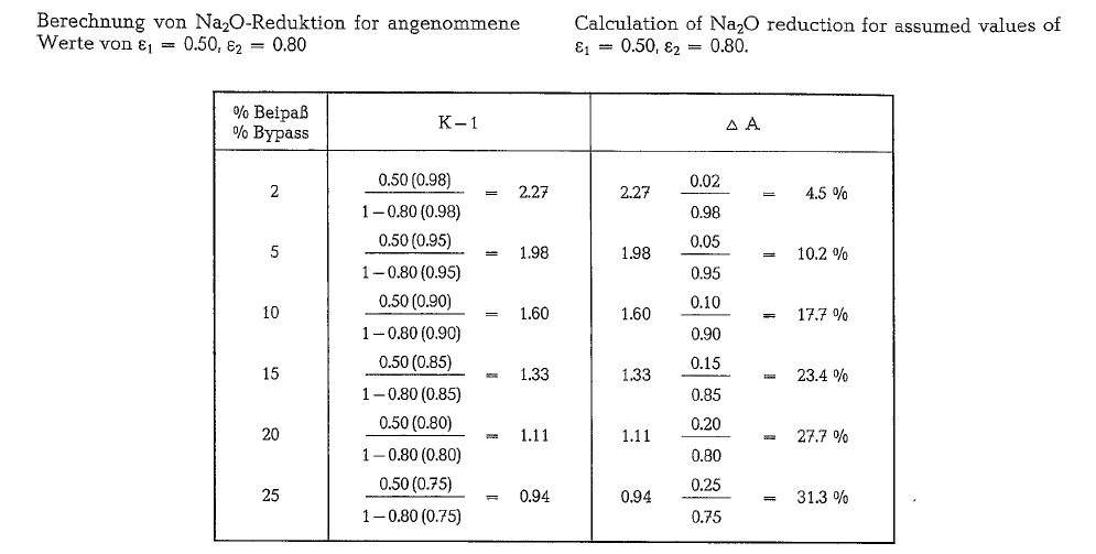
Typical volatilization factors are (see table 20.2.).
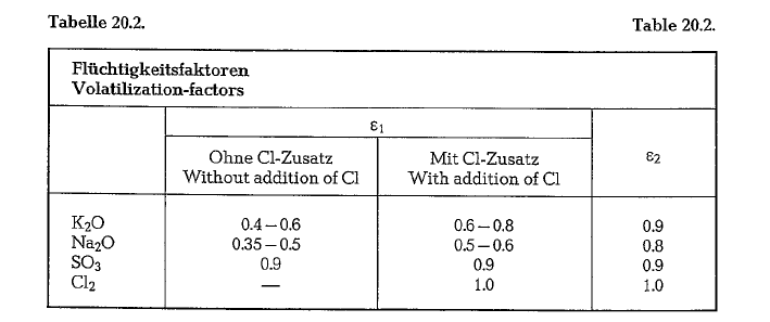

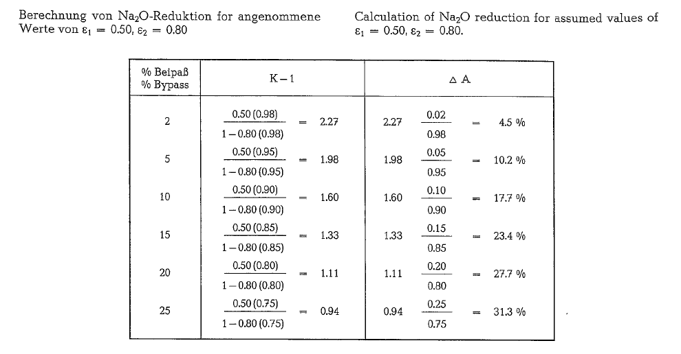
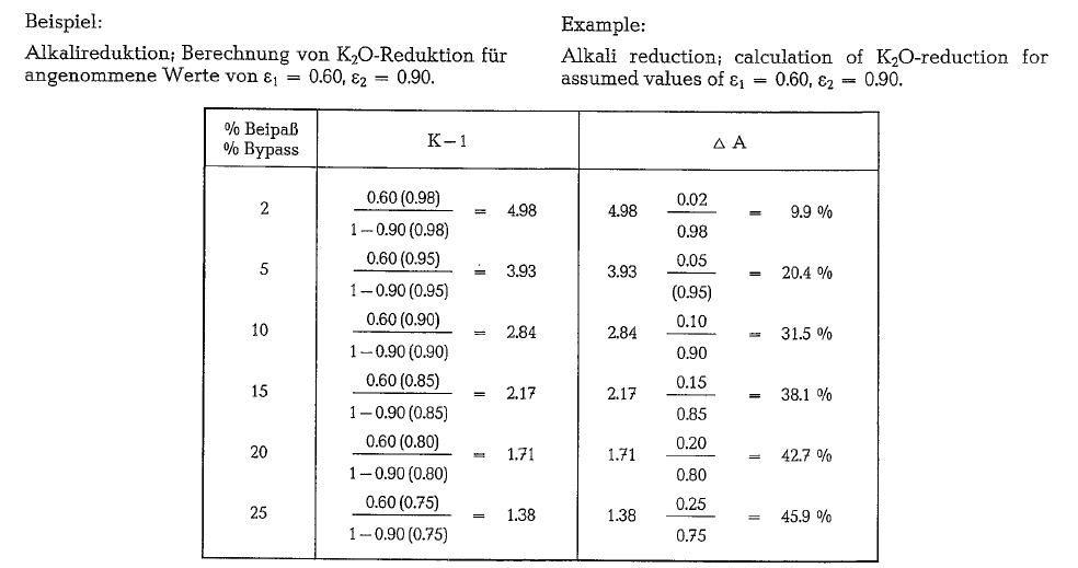
Under the assumption that without bypass operation the alkali content of a certain clinker is K20 =1.25 0/o, and Na20 = 0.32 0/o, the same clinker with bypass operation will show the following contents of alkalies:
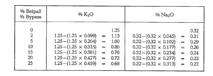
Applying 25 0/o bypass volume, an alkali content of 0.68 x 0.659 = 0.45 for K20 can be attained. Adding the Na20-content of 0.22 0/o, a total alkali content of 0.67 0/o results; this is 0.07 0/o above the limit required for an American low-alkali cement. Therefore, it will be advisable to add to the raw mix Cl in the form of CaC12 to attain a higher volatility of the raw mix alka lies and thus a higher rate for e1 of about 0.70 to 0.75 (see table 20.2.). The amount of CaC12 addition is determined by the laboratory. An addition of about 0.25 0/o Cl, referred to raw mix, increases the alkali volatility and reduces the alkali content in the clinker by about 0.2 0/o. An increase in the tempera ture of the burning zone also results in a higher value for e1• By extrapolation· of the relevant data [252], it can be found that an increase in the temperature of the burning zone from 1450 to 1500 oc, results in a raise of the e1 and e2 values by about 26 %.
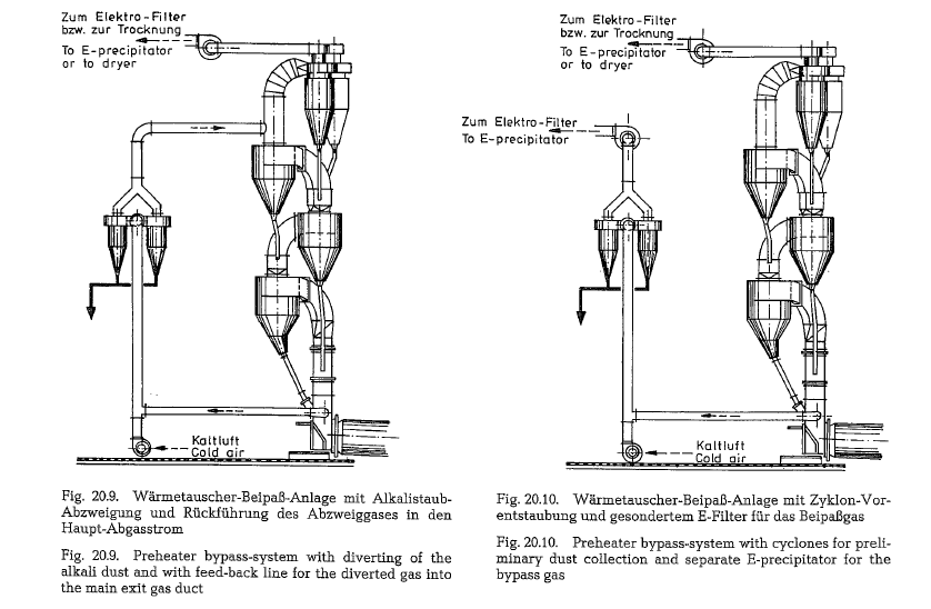
Design models of bypass arrangements
The following illustrations show various design models of bypass arrangements for cyclone raw mix suspension preheaters.
Fig. 20.9. presents a preheater bypass arrangement where the alkali laden dust of the bypass gas is separ ated in cyclones; the cleaned gas is then reunited with the main gas stream. The alkali laden bypass dust is usually either discarded or leached.
Fig. 20.10. presents another design type of a preheat er bypass arrangement; here the bypass gas is first precleaned in cyclones and is then led into a separate E-precipitator for final precipitation. In this case, the main gas stream is more suitable for raw material drying than in the arrangement shown in Fig. 20.9.
Fig. 20.11. presents a third design type of a bypass arrangement; here the bypass gas is led directly into a separate dust collector.
The choice of the most suitable design type of a bypass arrangement depends on the chemistry of the raw material as well as on the volume of the bypass gas.

Fig. 20.1l.a. shows the schematic arrangement of a bypass-system. Applying the adjustable orifice, the bypass rate can be changed in a wide range [259n].
Here it should be mentioned that a suggestion was made to condense the rotary kiln alkalies on cold sur faces; this was confirmed by experiments with exist ing preheater kilns. In this way it is possible to selec tively extract alkalies from the kiln exit gases [253]. However, up to the present time the proposed method did not find practical application.
Two and five stage cyclone preheaters
Cyclone preheaters are predominantly built as four stage units. When modernizing or reconstructing older cement plants, or when converting from wet to dry production process, two-stage cyclone preheaters are often added to existing rotary kilns to improve heat economy as well as kiln capacity. Because of the length of the rotary kilns, and the two stages of cyclones, the temperature conditions differ from that of a conventional four stage cyclone preheater.
Fig. 20.12. shows temperature curves of a two-stage suspension preheater kiln. The original wet process rotary kiln was converted to a dry process kiln by adding two cyclone preheater stages. This change increased the original wet process kiln capacity from 380 t/24 h up to 600 t/24 h, i.e. by 58 %.
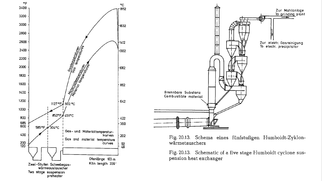
Up to the present time there exists only one unit of a five stage suspension preheater which was erected by the Humboldt Company in 1965/66 in a German cement plant [254]. Here, there is the problem of spe cific raw material conditions, which require separate feeding of one raw mix component (oil shale as argil laceous component), into the suspension preheater; after combustion of the oil content, the remainder of the shale gets mixed with the limestone component. To support the combustion, hot air drawn from the clinker cooler is introduced into the precombustion chamber. Because of the content of combustibles in the raw mix, it was possible to shorten the rotary kiln by 8 m, i. e. to kiln dimensions of 4 x 56 m, instead of 4 x 64 m. Fig. 20.13. shows the schematic of a five stage cyclone suspension preheater.
Various preheater systems
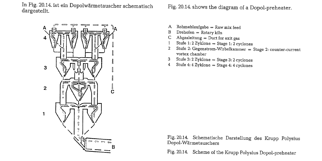
Dopol-preheater of the Krupp Polysius
The Polysius Dopol-Process is a suspension preheater process for preheating of cement raw mix in a dual current suspension preheater, which was developed by the Polysius Company. The designation Dopol is formed by combining the initial syllables of the words Doppelstrom (dual current) and Polysius. The first and third stages (counted from the bottom to the top), consist of parallel arranged double cyclones. The second stage, the so-called turbulence shaft, consists of one cyclone. Depending on the capacity, the fourth stage is supplied with one, two, or four cyclones. Splitting the gas stream into two lines, allows the application of smaller cyclones for the same gas vol ume with a higher degree of separation. When devel oping the double cyclone system, the main goal was to achieve very large kiln capacities without funda mental changes in the design of the system, and with out the application of several preheater lines working in parallel; at the same time a better separating effect was hoped for. To prevent an irregular preheating in the double cyclone lines, the two raw mix streams are led into the common turbulence shaft (second stage) for an intensive mixing. Dopol preheater kilns were supplied up to the present time with capacities up to 7,200 t/24 h.
For clinker capacities below 2000 t/24 h, Krupp Poly sius manufactures, besides the dual current suspen sion preheater, also one line cyclone preheaters.
The following tabulation shows a heat balance of a Dopol-preheater kiln with a capacity of 4000 t/24 h
The power requirement of a four-stage Dopol-prehea ter kiln, from the raw mix feeder into the preheater to the clinker cooler discharge chute, is quoted to be 13 kWh/t of clinker, with an exit gas volume of 1.3 st.m3/kg of clinker and at an exit gas temperature from the preheater of 310 °C.
The 0+K raw mix preheaters
Besides the conventional 4 to 5 stage preheaters 0 +K offers an improved modification of the pre heater, system Miag. 0 +K is short for Orenstein and Koppel AG, Ennigerloh, West Germany.
The 0 +K raw mix preheater (System Miag) consists of three or 4 cyclones respectively working in paral lel current, and of one conical preheater shaft as a last stage, with counter current heat exchange.
For a capacity up to 1500 t/d the preheater is designed as one-strand preheater; for larger capaci ties two-strand preheaters are applied.
The working principle of this raw mix preheater is schematically shown in Fig. 20.15.
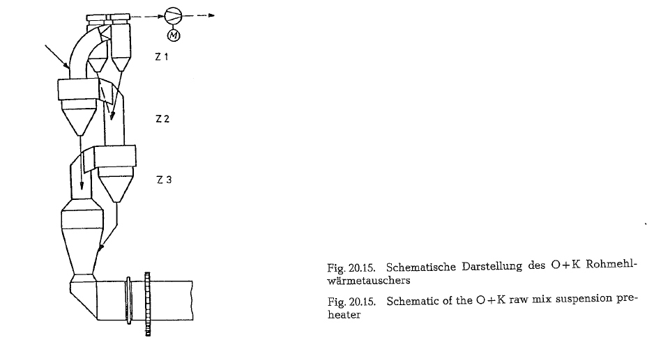
Concurrently with the gas flow, the raw mix is fed into the preheater, ahead of the upper cyclone stage (Z 1). From here, it passes all consecutive cyclone stages, down to the rotary kiln. On its way to the rotary kiln, the raw mix comes in close contact with the always hotter kiln exit gases. After passing the lowest stage, the raw mix is preheated to about 800 o C.
The raw mix separated in stage Z 3, is conveyed into the vortex chamber, which is also called conical pre heater shaft. One part of the raw mix which flows to, or is already inside the preheater shaft, is once again conveyed into stage Z 3,- by the upward flowing kiln exit gases. The raw mix recirculation extends its retention time in the hottest zone of the preheater, thus intensifying the heat transfer from the kiln gases to the raw mix; as a result, precalcining degrees of more than 50 % are attained.
Inside the preheater shaft, the material increases its concentration in the gas stream, until it continuously precipitates as a so-called dust cloud through the kiln transition compartment into the rotary kiln, in coun tercurrent to the direction of the gas flow.
Designing the fourth stage as a conical preheater shaft, results -according to the manufacturer -in a considerable operating advantage, as compared to a conventional cyclone preheater. Whereas in a cyclone preheater, the preheated raw mix is led from the lowest cyclone stage through a duct with a cross section of only about 0.5 m2 to the transition compart ment, the free passing cross-section between the con ical preheater shaft and the transition compartment is up to 14 times larger.
If the raw mix shows higher concentrations of alka lies (K20, Na20), chlorides, and sulfates, this large cross-section is of specific advantage. The quantities of so3 and alkalies introduced additionally into the system by the fuel, especially when applying coal dust firing, often cause in the kiln-preheater system an intensive recirculation of the volatile components,
and condensation as well as concentration in the colder zone of the system, which results in caking. Since the caking occurs mainly in the kiln-preheater transition zone, and also in the lowest cyclone stage, sometimes considerable operating disturbances can develop, by plugging the relatively narrow raw mix duct.
Because of the large cross-section of the countercur rent stage, the described problem did not occur, even at higher concentrations of the above mentioned components.
Even if the concentration of the disturbing compo nents increases, or if low-alkali clinker should be manufactured requiring the application of a gas bypass, the relative indifference to caking and plug ging, due to the large exit gas cross-section, is a con tributing factor that the volume of the bypass gas be kept to a minimum. This increases the economy of the system, since it is known that each percent of bypass gas, increases the specific heat consumption.
The specific heat consumption of the 0 +K raw mix preheater is quoted to be in the range of 750-800 kcal/kg of clinker.
In Spain, the ATEINSA Co., Madrid, manufactures 0 +K raw mix suspension preheaters as licensees.
The ZAB raw mix suspension preheater
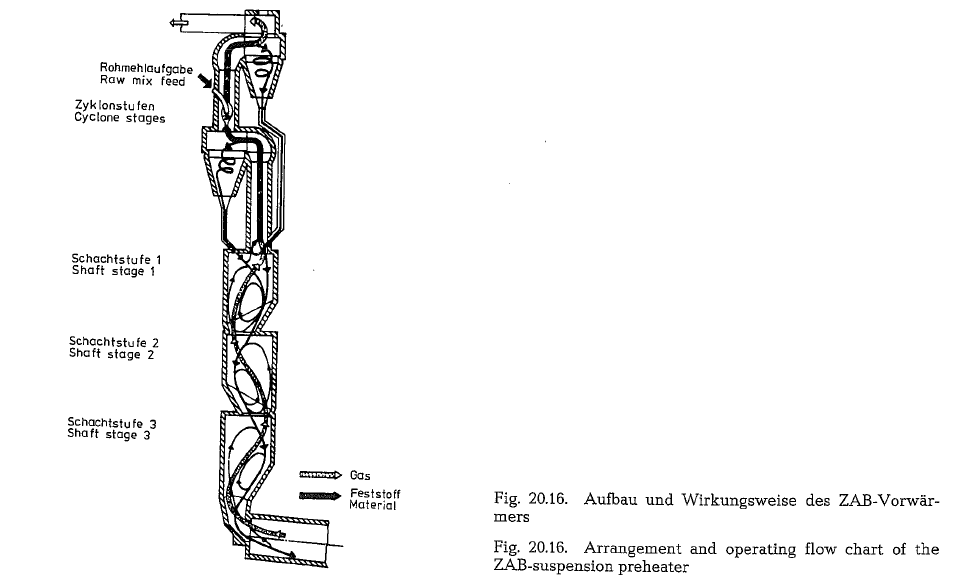
The suspension preheater of the SKET/ZAB Co., Des sau, consists of three shaft stages as well as of two cyclone stages, located on the top (255b, 255c]. Two procedures run its course in the shaft stages: the heat transfer process, and preferably the technological processes, whereas the cyclone stages are assigned for a methodical termination of the heat transfer and transportation procedures (Fig. 20.16.). The shaft stages are characterized by their oval cross-section and by the fact that their vertical axes are arranged in a staggered way to each other.
Schematically, the raw mix moves in the form of a strand, preferably within the peripheral zones down to the kiln inlet, and in countercurrent to the gas stream. In doing so, only one part of the raw mix enters the respective lower stage, whereas the other part is carried up with the gas stream, and, depending on the separation capacity of the particular shaft stage, is conveyed again to the primary raw mix stream, or can also enter the lower shaft stage. In this way, strongly marked material circuits are formed, not only in the particular shaft stages but also between these stages, which support generating of chemical reactions. This type of preheater allows a chloride concentration in the raw mix of 0.025 % troublefree, and without any bypass operation.
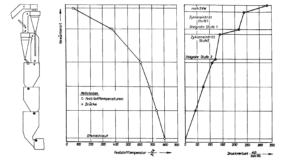
Due to the simple design of the gas conducting pre heater parts, the static pressure drop of the ZAB pre heater of 250-400 mm WG (see Fig. 20.17.) is low, when compared with other preheater systems at sim ilar temperature conditions.
According to literature references, the ZAB-prehea ter is characterized by its high operating safety in relation to volatile components of the cement raw mix [255g, 255h]. The reasons for this are:
- The existence of large space shaft stages, resulting in a minimum of gas deflection.
- A constant, intensive contact of both phases
- The combined conduct of the material and gas stream in the transition zone of preheater and rotary kiln.
The ZAB-preheater is manufactured in single tower and in twin construction. Up to a clinker capacity of 2000 t/24 h, the single tower construction proved to be sufficient.
Manufacturers of shaft-type raw mix suspension pre heaters claim that, contrary to cyclone-type raw mix preheaters, the wide spaced shaft stages, especially in the lower part of the preheater, are less sensible to caking of alkali condensates, since shaft preheaters promote precipitation rather on the raw mix stream, and are therefore allegedly easier to operate. Recent publications try to present the different compatibility of alkalies in cyclone- and shaft-type raw mix prehea ters.
The Gepol counter-current suspension preheater
The suspension preheaters described so far, work on the principle of a stepwise parallel current, or are supplied with one or two counter-current stages, where so-called vortex chambers serve the purpose of counter-current heat transfer. The preheater devel oped by the Krupp Polysius Company (see Fig. 20.18.) is an almost complete counter-current heat exchan ger, except the uppermost stage which, for the separ ation of dust, is constructed as a double cyclone stage supplied with a duct for the ascending gas; the remainder of the preheater is a cylindricaL self sup porting shaft. Nozzle type constrictions divide the shaft into four compartments. Above each constric tion there is a conical structure for even distribution of the descending raw mix. In this way, the preheater actually works in five stages. The feeding point of the raw mix is located between the uppermost preheater compartment and the cyclone stage, from where the raw mix is carried upwards by the gas stream, pre heated, separated in the cyclones, and supplied into the uppermost preheater compartment; from here the raw mix descends from compartment to compartment into the discharge shaft, from where it finally enters the rotary kiln. Due to the constrictions between the compartments and the resulting higher velocity of the ascending gas, the raw mix is kept for a moment in each compartment -until saturation -in a state of suspension; this extends the residence time and improves the heat transfer. This procedure is repeated four times. In the individual stages of the Krupp Polysius counter-current raw mix suspension preheater, the following gas temperatures prevail
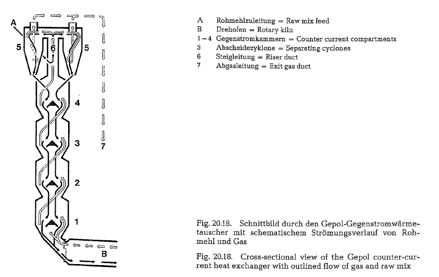
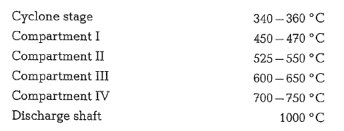
Fig. 20.18. shows a longitudinal section through a Krupp Polysius counter-current suspension preheater with outlined flow of raw mix and gas.
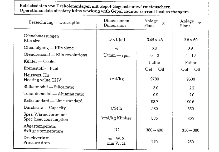
The specific heat consumption of the Krupp Polysius counter-current suspension preheater is quoted to be 800- 900 kcal/kg of clinker.
Operating capacities of Krupp Polysius counter-cur rent suspension preheaters (Gepol-preheaters) are in the range of 1650 t/24 h.
The large cross-section of the Gepol counter-current suspension preheater and the corresponding low velocities of the ascending gases, cause a relatively low pressure drop of 270 mm W.G.; from this, 40 % is apportioned to the pressure drop in the preheater shaft, and 60 % to the cyclones with the gas ducts. The specific power requirement of the total arrange ment is 16.9 kWh/t of clinker [257]. Here is should be noted that at different plants, data concerning the consumption in kWh/t do not always include the comparable line of machinery. The figures differ quite noticeably, depending on whether the dust collectors and the raw mix or clinker conveying machinery are included. Even dust collectors show different power consumption relative to their type or model.
The specific power requirement for the ID-fan of the arrangement S, cited in Table 20.3., amounts 3.5 kWh/t of clinker; the dust load of the exit gas is 38 g/st.m3, and the total heat loss by radiation is 80 kcal/kg of clinker.
Table 20.3. contains operational data of two rotary kilns with Gepol raw mix suspension preheaters.
The dimensions of a Gepol suspension preheater for a capacity of 1650 t/24 hare: 7.8 m diameter (measured on the shell, 7.3 m diameter on bricks) and roughly 65 m height. The diameter to height ratio is 1 : 8. The outer surface of the shaft tower is 1530 m2. Compared to this, the outer surface of an equivalent four-stage cyclone preheater is according to Krupp Polysius 1810 m2•
The counter-current suspension preheater of the Pferov Engineering Works, Pferov, Czechoslova kia
This counter-current raw mix suspension preheater consists of a vertical shaft with counter-current heat exchange, of two stages of double cyclones, and of a gas duct from the shaft to the cyclones. The upper most cyclone stage consists of two dust collection cyclones, whereas the lower two cyclones serve the purpose of recirculating and preheating the raw mix. A gas duct leads the kiln exit gases tangentially into the preheater shaft, thereby giving the gases a helical motion. This should, for maximum heat transfer, im part a turbulent flow to the descending raw mix. To obtain a possibly complete dispersion of the raw mix in the preheater shaft, the gas duct protruding from the shaft, contains in its lower part a dispersion cone, for the purpose of scattering the raw mix evenly along its circumference.
This heat exchanger is characterized by its simple construction and method of operation. Expansion joints are not present; this circumstance reduces the intake of false air to a minimum.
The refractory lining consists mostly of standard size bricks. The self-supporting construction requires a small foundation base, which considerably lowers the construction cost. The energy cost is low, since the pressure drop at full operation does not exceed 350mm WG.
The kiln exit gases enter the heat exchanger at a temperature of 950-1050 °C; the maximum temperature of the preheater exit gases is 360 oc. The dustcontent of the preheater exit gases is in the range of 30-50 g/st.m3.
The thermal efficiency of the preheater is initially determined by the ratio of the shaft’s height to its diameter. This ratio is selected to ensure the most favorable relation between investment and operating cost. The shaft’s diameter is determined by the gas flow requirements
According to the manufacturer, this preheater absorbs temporary variations in the amount of gases without operating difficulties.
Fig. 20.19. Arrangement of the counter current raw mix preheater of the Prerov Engineering Works
At the present time, the following preheater sizes are supplied by the manufacturer (see Table 20.4.).
Fig. 20.19. shows the arrangement and the mode of operation of the countercurrent raw mix preheater of the Prerov Engineering Works (Czechoslovakia).
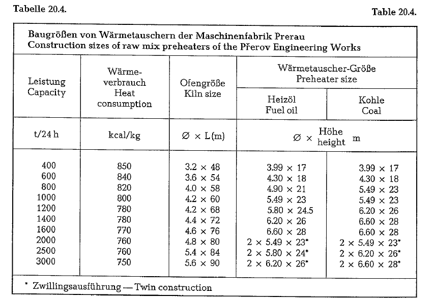
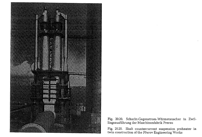
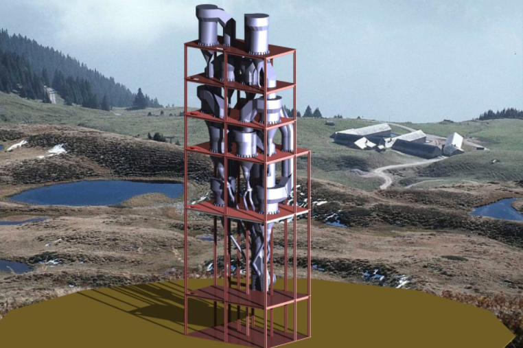
Fig. 20.20. shows the total view of the Pferov counter current shaft type preheater in twin construktion with a clinker production capacity of 2000 metric t/24 h. Here, it should be mentioned that the Pferov Engineering Works manufactures complete machi nery and equipment for cement plants.
Nice massage sir
Please send more details of about rotary kiln ,5 stage pre heater and grater cooler sir