Contents
Rotary kiln Support roller bearings Erection
[wpecpp name=”package + Updates forever” price=”250″ align=”center”]
1.0 Introduction
The rotary kiln support roller bearings are self-adjusting journal bearings. The ball
race of the bearings constantly ensures full and even axial contact between bearing
liner and journal, even if one bearing is displaced relative to the other, whether
occurring in the vertical or in the horizontal direction.
Lubrication is based on the hydrodynamic lubrication principle, i.e. with formation
of a supporting oil film between bearing liner and journal during rotation. It is
essential to ensure a diameter differential between journal and bearing liner which
makes it possible to attain the wedge action required to build up the supporting oil
film between journal and liner. Equally essential to the hydrodynamic function is the
dependency upon the viscosity of the oil. Therefore, it is essential to emphasize the
importance of ensuring strict compliance with the directions given in the lubrication
manual.
References to instruction manuals
In the text of this instruction manual, reference is made to an instruction manual
reference No. where this is deemed to be relevant.
The titles of all instruction manuals referred to are listed on the front page of this
instruction manual, with indication of the number referred to.
Reference to other instruction manual numbers is done via the ”General kiln instruction
manual”, ref. 1 in which relevant instruction manual numbers can be
identified on the basis of the title of the relevant manual.
1.1 Operating principle
DESIGN AND OPERATING PRINCIPLE
See Appendix 1, Appendix 6, Appendix 7, Appendix 8, Appendix 9 and Appendix 10.
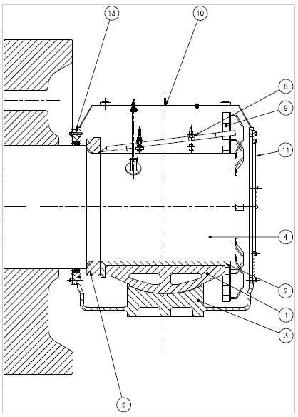
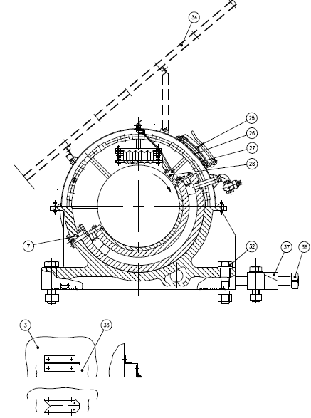
The bearing housing consists of a cast-iron base part (3), a mild-steel top part (10)
and an end cover (11).
The base part is fixed to the bedplate by bolts (32). It is equipped with a lubrication
oil sight glass (21) and a plug (23) for draining of oil and carries a cast-iron ball
socket (1) which forms the support base for a bronze bearing liner (2). The ball
socket rests on a spherical face and it is retained by means of a guide pin (7) so
that the dividing face of the ball socket forms an angle of 30° to horizontal. The ball
socket has internal chambers through which the cooling water is circulating.
The bronze bearing liner (2) has a fixed thrust collar provided with oil pockets (see
Fig. 3 in Appendix 1. The thrust collar must be oriented to face the supporting
roller’s thrust ring (5) which is shrunk onto the support roller journal, close to the
roller hub.
Two inspection ports (25) in the top part provide access for inspection of the bearing
as well as of cooling water inlet and outlet connections, breather pipe with air
filter (12) and thermal sensor (28) suspension parts.
To prevent infiltration of dust into the bearing a three-part seal (13) is fitted around
the opening of the support roller (4) shaft. Rubber bushings (29) around the cooling
water connections prevent dust infiltration here.
The bearing is protected against radiant heat from the kiln either by means of large
heat shields for protection of machines and personnel, or by smaller heat shields.
Internal transport of lubricant is effectuated by oil cups (9) fitted to a ring screwed
onto the bearing journal. During rotation the oil cups scoop up oil from the bottom
of the bearing housing to an oil tray (8) which distributes the oil across the bearing
journal, see Appendix 6.
During standstill the supporting roller journal rests, theoretically, on a generatrix of
the bearing liner. When the shaft rotates oil will be drawn into the wedge-shaped
clearance between shaft and bearing liner. At a certain speed sufficient oil will be
drawn in to form an oil film able to completely lift off the journal from contact with
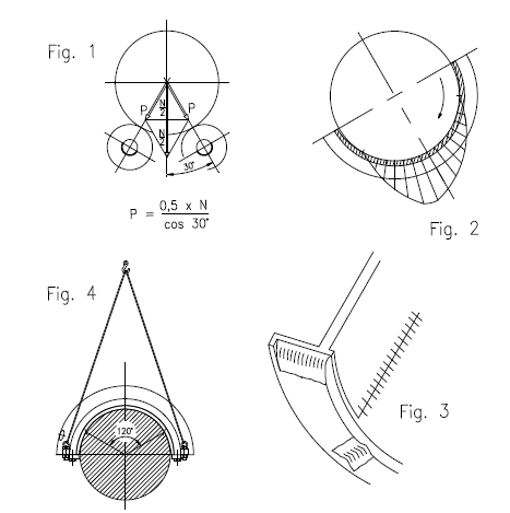
the liner. This wedge action, generally named as hydrodynamic lubrication, produces
a characteristic pressure distribution in the oil film similar to that shown on
Fig. 2 in Appendix 1. Depending upon speed and temperature, the minimum oil film
thickness may approach 0.01-0.02 mm.
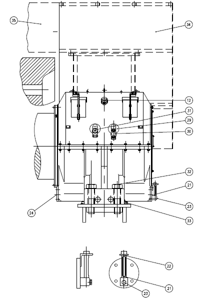
The bearing is continuously water cooled. Cooling water flows through the water
chambers of the cast-iron ball socket (01). A flow indicator (30) mounted at the
cooling water discharge branch means that it is possible to monitor the cooling
water flow; see Appendix 7.
The cooling water flow must be set for each bearing by adjustment of a three-way
control cock (31) provided with T-bore and a vent opening. When this cock is used
to shut off the water flow, the ball socket water chamber will be connected –
through the cock – to the atmosphere. The outlet pipe, the mouth of which is
located at level below the bottom of the water chambers will thus be acting as a
siphon, thereby draining the chambers of water.
If temperatures below the freezing point are anticipated and/or if a prolonged
shutdown is required the water chambers must be emptied. The outlet pipe will
only be able to act as a siphon if the cross-sectional area of the pipe is “filled” with
water, i.e. just prior to shut down for emptying, the cooling water supply must be
fully opened.
2.0 General notes
REQUIREMENT:
-Machine to be used exclusively for the purpose for which it has been designed.
MANDATORY
-The directions outlined in ref. 3 must be strictly observed at the site of erection.
This instruction manual must be scrutinized by the client, the erection contractor
and FLS representatives before erection work are started.
References to instruction manuals
-In the text of this instruction manual, reference is made to an instruction manual
reference No. where this is deemed to be relevant.
The titles of all instruction manuals referred to are listed on the front page of this
instruction manual, with indication of the number referred to.
Reference to other instruction manual numbers is done via the ref. 1 in which
relevant instruction manual numbers can be identified on the basis of the title of
the relevant manual.
Erection inspection
-Quality control! The words “Erection inspection” in any drawing or text mean that
the erection supervisor must carry out an inspection and approve erection status
before continued erection may commence.
Attach return cable
-In connection with arc welding and when operations involving blowtorching with
gouge are carried out, the return cable must always be attached to the object
subjected to welding, as close as possible to the area of welding.
The return cable must never be attached in a way which will cause the return
current to be passed through parts not connected to the object being welded, for
example: moving parts, bearings, electrical installations or any other parts.
A return current through a bearing may give rise to welding scars which will cause
severe damage to bearing.
A return current through electrical installations may cause serious damage to
protective earth lines (extremely hazardous condition!) or electronic equipment.
ERECTION CHECK
-Where ERECTION CHECK is specifically called for in the erection manual, this means
that the FLS erection supervisor must inspect and approve the parts mounted
before permission to precede with erection work can be given.
3.0 Installation
Installation inspection
-Quality control! The words “Installation inspection” or “Erection inspection” in any
drawing or text mean that the installation supervisor must carry out an inspection
and approve installation status before continued installation may commence.
3.1 Prior to installation
Carefully remove the protective paint or rust-proofing compound from the spherical
faces of ball socket (1), base part (3) and support roller shaft journal (4). Use a
high-aromatic solvent e.g. ESSO’s Solvesso 100. Paraffin oil must not be used
because of its rust-promoting properties. Immediately following this suitable lubricant,
e.g. FLS MAT 7157 (EP 680) or FLS Mat 7158 (EP 1000) must be applied to
the above-mentioned spherical faces and journal.
Do not remove the rust-proofing paint from any bright surface until the installation
of each specific component is imminent. Rust will be formed on any unprotected
surface within a very short time period. On completion of installation procedures,
lubricant must be applied very carefully to all bright surfaces, thereby minimizing
the risk of rust formations.
3.2 Bearing liners
The bronze bearing liner (2) must be dismantled from the ball socket (1) and the
surfaces cleaned very carefully. Use a solvent similar to the above-mentioned
ESSO’s Solvesso 100. It is extremely important that the contacting surfaces between
ball socket and bronze bearing liner are completely clean when they are
remounted.
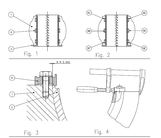
When remounting be sure that the bearing liner (2) is correctly orientated in the
ball socket (1) dependent upon the position of the bore for the guide pin (7). The
stop irons (6) must be orientated as shown on Fig. 3, Appendix 9 and the stop iron
bolts tightened according to the torque level indicated on the assembly drawing and
in the sequence, 6A-6F, shown on Fig. 2, Appendix 9 in order to prevent tighteningrelated
skewing of the bearing liner in the ball socket.
It must be assured e.g. by feeler gauge test that the “A-measure” shown on Fig. 3,
Appendix 9 ends up zero. Fig. 4, Appendix 9 proposes a tool in achieving this.
ERECTION CHECK
The bearing liner has been checked in the workshop, and an inspection report has
been completed for the entire bearing.
As a consequence of present manufacturing- and control procedures scraping at
erection sites as a tool to adjust the general liner geometry is considered unnecessary.
Local inequalities or damages may, however, still be corrected e.g. by scraping.
The principal position is that:
– if a support roller bearing is supplied with too small clearance the correct clearance
must be achieved through machining.
– if a support roller bearing has smaller, local damages or irregularities on the
bearing surface scraping may be considered a convenient repair method.
In case the responsible erection engineer finds it necessary to intervene to adjust
the GENERAL liner geometry the choice of tools/methods MUST be decided upon in
cooperation with the design responsible specialist department of FLS-H.
As mentioned above correct function of a support roller bearing depends among
other things upon the geometry of the clearance between bearing liner and journal.
Being the result of a circular journal resting in a likewise circular bearing liner both
of known diameters and tolerances this geometry can be completely checked by
comparing the results of the two below-described feeler gauge measurement
procedures with their respective limit values.
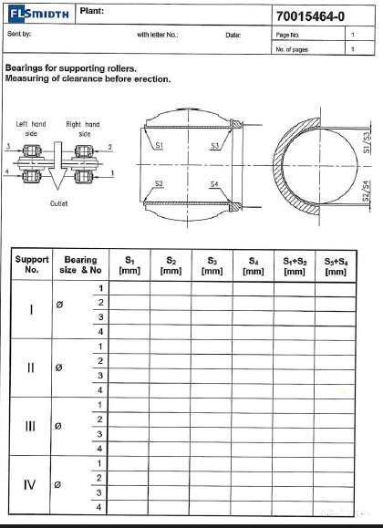
3.2.1 Measurements of bearing corner clearances S1, S2, S3 and S4
Previous to any check measurement it must be ensured that the liner and ball
socket assembly is in the right condition i.e. conforming to that shown in Fig. 3,
Appendix 9.
The bearing liner/ball socket assembly is to be suspended as shown on Fig. 4,
Appendix 1 and the bearing surfaces of liner and journal carefully cleaned. A thin
and even layer of oil-thinned dark blue marking colour is applied to the journal
throughout its entire length and extending over an area of approximately 120°.
Ensuring that the liner thrust face is turned against the support roller the bearing
liner/ball socket assembly is carefully lowered to rest upon the journal. During this
procedure any accidental touching between liner and journal along the liner’s axial
edges must be avoided. Such accidental touches may result in faulty impression of
contact.
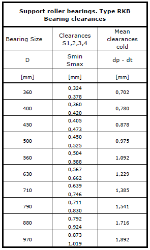
Subsequently, measurements of the corner clearances between journal and bearing
liner, S1, S2, S3 and S4, indicated in Appendix 2 are made and the recorded data
entered in the table in ref. 7. Check that the measured clearances conform to the
requirements indicated in the table, Appendix 3. In case of any deviations, FLS
must be consulted. The filled-in ref. 7 table must be forwarded to FLS together with
the erection report.
Substantial deviations must be attributable to faulty manufacture of the entire
liner- or journal geometry. Local scraping at the liner’s inlet- and/or outlet corners
is, therefore, of no effect and not allowed. Such problems must be solved in cooperation
with the responsible FLS-H specialist department.
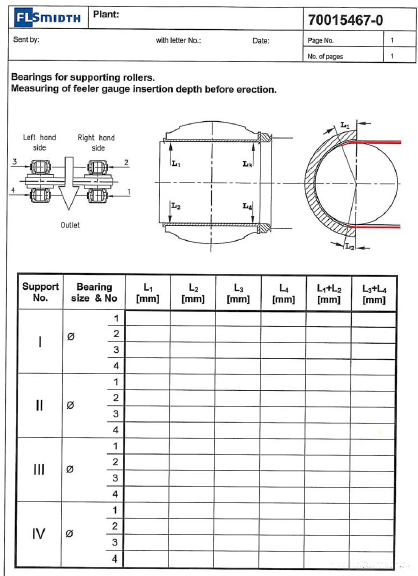
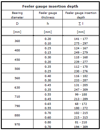
3.2.2 Feeler gauge insertion length measurements of bearing clearance
Still in this position i.e. with the bearing liner/ball socket assembly resting upon the
journal a feeler gauge of thickness as indicated in the table of Appendix 4 is inserted
as far as possible along the L1-L2 perimeter into the incoming part of the
lubrication clearance and the depth of insertion measured.
Subsequently, the same feeler gauge is inserted along the same perimeter into the
outgoing part of the lubrication clearance and the depth of insertion measured.
Finally, it is checked whether the addition of the two depths of insertion falls within
the interval given in the Appendix 5 table and the recorded data entered in the
table in ref. 8. The filled-in ref. 8 table must be forwarded to FLS together with the
erection report.
The above procedure is repeated at the L3-L4 perimeter.
3.2.3 Blue colour check on bearing clearance
A blue colour check of the bearing clearance may be carried out as a mere qualitative
supplement to the two above-mentioned quantitative check procedures. Still
with the liner resting upon the journal the liner/ball socket assembly is to be moved
back and forth a couple of times in short axial movements WITHOUT any simultaneous
rotational movements between liner and journal. Such rotational movement
will increase the seeming contact area and, consequently, contribute to a faulty
impression of the contact.
Following the above-mentioned measurements the liner/ball socket assembly is carefully lifted to check the
contact width. Again and with the same argument it is important that the lifting procedure is carried out WITHOUT any simultaneous rotational
movements between liner and journal.
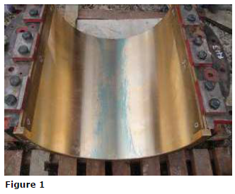
A typical and fully acceptable contact with a contact width of approximately 10-15 % of the bearing diameter is
shown at figure 1.
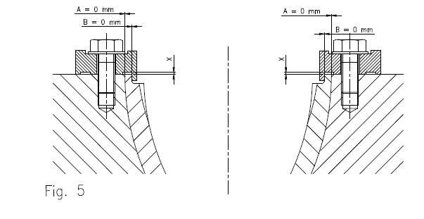
Finally and subsequent to successful measurement procedures, to allow for different thermal expansion between liner and socket, and in the above-mentioned
sequence, 6A-6F, loosen, turn and retighten the stop irons according to Fig. 5, Appendix 9.
ERECTION CHECK
If some of the measurements S1, S2, S3, S4 are ascertained to be too small, this
may be ascribable to inadequate cleaning between the bearing liner and ball race.
The bearing liner must be dismantled and surfaces between bearing liner and ball
race must be cleaned very carefully. After re-mounting the bearing liner, the inspections must be repeated.
ERECTION CHECK
Consultation with FLS is needed if deviations are found substantial.
Before the bearing liner/ball socket assembly is removed from the journal, the
latter must be match-marked with the bearing liner
.
Finally, the journal must be smeared with oil of a grade corresponding to that which
will subsequently be charged to the supporting roller bearing, thereby protecting it
against rust formations during the continued erection process.
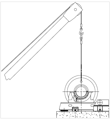
3.3 Mounting of bearings on bed-plate.
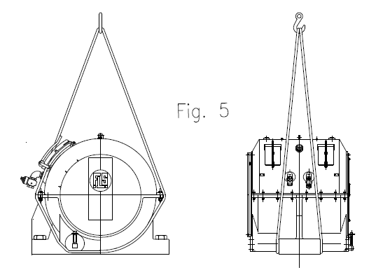
Lift the bearing housings belonging to a specific support roller, one at a time, as
shown in Fig. 5, Appendix 1 and place them on the corresponding hinged bedplates
with a distance from the centreline of the frame structure approximately 3
mm greater than that indicated on the position drawing. This allowance is required
in connection with the subsequent fine adjustment and the sequence will reduce the
period of time where the bearings are opened with risk of contamination and damage.
Dismantle and lift away the top part of the bearing housing.
To prepare for mounting the liner/ball socket assembly in the bearing housing, a
lubricant similar to that with which the bearing will subsequently be filled must be
applied to the spherical faces.
Position the bearing liner/ball socket assemblies with HORIZONTAL dividing faces
i.e. without the guide pin (7) inserted to allow for subsequent mounting of the
supporting roller, see Appendix 11.
From a position vertically above the bearing liners the supporting roller is now
lowered until the clearance between journals and liners is approximately 5 mm.
During this operation accidental contacts between journals and liners must be
carefully avoided.
The liner/ball socket assemblies are now turned 30° to their final positions and the
guide pins (7) mounted. The external plate for fixation of guide pins must be sealed
using the liquid sealing paste included in the supply and subsequently mounted.
Pour lubricant corresponding to that subsequently to be charged to the bearing
between journals and bearing liners and lower the supporting roller to its final
position.
Before continuing the erection work bearings and supporting roller must be aligned
in relation to the kiln centreline as described in instruction manual ref. 4.
3.4 Installation of lubricant tray, top part, etc.
See assembly drawing.
3.4.1 Lubricant tray (8)
Always ensure that all screws and bolts have been effectively tightened before
proceeding with the mounting of lubricant cup ring, lubricant cups and lubricant
tray. The inclination and position of the lubricant tray depends on the measurements
stipulated on the assembly drawing. Place a spirit level on top of the lubricant
tray reservoir to check that it is adjusted horizontally perpendicular to the kiln.
3.4.2 Top part (10)
Lift the top part to its proper position as soon as possible after the supporting roller
has been placed on the bearings and the oil tray has been mounted. Use the liquid
sealing paste included in the supply for sealing the joint faces between top part and
base part.
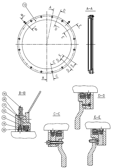
3.4.3 Seal (13)
See detailed assembly drawing and Appendix 10.
Carefully clean the supporting roller shaft at the location where the seal is to be
fitted.
Mount the innermost two-part sealing ring (14) with the joint faces horizontally.
Check that the diameter of the rubber sealing ring (15) is correct. If necessary
adjust the length of the rubber seal so that its two ends butt tightly together at the
joint.
Mount the rubber sealing ring (15) around the journal. The coil spring (16) for the
rubber seal is to be screwed together around the journal and mounted in the
groove for the rubber sealing ring. The assembly of the rubber sealing ring must
take place at the top of the bearing, approx. 100 mm from the vertical level.
Apply a generous amount of grease, mat. 7445, to the rubber sealing ring (15) and
push it to its intended position.
Mount the centremost of the two-part sealing rings (17) with vertical joint faces!
Apply a generous amount of grease, mat. 7445, to the next rubber sealing ring
(18) and to the clearance against the rubber sealing ring (15).
Mount the outermost rubber sealing ring (18). The rubber seal joint must be located
at the top. If necessary, adjust the length of the rubber seal so that its two
ends come tightly together in the joint.
Mount the last two-part sealing ring (20) with the joint faces horizontal!
Fit the grease nipples (19).
3.4.4 Lubricant sight glass (21)
See detailed assembly drawing.
Mount the lubricant sight glass (21), see Appendix 7. Check that the O-ring between
flange and base part of bearing (3) has been fitted. Check that the vent hole
(22) at the lubricant level glass top does not show signs of clogging.
Check that the drain plug (23) has been fitted and tightened.
3.4.5 Blank flange (24)
Mount the blank flange (24) nearest the supporting roller. Check that the O-ring
between flange (24) and the base part of bearing (3) has been fitted.
3.4.6 Thermal sensor (28)
Mount the thermal sensor in the bearing as shown on the assembly drawing.
Strict attention must be given to the direction of rotation. The thermal sensor must
be mounted on the “descending” side of the supporting roller shaft. It is of crucial
importance to the function of the supporting roller bearing that the thermal sensor
is mounted and connected in a correct manner so that the signals in the control
room correspond to the correct i.e. corresponding support bearing.
The clearance hole in the top part for the thermal sensor signal cables must be
sealed with silicone to prevent ingress of water and dust into the bearing housing.
MANDATORY
The kiln must not be started until all thermal sensors have been fitted and made
operational!
3.4.7 Inspection ports (25)
Adequate measures must be taken to ensure that the inspection ports cannot be
opened by unauthorized persons during the ensuing erection process.
The protective grating (26) under the inspection ports is secured by means of a
screw (27). If the screw is dismantled, it will be necessary to check that it has been
e-fitted prior to start-up.
3.5 Mounting of accessories for cooling system
See assembly drawing and arrangement drawing.
The bearing cooling system may be a closed system with recirculation of the cooling
agent (glycol/water), or it may be an open system, with discharge of cooling water
to a sewer.
Pipes, three-way cock (31), flow indicator (30) etc. must be mounted according to
the assembly drawing.
Prior to mounting all threads must be packed with packing yard and sealing paste
must be applied to the threads. Use of Teflon tape as packing is NOT advised due to
the higher risk of leaks developing in this type of packing.
The first time cooling agent is applied to the system, a leakage test of the system
must be carried out. Particular attention must be given to the joint between the ball
socket and the lead-through pipes.
If mounting is carried out at location where temperatures below the freezing point
may occur, adequate measures must be taken to prevent severe damage to the
system due to frost action.
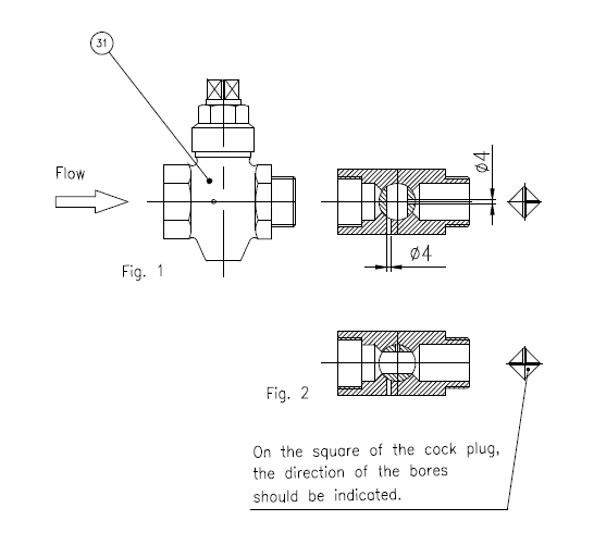
The three-way cock (31) at water supply point is equipped with a vent hole which is
to be used for draining the water in the cooling water system. It must be checked
that this vent hole has been drilled in the three-way cock, and that the cock has
been correctly fitted, see Appendix 12.
3.6 Lubrication during erection and start-up
The bearing must be charged with lubricant corresponding to the grade specified in
lubrication chart immediately after completion of the installation and the seals must
be greased by mat. 7445.
Lubricant volume for each bearing size:
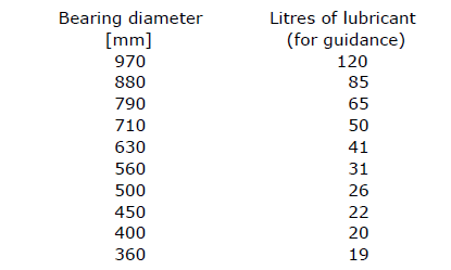
Note
-Lubricant must not be filled beyond the upper mark on the oil level glass since an
excessive amount cause oil spillage.
The lubricant level must be re-checked after rotation of the kiln for the first time.
The lubricant cups (9) have now been filled, and, therefore, the level has dropped.
If necessary lubricant must be refilled
3.7 Lubricant quality
The different lubricant types are in the following designated according to FLS
Symbols to Lubricants.
The selection of lubricant type depends on the ambient temperature.
For kiln start-up and operation at ambient temperatures lower than +5°C, lubricants
with FLS symbol Mat 7156 (EP460) or Mat 7157 (EP680) must be applied.
Polyalphaolephines which have low pour points and are mixable with mineral oil is
considered the best approach here.
Polyglycols are NOT to be used since they may dissolve the paint inside the bearing
and damage the seals!
For kiln start-up and operation at ambient temperatures higher than +5°C, lubricant
with FLS symbol Mat 7157 (EP680) or Mat 7158 (EP1000) must be applied.
These lubricant grades must be applied during the running-in phase – regardless of
any objections from client or lubrication experts.
3.8 Inspection of supporting roller shafts (4)
During the erection process it must be checked at regular intervals that the supporting
roller shafts in all bearings are covered by rust protecting oil film.
3.9 Turning of kiln
Before turning of the kiln and prior to every start-up lubricant of the specified grade
must be poured over all supporting roller shafts to ensure effective lubrication of
the bearing liners.
Note!
In an abnormal situation with the bearing temperature rising to above 65°C and
where attempts to reduce the temperature level have been unsuccessful it may be
fruitful/necessary to switch to a higher grade lubricant e.g. from EP 680 to EP 1000.
In extreme situations, the Mobilgear SHC-3200 with a base oil viscosity of 3200 cSt
can be used in trouble-shooting.
3.10 Grease Quality
A grease quality with FLS symbol Mat. 7445 must be used for the bearing seals.
Reference is also made to instruction manual, ref. 6
3.11 Mounting of heat shields
Large hear shields for protection of personnel and equipment are used on some kiln
supports. If this is not the case, smaller heat shields (34) must be mounted to
protect the bearings against radiant heat from the kiln. A loose protection plate
(35) must be mounted between the heat shields for the two bearings.
Regardless of the heat shield applied, the heat shield on the descending side of the
kiln must be equipped with an arrow-shaped guide plate to prevent any falling
objects from the kiln from being trapped between the supporting roller and kiln
tyre.
See separate assembly drawing.
4.0 Operation & maintenance
4.1 Lockout procedure for maintenance
See separate instruction manual for operation and maintenance, ref. 6.
5.0 Key to appendices
(1) Ball socket, Bearing shell
(2) Bearing liner
(3) Base part, bearing housing
(4) Supporting roller shaft
(5) Thrust ring
(6) Stop iron
(7) Guide pin
(8) Lubricant tray
(9) Lubricant cup
(10) Top part
(11) End cover
(12) Air filter
(13) Seal
(14) Sealing ring
(15) Rubber sealing ring
(16) Coil spring
(17) Sealing ring
(18) Rubber sealing ring
(19) Grease nipple
(20) Sealing ring
(21) Lubricant sight glass
(22) Venting
(23) Drain plug
(24) Blank flange
(25) Inspection port
(26) Protective grating
(27) Screw for protective grating
(28) Thermal sensor
(29) Rubber bushing
(30) Flow indicator
(31) Three-way cock
(32) Bolt
(33) Guide block
(34) Heat shield
(35) Heat shield
(36) Adjusting screw
(37) Block for adjusting screw
Appendix 1 – Sketches of bearing, ball race and bearing liner
Appendix 2 – Measurements of bearing corner clearances
Appendix 3 – Table of measurement of bearing corner clearances
Appendix 4 – Feeler gauge insertion length measurements
Appendix 5 – Table of feeler gauge insertion depth measurements
Appendix 6 – Longitudinal cross-section of bearing
Appendix 7 – Bearing
Appendix 8 – Axial cross-section of bearing
Appendix 9 – Fixation of bearing liner
Appendix 10 – Seal at support roller
Appendix 11 – Lifting the support roller
Appendix 12 – Three-way cock