Contents
EVERYTHING YOU NEED TO KNOW ABOUT CEMENT KILN ERECTION | MASTER THIS POST AND YOU WILL GET PAID 75K USD/DAY
[wpecpp name=”package + Updates forever” price=”250″ align=”center”]
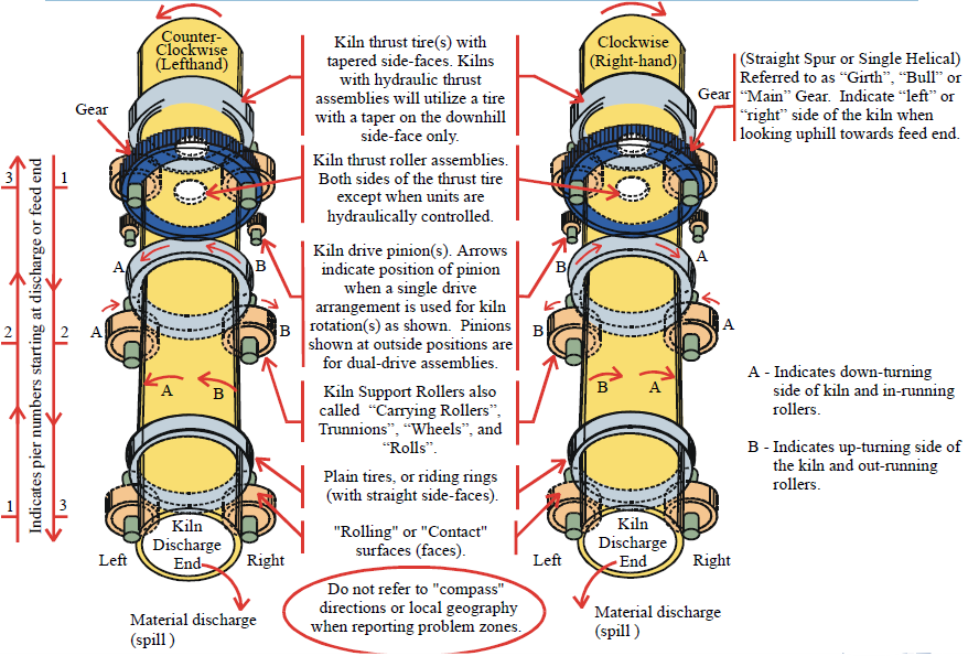
Orientation & Common Terminology for Reporting Kiln Details
Feed End of Kiln(s) (Also referred to as “Uphill” or “High-End” Area)
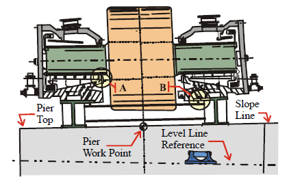
Kiln Support Frame Setting Reference
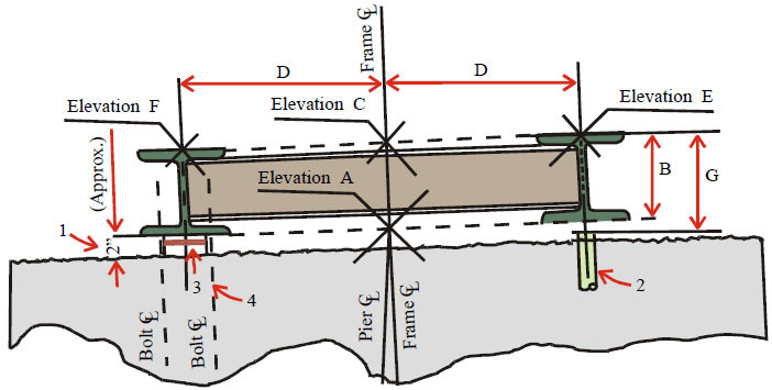
1 – 2” Allowance for grout between frame and rough pier top.
2 – Elevation reference plug. Set in pier on beam-web CL. Locate plug 6” outward from end of beam.
3 – 5” long shims. (Refer to kiln installation instructions).
4 – Anchor bolts added to prevent “rolling” of beams.
Refer to foundation drawing and roller assembly drawings for elevations, frame dimensions and slope of the kiln.
A – Reference elevation for support assembly.
B – Frame height (may vary after machining, use design dimension for calculation of top surface elevations).
C – Elevation A plus dimension B. (Not for actual test work).
D – Calculate rise or drop from frame CL to high or low beam CL to su it designed slope of equipment.
E – Elevation = C plus rise for D.
F – Elevation = C minus drop for D.
Carefully check and record elevation at top of plug.
F = Required elevation at CL on m achined t op s urface o f b eam m inus reference plus elevation.
Use dimension G for setting elevation of control beam. Use precision straightedge with slope test block and machinists
level or inclinometer for follow-up slope adjustment of the frame.
Kiln Support Frame Adjustment and Tests
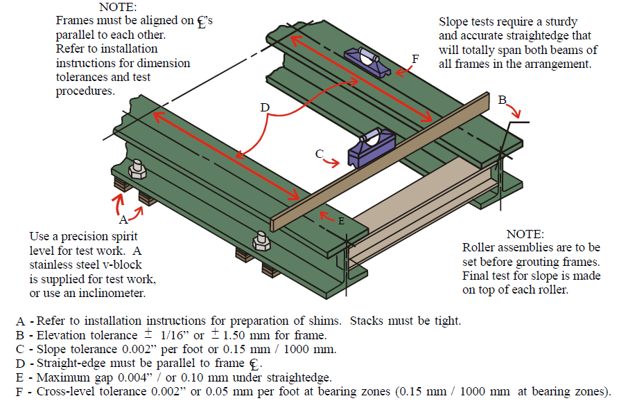
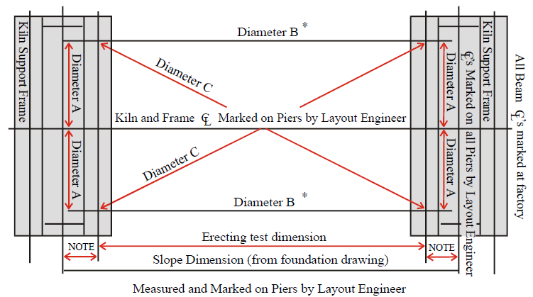
Kiln Support Frame Spacing Test Points
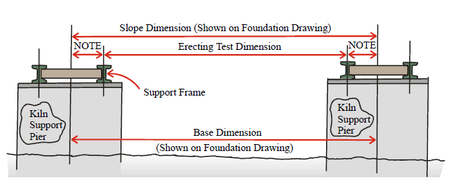
NOTE: “Support Roller Assembly” drawing numbers for each pier are shown on the “Foundation” drawing. Refer to the correct drawings for piers being checked. These drawings show the dimension from frame CL to beam CL for each assembly
Add half-frame dimensions for piers being checked and subtract total from slope dimensions shown on foundation
drawing to obtain test dimension (as shown above in sketch).
Use spring scale to apply 20 to 25 lb’s or 9 – 12 kg. tension to tape line (depending upon wind conditions).
Check tape line temperature and make allowances for possible variation for dimension being checked.
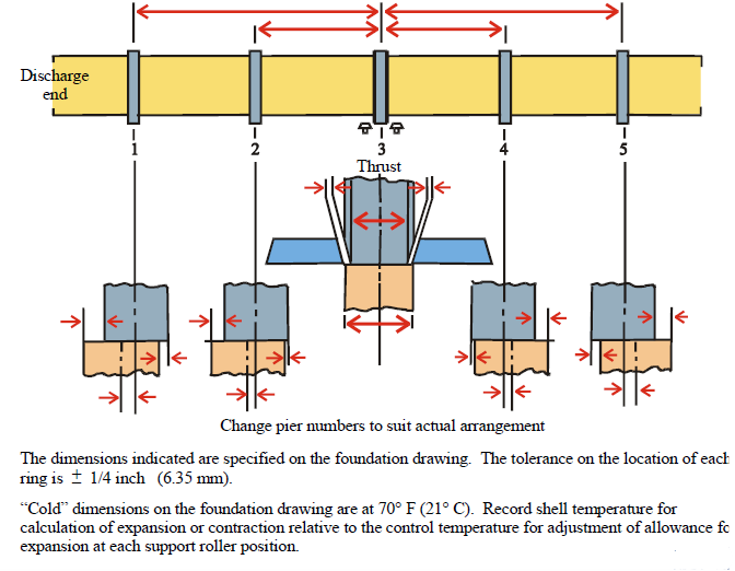
Kiln Support Frames Spacing, CL & Parallelism Tests
Testing New Kiln Support Roller Installations, or Re-Aligning Older Equipment
Recommended Water Piping Arrangement for Kiln Support Roller Assemblies
A – Roller adjusting assembly. Keep these zones open for roller re-setting work.
B – Flexible lines to allow for possible 4” to 5” or 100 mm to 150 mm movement.
C – Inlet water master value.
D – Control value at inlet line to each water jacket.
E – Funnel arrangement for drain lines.
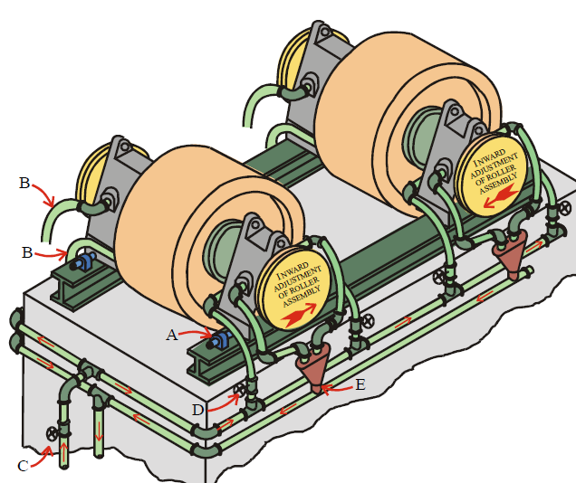
NOTE Keep lines clear of end plates to allow for bearing inspection and maintenance work.
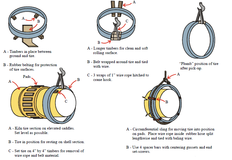
Handling Kiln Tires for Installation on Pads with Slide Bar Arrangement
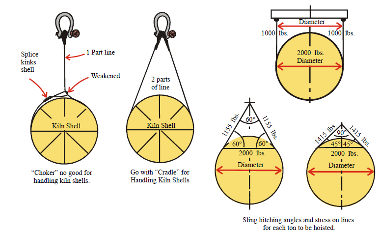
Crane Hitch Arrangements for Handling Kiln Shell Sections (Off-Loading and at Assembly Area)

Crane Hitching for Kiln Shell Sections Hitch Angles and Stress on Lines
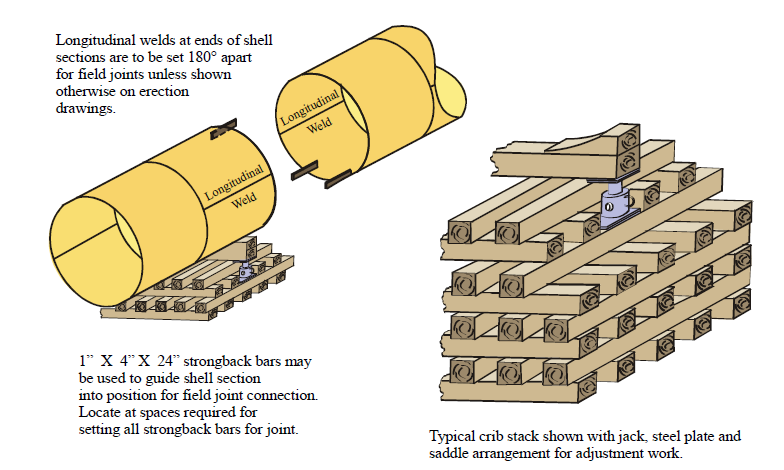
Kiln Shell Support
Alignment Fittings
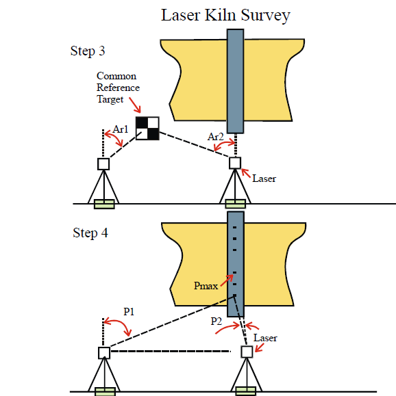
Checking Alignment
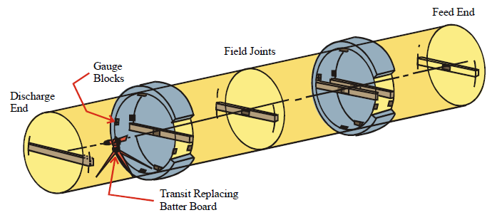
Tumble or rotate instrument 180° for test at discharge end target.
Instrument cross-hairs or center of a laser beam must be within 3/32” or 2.5 mm of target center at all
test positions.
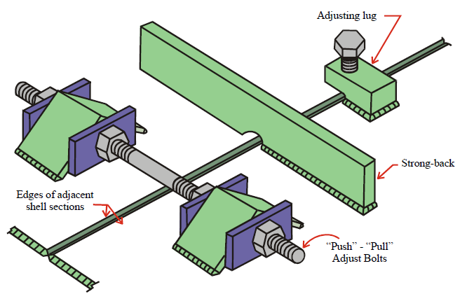
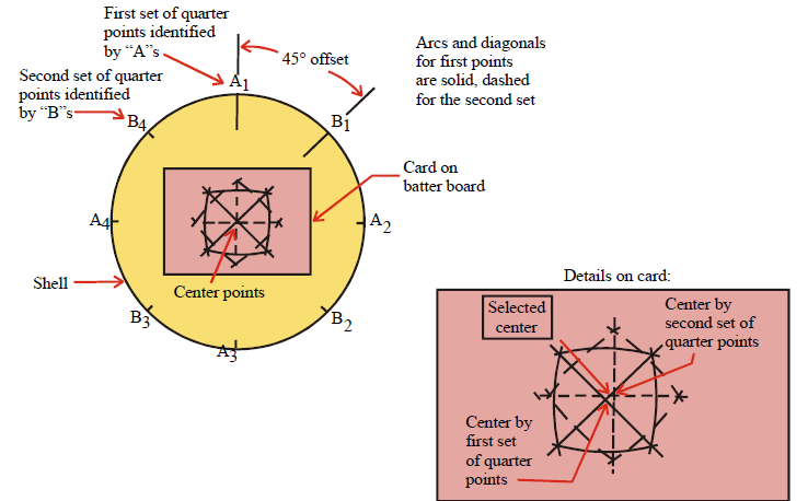
Kiln Shell Alignment Test Batter Boards
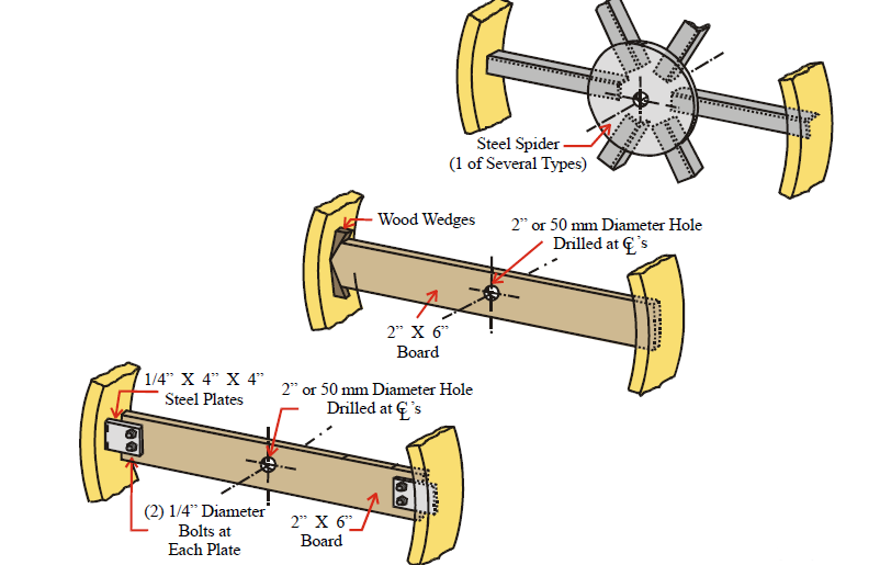
Kiln Alignment Target and Layout Trammel
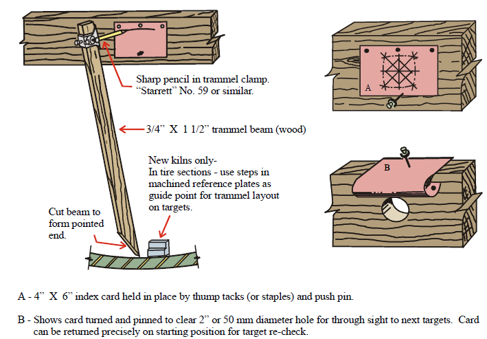
Locating the Center of the Shell
Kiln Shell Section Alignment Tests (Alternate Arrangement)
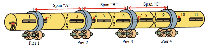
After aligning and tack-welding span “A”, as for 2-section 2-support kiln (figure kiln overhead 014.cdr) or when this length
has been factory built, alignment of following spans can usually be achieved by adjusting support rollers.
Usually completion of joint in span “A” will eliminate need for support at joints in following spans. Actual support
requirements will depend on section design for shipping.
Actual sequence of installation and alignment must be determined on-site to suit actual number of shipping sections
For Alignment of Kiln with Sections as Shown Above
Finish span “A” as in test for 2-section, 2-support kiln (shown in figure kiln overhead 014.cdr).
Set transit on kiln axis. Lock on target 5. Cross-check on targets 4, 3, 2, 1.
Lock transit on target 8. Back-check on 7, 6, 5, 4, 3, 2, 1. Adjust rollers, if necessary, to bring line of site within 3/32” or
2.50 mm of target centers.
Lock transit on target 11. Back-check on 10, 9, 8, 7, 6, 5, 4, 3, 2, 1. Adjust rollers, if necessary, to bring line of sight within
3/32” or 2.50 mm of target centers.
Minor errors on short fore-sight will “grow” on each following target. Avoid errors, save time and avoid confusion by
working from most-distant far-sight.
Kiln Shell Field Joint Bracing and Tack Welding
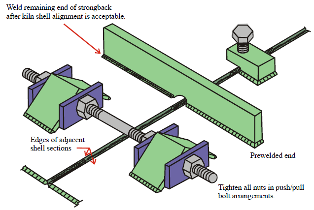
Tack weld in bevels, at least 6” or 150 mm long, at fixtures used for alignment of adjacent plates.
Deposit root weld bead.
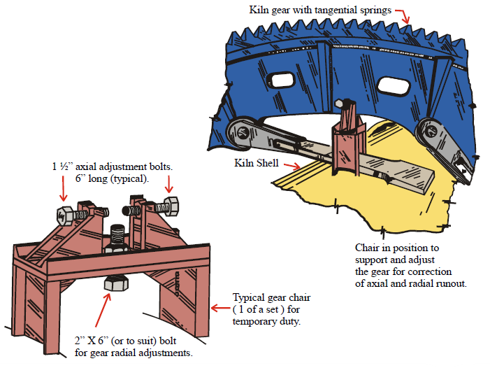
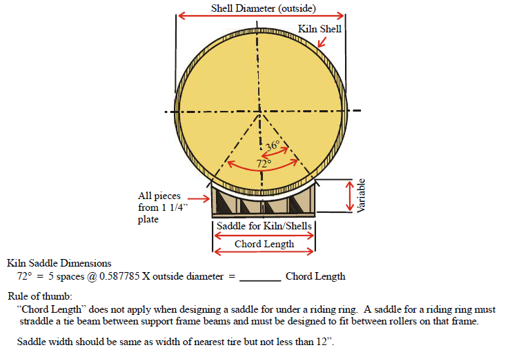
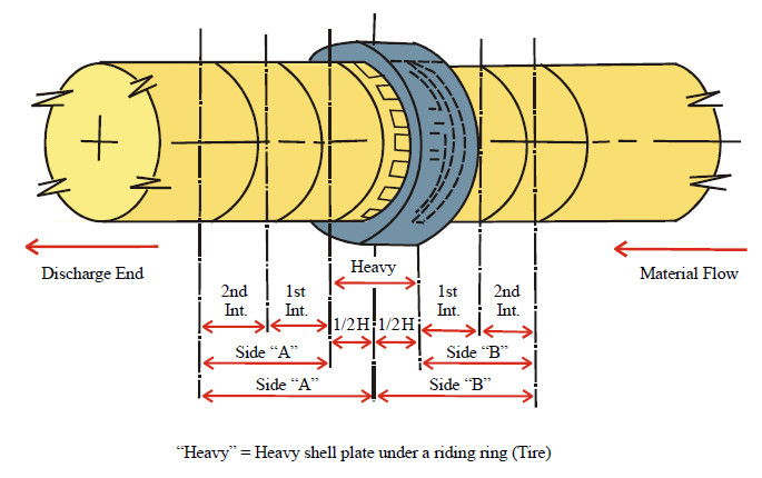
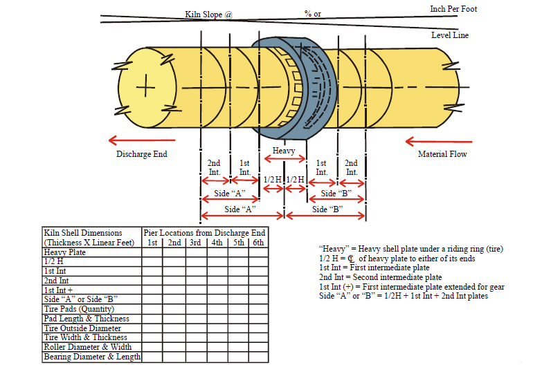
Riding Ring Location
Temporary Support Chair for a Kiln Spring Gear
Gear Guard and Splash Band Assembly
A – Gear guard section
B – Flange joint for removable panel
C – Splash band sections
D – Spring plate for gear
E – Kiln shell plate
F – Spacer guides
Splash band installation notes:
1 – Prepare and install spacer guides.
2 – Install segments with care.
3 – Align and tighten flange joints.
4 – Align and tach weld panel butt joints.
5 – Verify straightness and clearance all
around.
6 – Weld flanges to shell. Must be oil tight.
7 – Remove scraps. Clean off weld spatter.
NOTE:
If conduit must pass through bands to reach a thermocouple, install before guard assembly work
Kiln Support Roller Adjustment and Testing
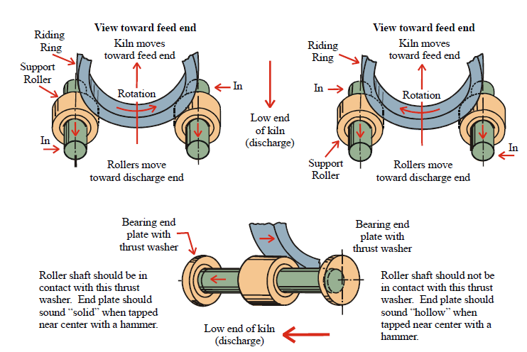
Skewing Rollers
Ideal Roller Skewing:
All rollers should be pushing uphill slightly or neutral.
With a two thrust roller system (as here) the kiln should be floating between the thrust rollers.
With a one thrust roller system there should always be contact between thrust roller and tire pressure
200-800 psi or 15 to 60 bar.
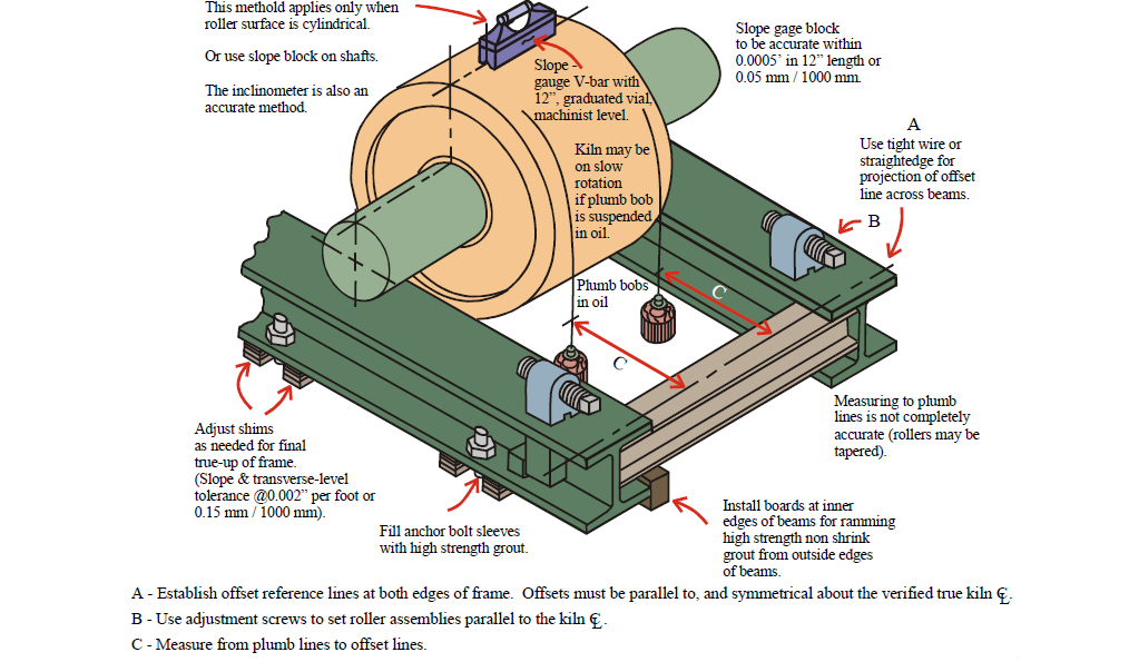
Support Roller Assembly Alignment Control
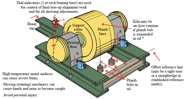
A – Scribe beam surface at edge of bearing base to establish reference points for measuring bearing movement during
the roller relocation work period.
B – If it is possible to work simultaneously at both bearing positions, use 2 plumb lines for measuring movement.
*- This procedure is not valid if the roller is cone shaped or distorted on the rolling contact surface.
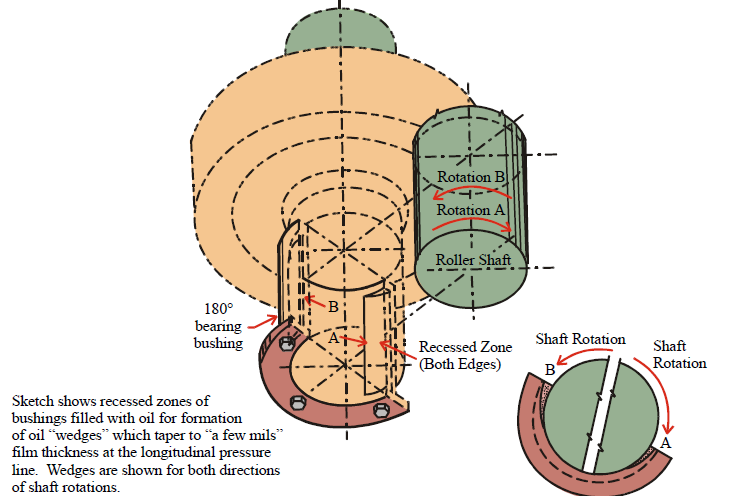
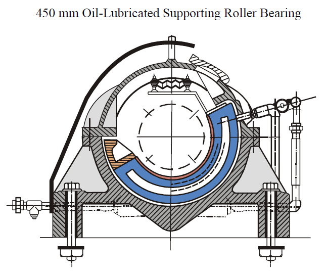
Kiln Support Roller Bearing Bushing Lubrication
Temporary Kiln Support Jacking Kiln Shell to Unload Support Rollers
Jacking Kiln Shell to Unload Support Rollers
Jacking Kiln Tire to Unload Support Rollers
Refer to the foundation drawing for the kiln for the pier loading figure at the tire to be raised;
jacking capacity for that area will be indicated by the vertical load shown for that pier.
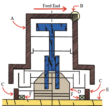
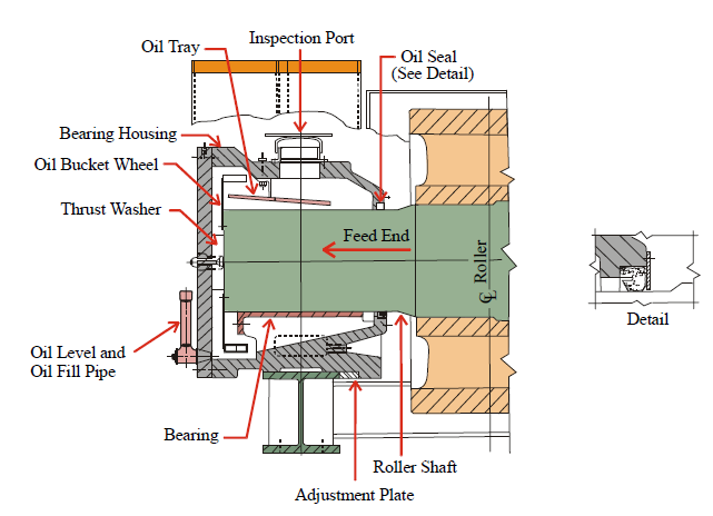
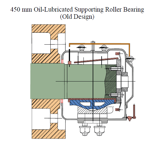
Familiarization Kiln Support Roller Bearing Oil Level and Leakage
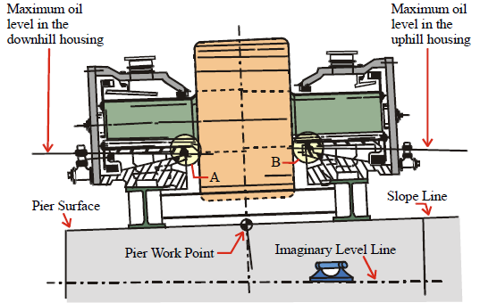
A – No oil leaks at downhill shaft seal except when overfilled, dirt and rainwater enter housing when seal is bad, as
when a liner is badly damaged.
B – Shaft seals are not dams. Oil level must not reach seals at uphill bearing assemblies.
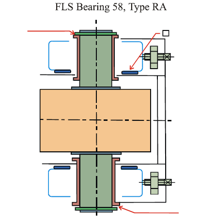
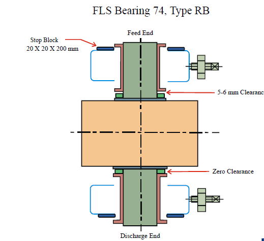
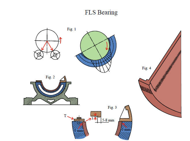
Self Aligning Ball and Socket Type Bearing FLS “58”
“Type RA” Design Bearing
Kiln Support Roller Adjustment and Testing
Kiln Support Roller Skewing Roller Adjustment Rule of Thumb
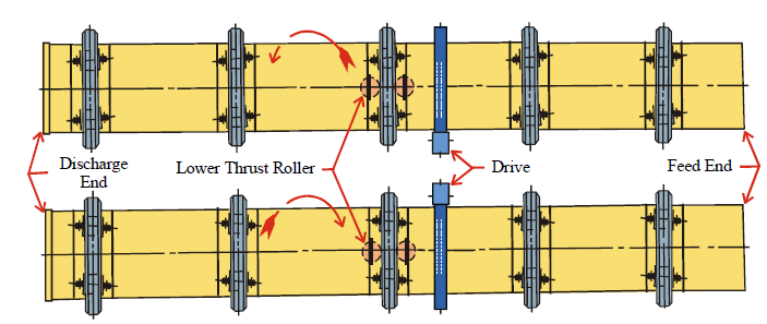
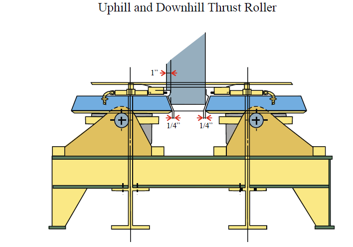
Normal Offset Position of Thrust Rollers
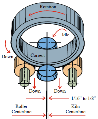
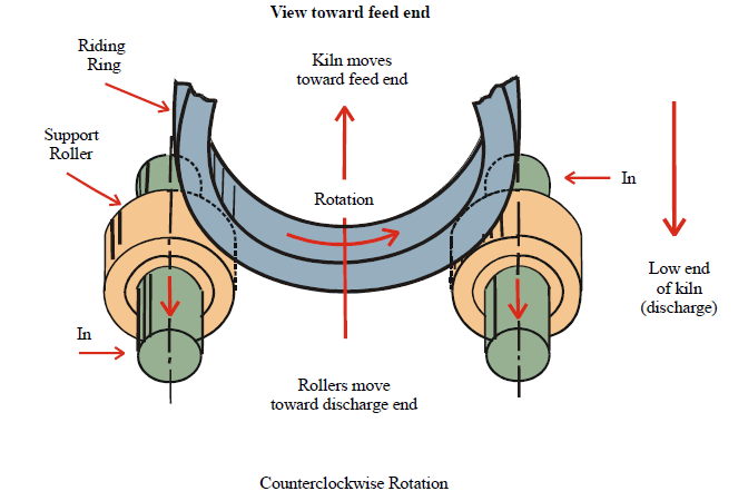
Thrust rollers must be offset from the true frame longitudinal centerline toward the down – turning side of the kiln
for normal (safe) operation
Wrong Offset Position of Thrust Rollers
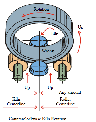
Thrust rollers will rise, or try to rise, out of their bearing bases when their centerlines cross over the true
frame centerline toward the up-turning side of the kiln, and when the kiln shifts toward its own downturning
side.
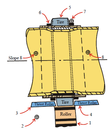
Plain Roller Support Assembly
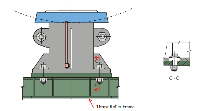
Thrust Roller Assembly Two Thrust Roller System
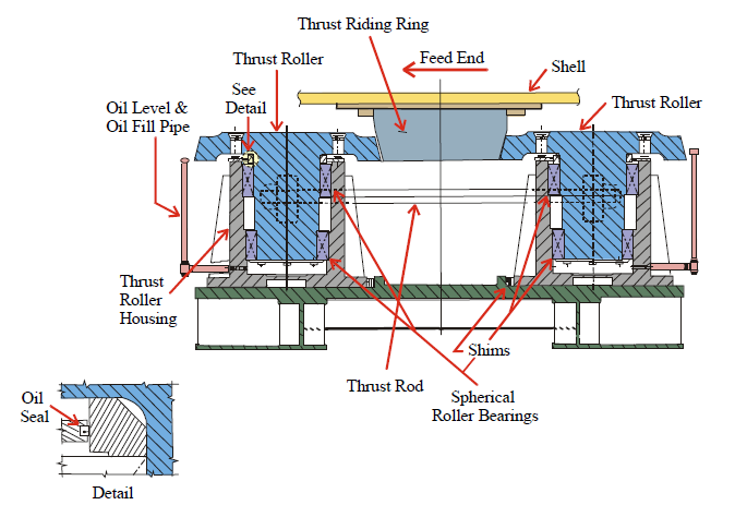
Thrust Roller Assembly
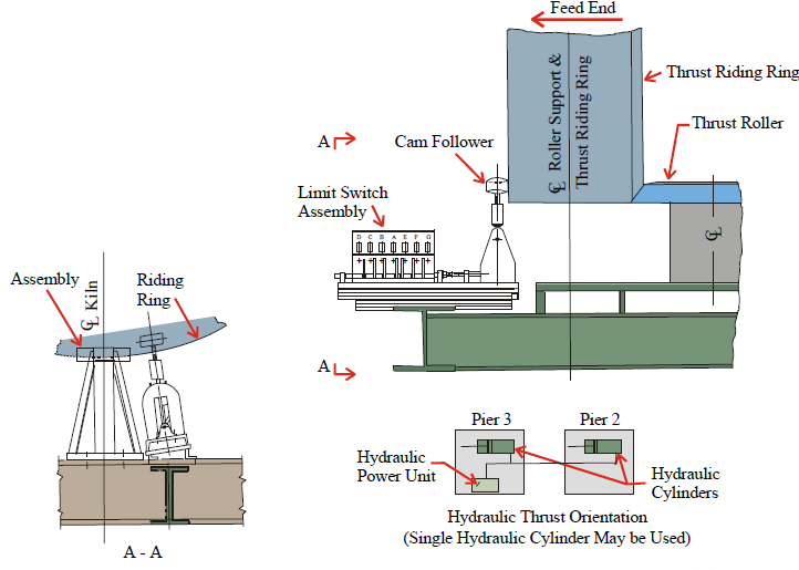
Hydraulic Thrust Roller Assembly
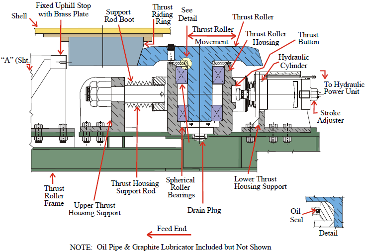
Hydraulic Thrust Roller Assembly
Operation of Limit Switches
A – Stops Hydraulic Pump Set
B – Pressure in System Relieved
C – Sounds Alarm
D – Shuts Kiln Drive Down
E – Starts Hydraulic Pump Set
F – Sounds Alarm
G – Shuts Kiln Drive Down
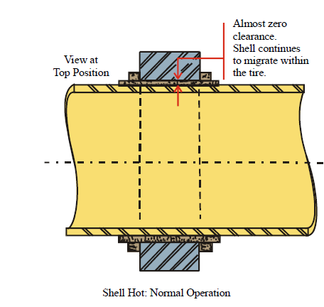
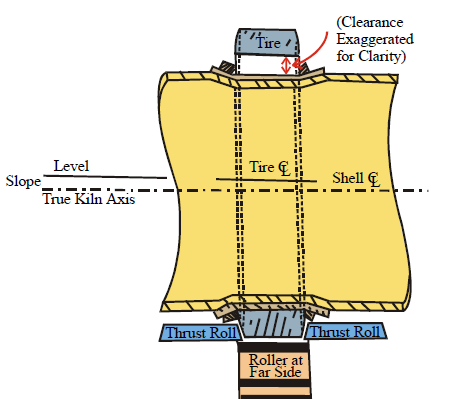
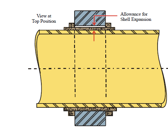
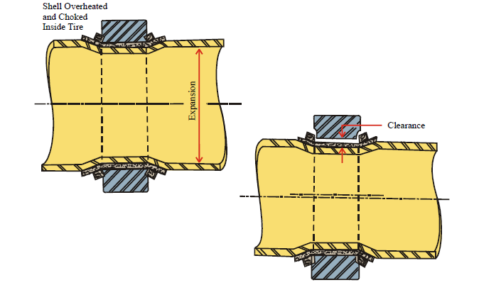
Routine Checkout at Kiln Tire Sections
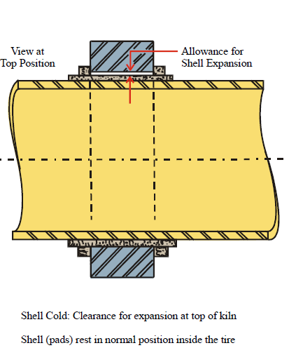
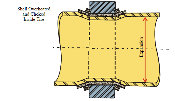
Shell overheated and choked inside tire. Shell expands proportional to internal heat, but must bend at sides of tire.
Tire retainers on bend pads bite into the tire, tire and retainers become worn. When shell temperature returns to
normal, shell pad to tire clearance is excessive.
No shell migration may eventually be followed by permanent kiln shell choke-down deformation.
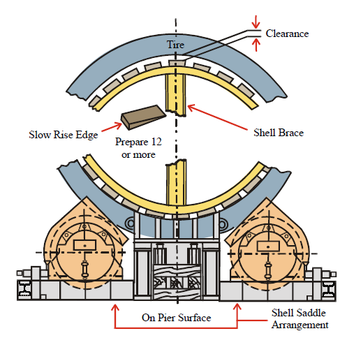
Field Installation of Kiln Tire Section Spider Bracing
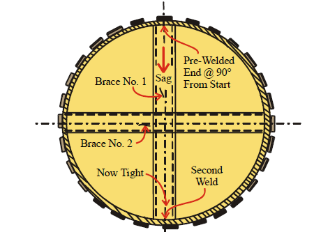
When the pre-welded end of Brace No. 1 is at the top of the shell after 90° of rotation, shell sag moves the loose
end against the bottom of the shell and in position for welding.
Brace No. 2, and possibly No.’s 3 and 4, will be needed for pad replacement work requiring frequent rotation
of the shell.
Spider bracing is for holding the shell as round as possible for pad replacement work. Before welding bracing
to the shell, verify roundness by using trammel layout work for marking the shell axis on Brace No. 1 to establish
a reference point for radius measurements.
Routine Checkout at Kiln Tire Sections
Check (frequently) each tire section in the kiln arrangement. When shell migration in not recorded, the kiln shell
is very near the point of serious deformation damage plus shell and refractory breakdown problems.
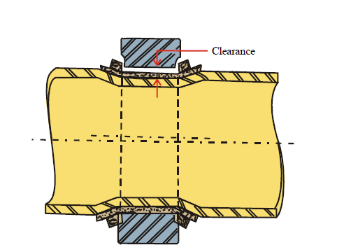
When normal coating builds up on refractory, the main shell returns to normal diameter but the permanently
deformed tire section shell is small in relation to the tire bore diameter.
With the tire in a normal alignment position the kiln shell is misaligned at the low-riding deformation zone.
Excessive down tire follows choke-down deformation.
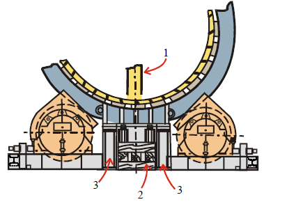
Field Installation of Kiln Tire Section Spider Bracing
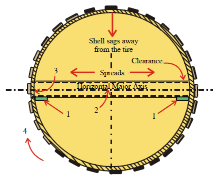
1 – Install support plates at both sides of the shell.
2 – Lift bracing leg onto support plates. Check squareness.
3 – Hold end of brace against the shell for welding.
4 – Rotate shell 90° to place weld at top center position
Field Installation of Kiln Tire Section Spider Bracing
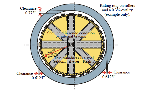
New measurement problems must be considered when/if internal bracing holds the shell in a perfectly round condition.
If the riding ring rests on support rollers, ovality will not have changed; now measurements will be between a round
shell and an oval riding ring.
When the riding ring is on the support rollers, and the kiln shell is round (after bracing), measure clearances at both
sides at the horizontal centerline, and at top-dead-center between shell pads and the riding ring bore surface. Add
dimensions recorded for these three check points, then divide the total by two to determine the actual diameter for
shell pads and riding ring bore.
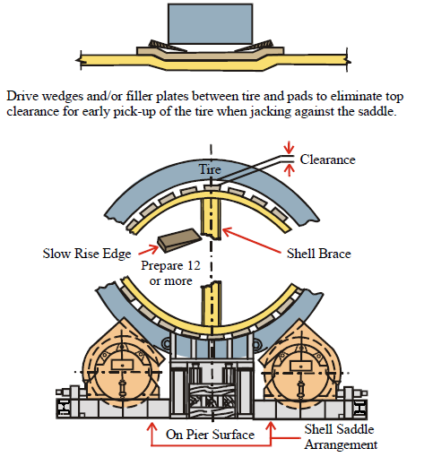
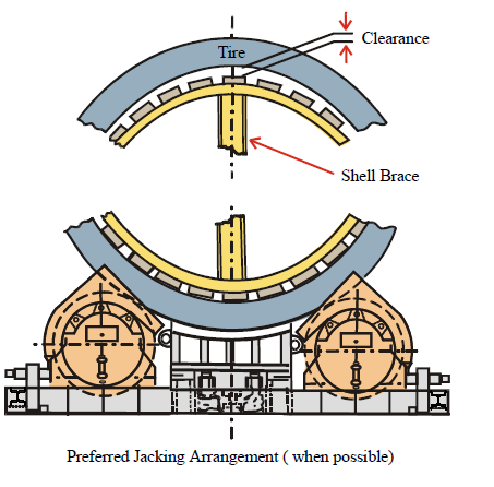
Jacking a Kiln Shell to Unload Support Rollers
Clearance between the tire and pads at the top of the shell is usually overlooked when all other details have been
considered in arrangements for jacking up the kiln shell to take a tire off the support rollers for maintenance work
on the roller assemblies in position on the support frame, or for lifting out one or both assemblies for work at ground
level or in the maintenance shop.
Jacking a Kiln Shell to Unload Support Rollers
By the time the upper pads touch the tire jacks are fighting all shell weight to adjacent tire sections.
Two to four times the jacking capacity anticipated for lifting the shell will be required if tire to pad clearance is
not considered (especially when excessive).
Excessive pad to tire clearance is a handicap for jacking up kiln shell.
NOTE: The tire will not rise until top area clearance is eliminated by the rising shell.
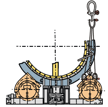
Typical Procedure for Removing Roller Assemblies from the Support Frame
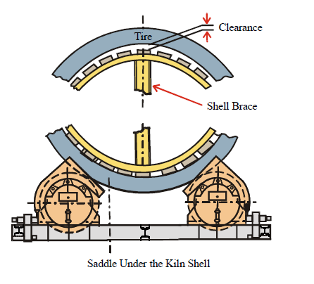
1 – Spider bracing (installed before locking out the kiln drive system, including the auxiliary drive arrangement).
2 – Timber cribbing stack with hydraulic jacks in place under steel saddle. Saddle and jack arrangement must raise
the kiln shell just enough ( 1/32”, 1 mm, or less ) to be fully loaded for removal of both roller assemblies. *
3 – Install steel or hardwood columns for security of the temporary support arrangement during the pad removal and
replacement work period.
* – If the tire is rising with the shell. If clearance between the tire and shell pads was not accounted for, excessive
jacking will be required to lift the tire away from the support rollers.
Typical Procedure for Removing Fuller/Traylor Roller Assemblies from the Support Frame
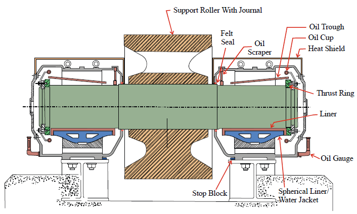
“Cutaway” view of roller assembly bearing bases shows internal arrangement of components with critical clearances.
Whenever roller and bearings are to be lifted as a complete assembly, hitching arrangements must hold bearings in
full-line contact with shafts, and with no contact at shaft seal zones.
A – Remove shaft seals. Insert wood or rubber wedges between shaft and seal inset in housing. Secure these wedges
with at least one wrap of duct tape (or similar material).
B – Edges of frame beams have machined insets for control of shaft clearance between bearing end plates. Key bars
at bottom positions on housings hold bearing housings in position against machined edges for operation of the
assembly. One or both keybars must be removed to avoid interference when the complete roller assembly is
moved toward the outside end of the support frame.
Prepare hitching material similar to the arrangement shown in these sketch sheets. Distance between connecting
points must place the crane hook, spreader bar and shackles far enough above the kiln horizontal centerline for
flexibility in the lines for lift-out maneuvering.
Remove all cooling water input and drain pipes from bearing bases. Remove bearing adjustment lug and screw
combinations from frame beams. Prepare beam surfaces for outward travel of the roller assembly.
Jack or pull the assembly outward on the frame until motion is stopped by roller contact against the tie-beam at the
end of the frame.
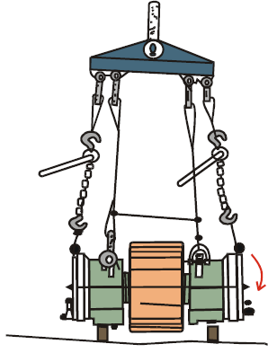
Place timbers at the ground level work area for support of the assembly with the roller off the ground The low-end
bearing housing will touch down, and hitching will become loose, before the other bearing housing rests on its own
support timbers.
Move the roller into its realignment position and into a load carrying condition. Reassemble all pipe fittings, guards
and other items which may have been removed for crane handling maneuvers. If internal fittings had not been
reinstalled at ground level, remove end plates for final fit-up work. Re-fill bearing lubricant reservoirs. Remove
pedestals, jacks, saddle and cribbing.
New Pads for Choked-Down Tire Sections
Align the kiln shell before shutting down for repair work. Cold-condition external alignment procedures are not
acceptable unless excess clearance and other deviations are accounted for. Kiln shell section alignment is critical
at all tire positions, alignment of tires is not necessarily kiln shell section alignment.
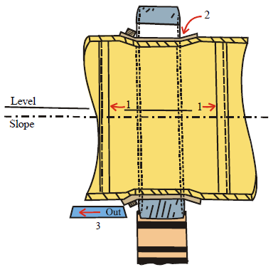
Preparation:
1 – Install spider bracing. (See bracing installation procedure on other sheets). Bracing must be installed before the
kiln auxiliary drive system is secured, along with the main drive motor, to prevent accidental rotation during the
repair work period.
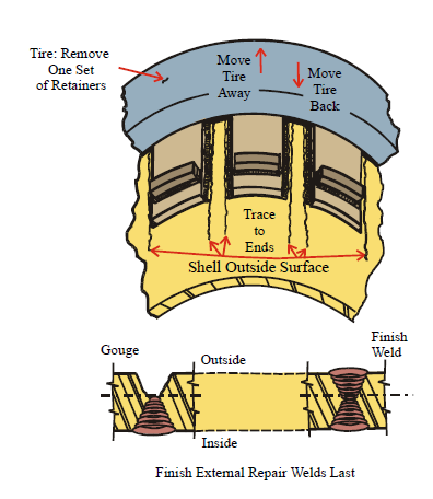
2 – Remove retainers at the side of the tire toward the direction of movement away from pads. Grind off weld scraps.
3 – Remove thrust roller assemblies.
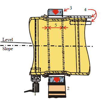
Preparation:
1 – Install steel saddle and two (or more) hydraulic jacks in a convenient location that will not interfere with work.
2 – Back support rollers away from the frame center line to let the tire move downward.
3 – As rollers move outward, check tire to shell clearance all around. Stop roller adjustment work when the tire is
in balanced position around the shell.
4 – Install skid bars at the top of the shell. Use shims for adjusting bar height for smooth movement of the tire.
5 – Mark the shell to indicate original position of tire.
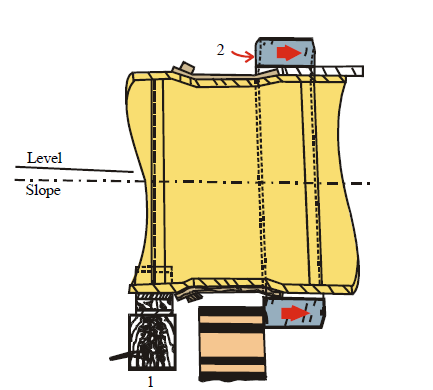
Preparation:
1 – Install a tight arrangement of steel or hardwood pedestals between the support surface and saddle.
2 – Start to jack or tug the tire off pads and onto skid bars.
Preparation:
1 – Move the tire far enough onto skid bars to allow for installation of new extra long pad plates.
2 – The bottom of the tire will swing toward a “plumbed” position if not restrained. Install gusset plates at the
bottom of the shell to hold the tire away from the pad zone.
3 – Remove both roller assemblies for free access to the shell.
4 – Start pad removal work.
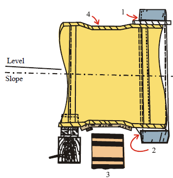
Preparation:
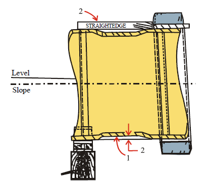
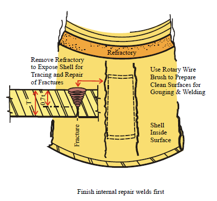
1 – Finish pad removal work. Grind down weld scraps. Remove caked dirt, rust and oil from the shell at the pad zone.
2 – Use a straightedge or a tight line for measurement from undamaged shell surfaces to the top of the depressed shell.
Measure at several points around the shell for a realistic approach for planning and preparing filler material.
The depressed zone must be filled for support of new pads. Any unfilled space, however small it may be, will allow
new pads to bend to fill the spaces as soon as rotation starts after the kiln is returned to the production department.
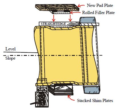
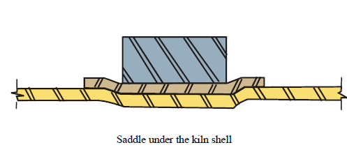
A “typical”, but unsatisfactory shim stack arrangement for filling spaces between shell and pads is shown at the
bottom of the shell. Since “all-position” fit-up work is necessary, shim stack installation is tedious (and frustrating)
work. Shim stacks are rarely, if ever, tight enough to prevent pad distortion when the work is called “finished”.
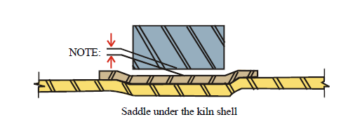
A more acceptable filler arrangement is shown at top of the shell, a rolled plate, at a thickness determined by prior
measurement, is used with appropriate thickness-adjustment shims for a more secure packing arrangement. In this
arrangement filler plates are welded to pad plates, not to the shell.
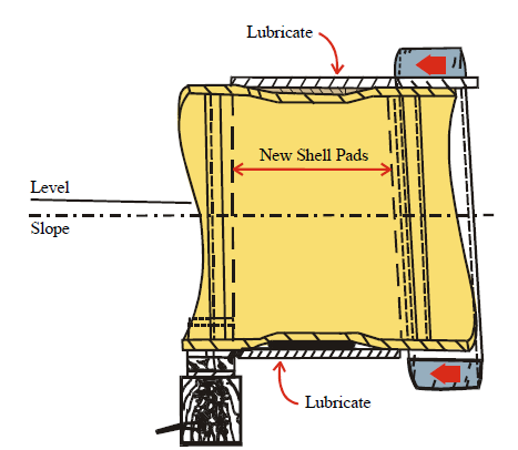
When new pad plates, with fillers, are secure around the shell, lubricate surfaces to facilitate movement of the
entire to the predetermined operating position for that particular tire.
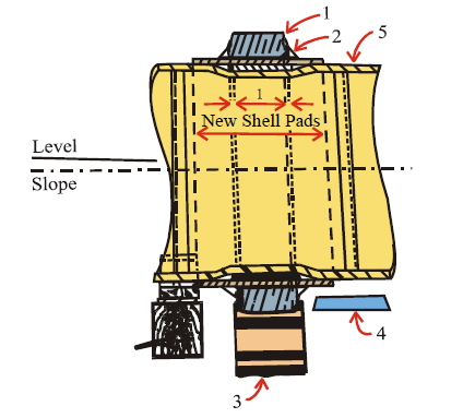
1 – Adjust tire position in relation to original reference lines.
2 – Install temporary gusset plates to lock the tire for rotation.
3 – Return support rollers to positions on the frame. Adjust for recalculated set points which consider new
conditions at the tire.
4 – Move the thrust roller into position at the clear area.
1 – Be sure that rollers are carrying the load of tire and shell.
2 – Remove pedestals, jacks and saddle.
3 – Reset thrust roller assembly.
4 – Adjust thrust roller assemblies for proper clearance in
relation to the tire and in relation to support roller
centerlines.
5 – Kiln rotation is required for testing for tire wobble.
6 – After tire wobble has been eliminated, install tire retainers.
7 – Remove temporary tire-locking gusset plates.
8 – Remove internal spider bracing. Grind down weld scraps.
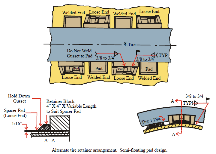
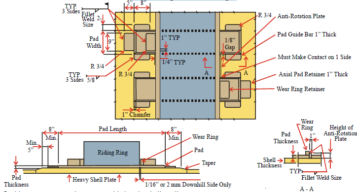
Floating Pad Design
In this arrangement pads are not welded to the shell at all.
The shop installed cost for this arrangement is high, but the future field replacement of pads is simpler and less
expensive.
The continuous wear rings installed between the riding ring end faces and wear ring retainers reduces bearing pressure
and gouging in the riding ring end faces and also increase wear life of the components.
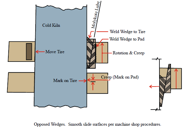
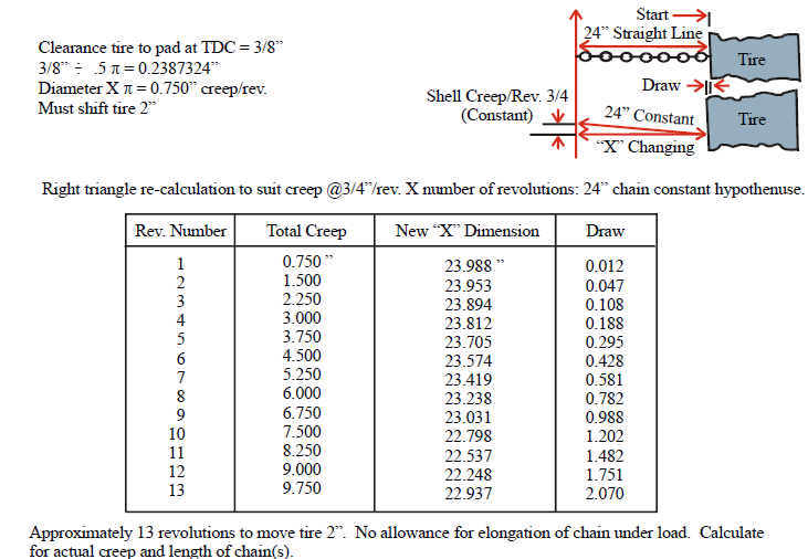
It is very easy to reduce tire creep: Install shims between shell and pads and tack weld new shims to pads
Using Wedges for Longitudinal Shifting of Tire
Using Chains for Longitudinal Tire Movement
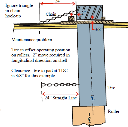
No push or pull mechanical assistance.
No wedges.
No “assist” from roller thrust reaction on tire.
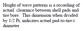
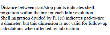
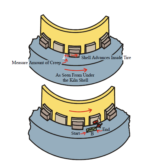
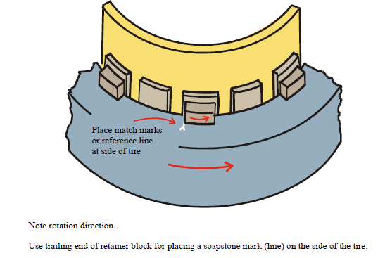
Measurement of Shell Migration to Determine Shell Pad to Tire Diameter
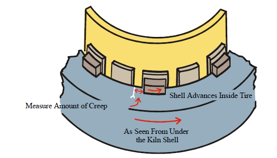
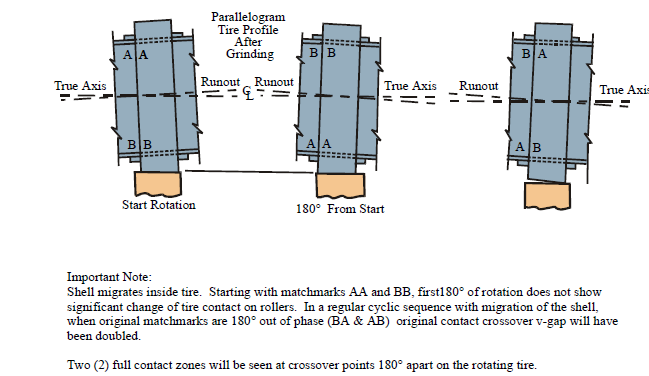
Count kiln revolutions after placing matchmarks. Measure distance between matchmarks after “X” number
of kiln revolutions, then divide that dimension by kiln revolutions during the test period to determine shell
migration (creep) for each revolution of the kiln.
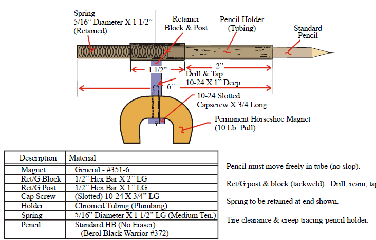
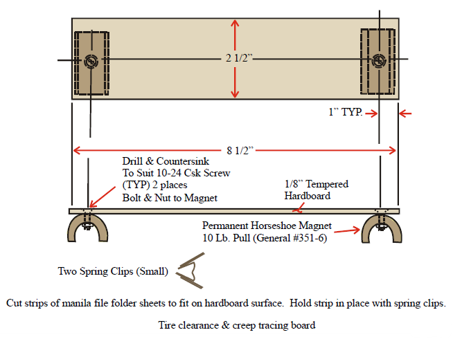
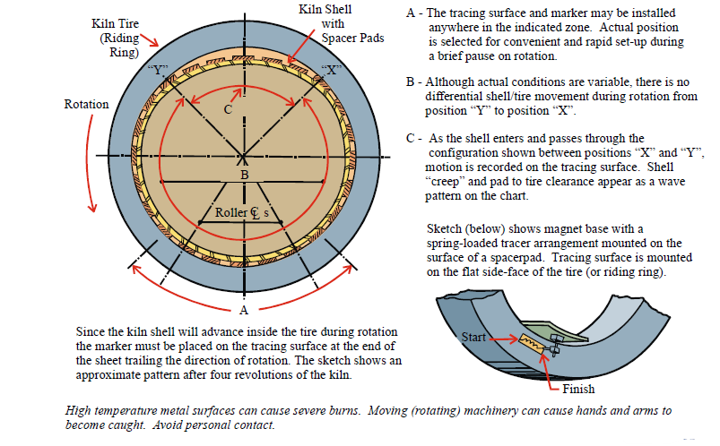
Tracing Arrangement for Recording Pad-to-Tire Clearance and Migration (Creep)
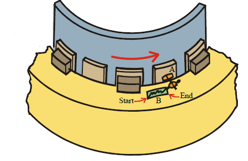
A – Magnetic base with post for spring-loaded pencil holder
B – Magnet-backed tracing surface holding panel
The kiln shell migrates within the tire;
It is not the tire that “creeps”.
In the sketch above, the tracing surface is set
on the side of the tire and the magnet-supported
pencil is placed on the trailing edge of the
card as determined by rotation direction
of the kiln.
NOTE: Kilns with floating shell pads — DO NOT PLACE MAGNETIC BASE ON A LOOSE PAD.
Maintenance
Spring-Loaded Pencil Holder for Pad/Tire Clearance and Creep Tracings
Tracing-Paper Surface for Pad/Tire Clearance and Creep Tracings
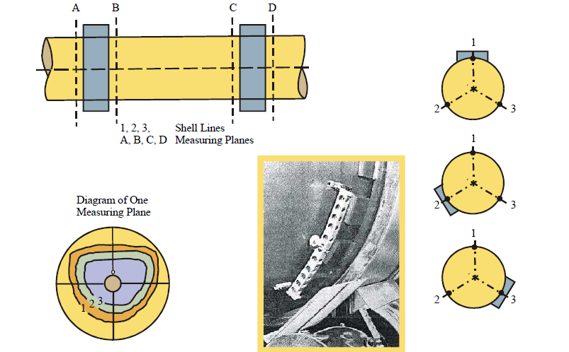
Shelltest Measuring Unit “Holderbank” System
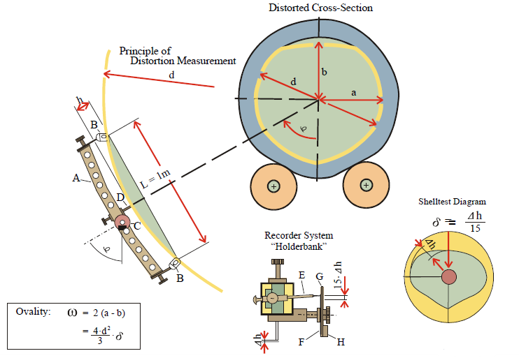
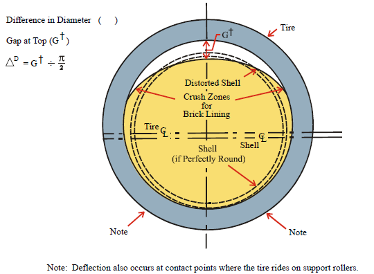
Ovality
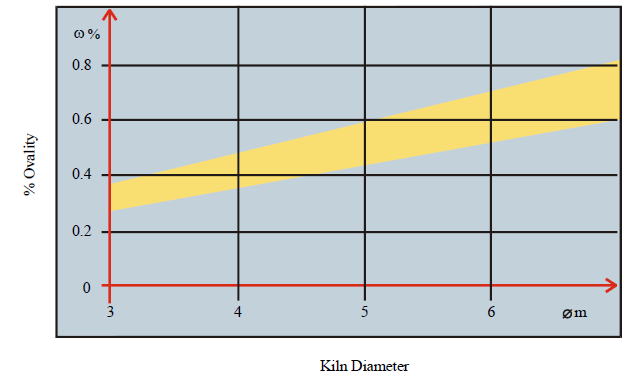
Ovality Limits as Function of Kiln Diameter
Permanent Shell Deformation
Tire Ovality – Removal of Metal May Not be Feasible
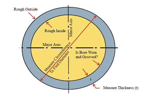
Anticipate refractory problems starting at about 0.5% shell ovality. Some older tires started (new) thin
and at critical ovality. Ovality increases when tire is cut too thin for roller supported operation.
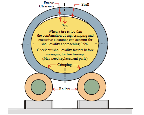
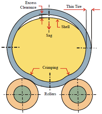
Ovality When Tire is Too Thin (and has Bad Inside and Outside Surfaces)
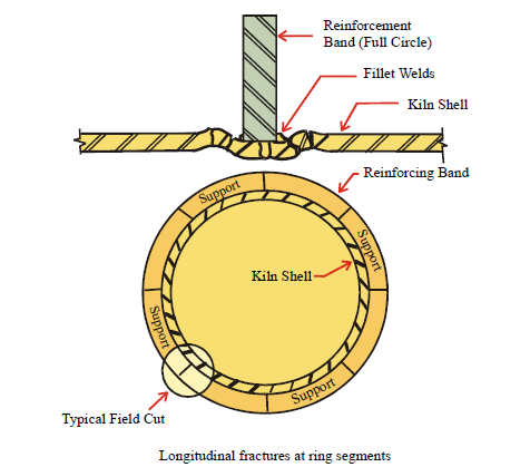
Longitudinal Fractures at Shell Pads
Thin tires and excess clearance contribute to shell ovality and fracture at pad welds or in shell plate
at toes of welds.
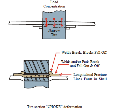
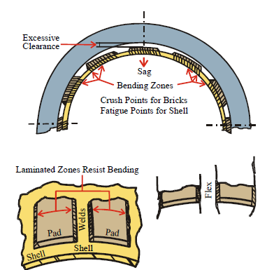
Shell ovality and pads with full length longitudinal welds, may also include pads with intermittent stitch welds.
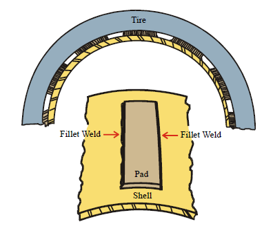
Original longitudinal welds must be removed for repair of fractures.
Hollow Tires & Rollers
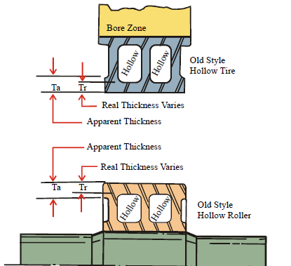
Excessive cutting & grinding on faces of cored tire and rollers has been known to put holes in surfaces
above hollows. Do not reduce original of hollow tires diameters & rollers more than 3”.
Cold Flow Ridges on Tires and Rollers
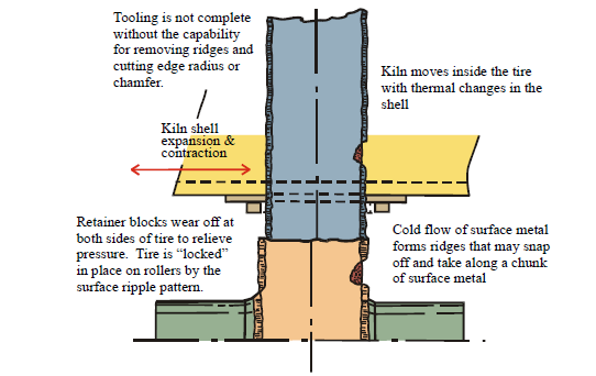
Ridges must be removed. Sided of tire and rollers must be scraped clean for test with a try square. High ridges
must be removed. Tool must be indexed for surface grinding parallel to shaft CL and true axis of tire
Warped Kiln Shell and Tire Runout
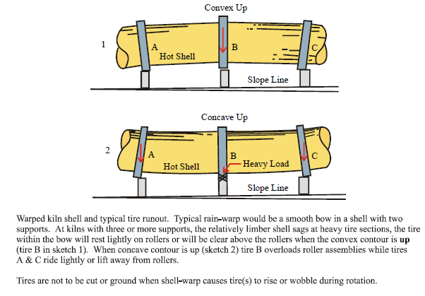
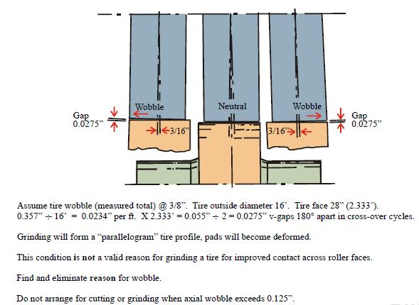
Tire Wobble When Kiln Shell is Warped
Formation of Concave/Convex Surfaces
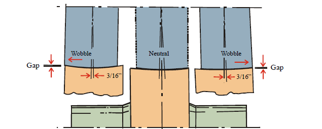
Tire wobble not eliminated. Tire face becomes convex, roller faces become concave. Surface true-up is
needed but wobble should be eliminated before any cutting/grinding work is scheduled.
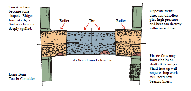
Roller faces will wear into concave contour. Tire face will wear into convex contour. With expansion/
contraction of the shell, large zone of tire moves onto a larger zone of the roller(s). Bearings are overloaded,
shell suffers from reaction to vertical misalignment.
Aftereffect of Grinding a Tire with Axial Runout
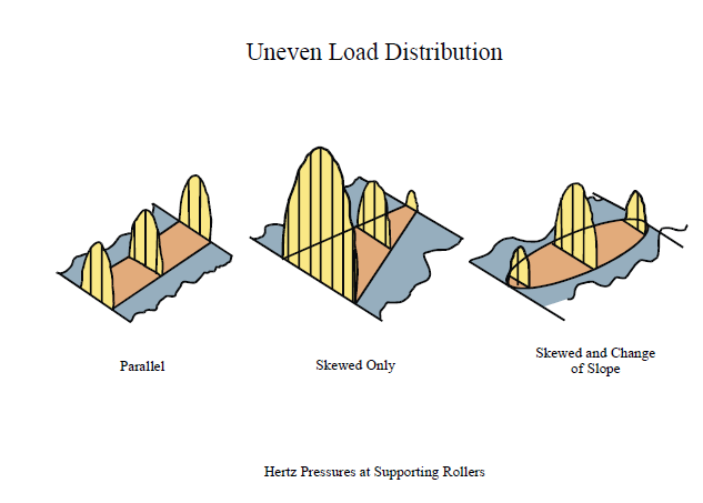
Aftereffects of Improper Roller Skewing
Tires & rollers need true-up grinding plus realignment, but ripples on shaft & bearing surfaces may
interfere with adjustments when high points meet and generate heat.
Obvious need for surface true-up, but feasibility of metal removal should be verified by ovality analysis
Grinding Prior to Kiln Shell Replacement Work
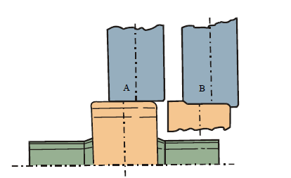
A – Assume tire not centered on rollers because of wrinkles or other shell problems. Repair work will
move the tire to normal operating position on rollers.
B – Typical wear pattern after long-term operation with tire in offset position.
Tire & rollers must be trued up before shell repair work is started, or to eliminate overload &
misalignment in case of over-expansion or changing position of the thrust tire.
Roller set points must be recalculated to suit tire & roller dimensions after finishing the grinding
process.
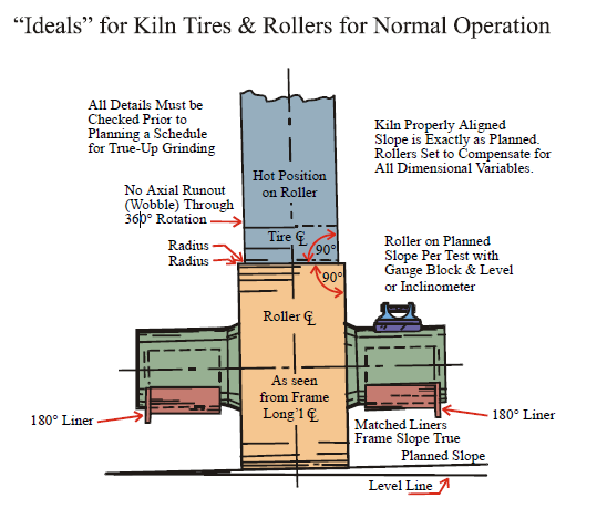
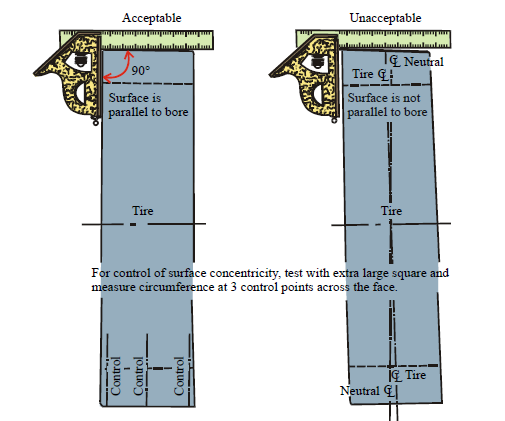
“Squareness” Control for Rollers
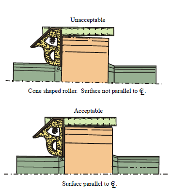
“Squareness” Control for Tires
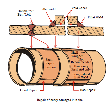
Kiln Shell Damage and Temporary Repair
Tire and Pad Lubricant for Rotary Kilns and Dryers
Kiln Shell Patch Plates Are Nothing More Than Temporary Band-Aids
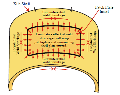
When a patch plate is installed between a riding ring and the end of the shell, anticipate warp-related
runout at the end of the shell and in the seal arrangement.
When a patch-plate is installed in shell between riding rings, anticipate riding ring wobble at the nearest
ring (or both) and also at the seal in most situations.
Start planning for shell replacement when two or more patch plates have been or must be installed.
Kiln Shell Patch Plates are Nothing More than Temporary Band-Aids
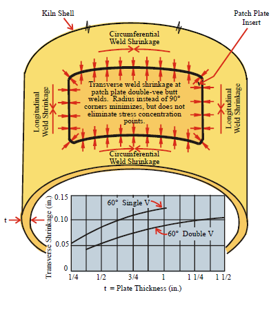
In sketch all welding is done double-Vee (butt joints)
Patch plate is restrained at all edges.Transverse weld shrinkage for plate thickness is shown in chart. Yield point of adjacent
plate surfaces would be exceeded if the shell would not be free to move in any direction in reaction to weld shrinkage stress forces.
In actual installation and welding of shell patch plates and other inserts, limited shell plate movement is possible but combined weld shrinkage stress forces warp the surfaces within and around the patch plate or “add-on” fixture. Base metal at the welds is not far from the yield point after welding.
Rotary Kiln Installation and Maintenance Repair
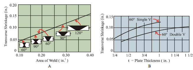
Equations For Calculating Shrinkage-
Transverse Weld Shrinkage (shrinkage perpendicular to the axis of a weld) is particularly important when the
shrinkage of individual welds is cumulative as, for example, in the shell-to-shell connections between rotary kiln
(and similar machines) riding ring positions (support points). Unless allowances are made for transverse weld
shrinkage – usually by spreading the joint open by the amount it will contract after welding – the cumulative
shrinkage of several shell-to-shell connections could be great enough to significantly shorten the span between
preset riding ring retainer locations or scribed reference lines.
For a given weld thickness, transverse shrinkage increases directly with the cross-sectional area of the weld. The
large included angles in (A) are for illustrative purposes only.
Source – Adapted from text in “The Procedure Handbook of Arc Welding” published by the Lincoln Electric
Company.
Arrangement for Removing Bearing Housing End Plate
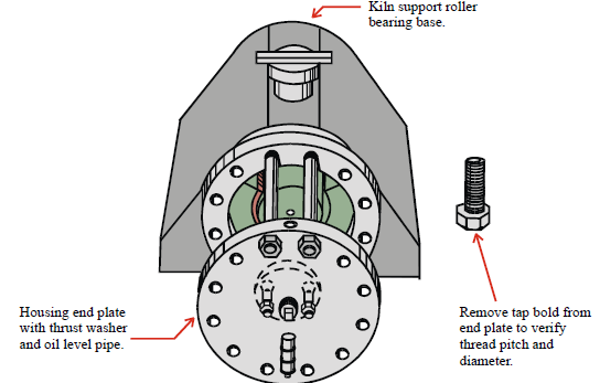
Prepare rods (cold rolled steel) for installation as shown, nuts are shown in position for safety stops, but
washers or short bars may be welded at end of rods for equally good results. Rods should not be more
than 24” long.
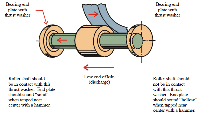
Measurement of Shell Migration to Determine Shell Pad to Tire Diameter
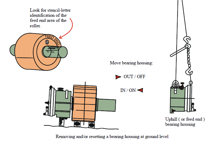
Desperation
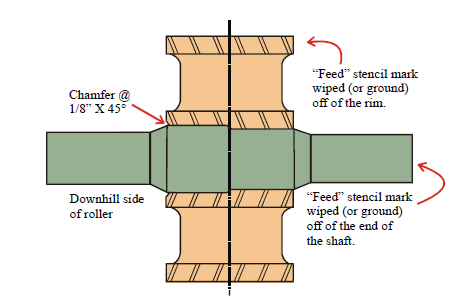
If original “feed” stencil marks have been eliminated by rubbing or by shop cleanup procedures, look for the
1/8” X 45° chamfer at one end of the roller bore zone. This chamfer will indicate the larger diameter of the
2-diameter bore for the roller.
The step-diameter lockup of roller and shaft requires the chamfer, indicating the larger shaft and bore diameter,
to be aimed toward the low, or discharge, end of the kiln.
FIGURE
“Last resort” checkout of support rollers for correct installation on support rollers.
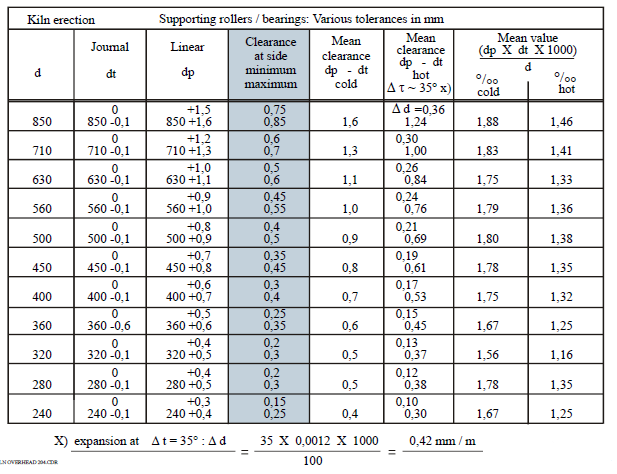
FLS Bearing Clearances in mm
FLS Conversion Kit Instructions for 1930 Type Bearing
Tracing Clearance Between Kiln Tires and Spacer Pads (Includes Shell Ovality)
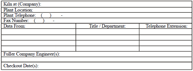
Kiln Data Sheet
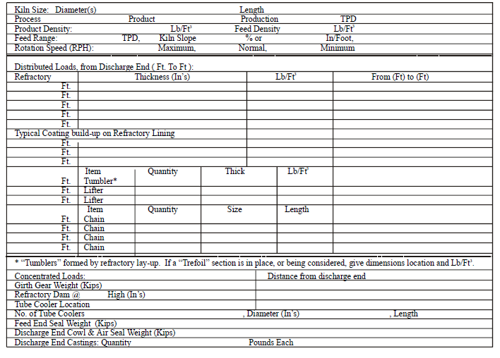
Kiln Stress Computer Program
For a Fuller Company computer data analysis of stress loading at:
– Kiln Shell
– Roller Assemblies
– Riding Ring (Tire) Ovality
Data to be obtained from plant-operator personnel, installation drawings, when available, and actual
measurements by plant and Fuller Company engineers.
CAUTION:
Drawings and records are often lost with turnover of plant personnel. Independent job shops and
contractors often supply and install replacement material and/or retrofit items which are sub-standard
or which change stress and loading factors.
With or without original reference information, actual lengths, widths circumferences and
thicknesses must be verified per accurate measurement procedures. Use an appropriately calibrated
ultrasonic thickness gauge for measurement of shell plate thickness, especially at zones affected
by erosion caused by abrasive or chemical reactions(s).
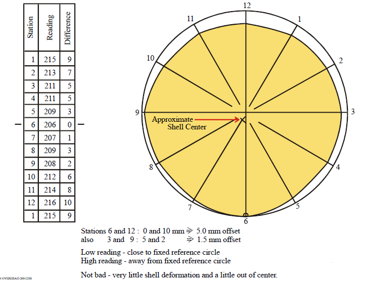
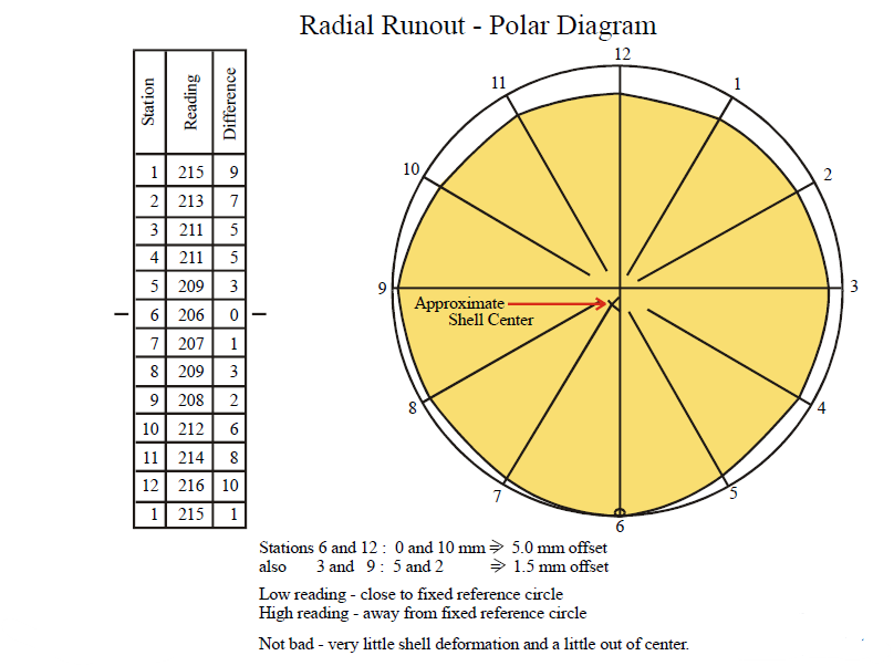
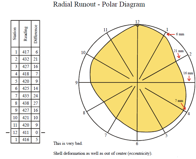
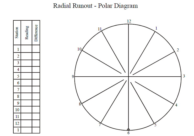
Radial Runout – Polar Diagram for Kiln Shell