Contents
Kiln System Process
[wpecpp name=”package + Updates forever” price=”250″ align=”center”]
1. INTRODUCTION
1.1 Process Description
Portland cement clinker is produced from a mixture of typically 70-90% limestone, 10-30%
clay and 0-10% corrective materials by burning in a rotary kiln. The temperature in the
burning zone is usually 1450-1550 oC and the residence time in the kiln 10-30 minutes,
depending on the kiln system.
The raw materials are blended and proportioned in accordance with the required chemical
composition. Then they are dried and ground to a fineness of 10-15% + 0.09 mm, before
being mixed with recuperated dust from cooling tower and electrostatic precipitator or baghouse
filter. Following this, they are then homogenized to a variation level in the chemical
composition corresponding to the obtainable analytical precision (Std.dev (LSF) = 0.5,
Std.dev (SIM) = 0.03, Std.dev (ALM) = 0.03) and finally fed to the kiln system.
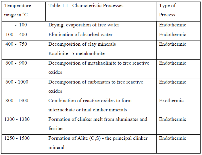
The processes taking place in the kiln system consist of a temperature dependent
decomposition of the raw material minerals according to their nature, followed by a
recombination of the liberated free reactive oxides forming clinker minerals, the most
important being C4AF, C3A, C2S and C3S.
The clinker formation sequence as a function of the temperature can briefly be characterized
as shown in following Table 1.1.
The processes take place in an oxidizing environment. Reducing conditions are normally not
present in the system or limited to smaller specific zones for reducing the NOx content in the
combustion gas.
Among the chemical processes described above, the reaction rate of the first five groups of
reactions, comprising the decomposition of the minerals in the raw meal and the liberation of
the reactive oxides, is determined by the rate of the heat transfer to the solid material. The
reaction rate of the two last groups of clinker forming reactions is determined first by the
contact rate of the mutual chemical reactive components present in different solid phases, and
later in the burning zone by the diffusion of the reactive components in the clinker melt.
The overall chemical reaction transforming the mixture of raw material minerals in the raw
meal into the mixture of clinker minerals in the clinker is endothermic i.e. heat consuming.
The order of magnitude of the theoretical amount of heat required is shown in the following
Table 1.2:
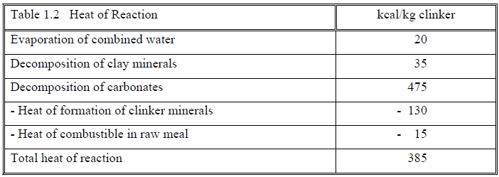
The heat of reaction is the theoretical heat required for the clinker formation and may vary as
a function of the mineralogical composition of the raw meal. Apart from the theoretical heat
of reaction, heat is lost with the excess air from the cooler, residual heat in clinker, radiation
from the hot surfaces of clinker cooler, kiln and preheater/calciner and finally with the kiln
exit gases. Part of the heat in the cooler excess air and in the kiln exit gases may be utilized
for drying of for example raw materials and coal.
The most commonly applied combustibles are coal and petcoke, but also natural gas and
heavy fuel oil are frequently applied. During recent years the principal fuels have, in some
places, been partly replaced by hazardous waste fuel, rubber tyre chips and other combustible
waste products.
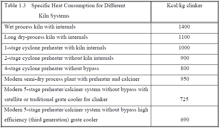
The total specific heat consumption in kcal/kg clinker supplied with the fuel depends on the
kiln system used and has decreased considerably due to the development of new, more heat
efficient kiln systems.
The following Table 1.3 illustrates this development.
In a modern kiln system where the rate of heat transfer determines the reaction rate, the
endothermic processes take place in the preheater and the calciner, while the major part of the
diffusion controlled processes, which require longer residence time at an elevated
temperature, still take place in the rotary kiln itself.
Dry-process kiln systems are always preferred to wet kiln systems, unless the humidity in the
raw materials exceeds 20-30% or the fuel price is insignificant.
Unless special considerations for building height etc. are required, the number of cyclone
stages in the preheater is normally selected according to the natural humidity in the raw
materials. This is motivated by the desire to use the hot exit gases from the preheater for
drying the raw materials in the raw grinding installation and possibly also the coal, where a
coal grinding installation is included.
The drying requirements depend on the “in-situ” moisture content of the raw materials and the
coal as well as the raw material handling and storage. The general lay-out of the quarries and
the applied exploitation and storage methods should be optimised to ensure minimum
moisture content in the raw materials.
The drying capacity of the exit gas is dictated by the temperature and the quantity of the exit
gas as well as the type of grinding installation. If the grinding circuit(s) is capable of using all
the exit gas, the relation between the drying capacity and the number of cyclone stages is
approximately as shown in Table 1.4.
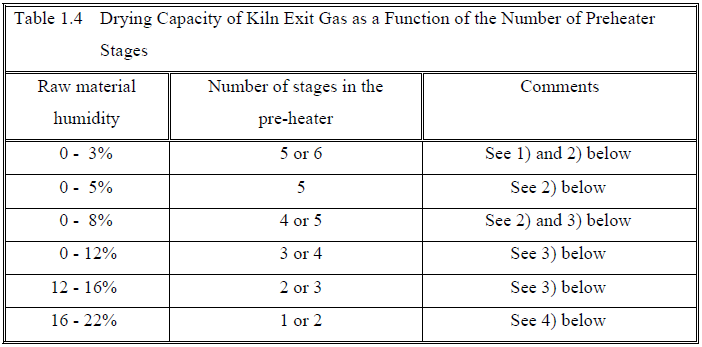
1) The choice is determined by the relation between fuel and power costs.
2) The installation costs and possible limits of investment may prevail over the longterm
optimum choice.
3) The seasonal variations become important and it might be worthwhile working
with a heat generator for the mill(s) in the wet period, if this is of limited duration,
alternatively to split the feed between the two topmost cyclone-stages in this
period.
4) A split between stage 1 and 2 is normally made to control the exit gas temperature
to the level required for drying. The grinding is normally wet and the drying is
synchronous with the kiln operation in a drier-crusher or similar.
1.2 Factors Influencing the Optimum Choice of Kiln System
Some of the important factors to take into consideration when selecting a new kiln system are
the following:
Market conditions:
-Production capacity tpd
-Product quality
-Future capacity requirements
The required product quality is determined by the different potential end-uses of the cement
in the market area and may vary in accordance with the construction activities in the market
area during the expected lifetime of the plant. In some areas low alkali cements are prescribed
due to the presence of active silica in the aggregates, which may give rise to alkali-silica
expansion, while special constructions may require special cement properties, as for example
sulphate resistance or low heat of hydration.
When deciding the required production capacity, the expected future cement demands should
also be taken into consideration, as it is often justified to prepare the plant, including the kiln
system, for a gradual uprating in accordance with an expected future increase in the cement
demand.
Raw material quality:
-Minor components
-Raw meal characteristics
-Circulation of volatile components
Type of fuel:
-Availability
-Quality
The first and invariable requirement regarding the raw materials is quite obvious. It must be
possible to make a raw meal which eventually will give a clinker quality corresponding to the
required properties of the type of cement which should be produced. However, even when
this requirement is fulfilled, the raw materials as well as the fuel may in many cases be far
from ideal from a quality point of view as well as from an operational point of view. The raw
materials may have high contents of certain hard minerals difficult to grind, which will
influence the burnability. The fuel may be a coal with a low volatile content and/or high ash
content, which requires special combustion conditions such as high temperature or long burnout
times. Further, the raw materials and fuels may have relatively high contents of volatile
matter or minor components such as chloride, sulphur or alkalis, which may influence the
operational stability and the product quality in such a manner that the installation of a by-pass
is required.
In spite of these inconveniences, dictated by nature, the supplier of machinery and
engineering services must be able to supply a plant design including equipment, which will
ensure trouble-free operation and production of cement of the required quality.
Legislation
Many countries have introduced maximum emission limits for dust NOx and SOx. The limits
currently specified in TA-Luft (1986) and the expected future limits in Germany are for
normal fuels:
Table 1.5
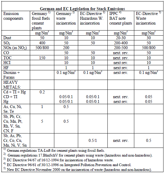
The current maximum limits of dust, NOx and SOx are expected to be further reduced in the
near future. If the plant uses waste fuels, even stricter emission limits are stated, comprising
CO, heavy metals, dioxines and furanes, organic compounds and inorganic halogen
containing gaseous compounds.
The plant should be designed for the strict fulfilment of the local regulations for maximum
permissible emissions.
Profitability:
Current and expected future cement prices
Production costs – specific heat consumption
– specific power consumption
– manpower requirements
Investment costs
Equipment reliability and availability
Local conditions
Finally, the profitability of the kiln system should be ensured, comparing the obtainable
cement prices with the expected costs of production and project financing.
The main development efforts have been concentrated on improving the profitability by
reducing the specific heat and power consumption and have resulted in following trends:
Larger production units with lower manpower requirements
-Lower heat consumption
-Lower power consumption
-New systems/components
-Improved emission control
These tendencies are illustrated in Figures 1.1 and 1.2.
In a modern F.L.SMIDTH dry-process kiln system, preheating of the raw meal up to the
calcination temperature takes place in a cyclone preheater with up to 6 stages. The major part
of the calcination process may take place in a separately fired stationary calciner. The
remaining part of the raw meal calcination as well as the final heating to the temperature
required for the clinkering process are carried out in a rotary kiln without internals.
Cooling of clinker is usually performed in a grate or planetary cooler of the well proven
F.L.SMIDTH Folax / Coolax / SF Cooler or Unax design.
The present F.L.SMIDTH programme of dry-process kiln systems includes seven main types,
each of which with its own special advantages and field of applications.
The seven F.L.SMIDTH dry-process kiln systems are called:
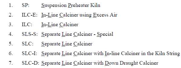
The seven F.L.Smidth dry-process kiln systems are shown in Figure 1.3.
The main features of the six systems are described in the following chapter.
The new-developed and improved technology is not only utilized for new plants, but also for
uprating and modernization of existing plants to meet increased cement demands and ensure
that the plant is still competitive in the future.
The feasibility of modernizing an existing kiln system depends on the required production
increase, the stop time required for the modifications and the expected savings in maintenance
costs and production costs, such as fuel and power consumption.
2. KILN SYSTEMS
The various kiln systems may roughly be divided into two categories, those without tertiary
air duct and those with tertiary air duct and calciner.
In the kiln systems without tertiary air duct almost all the air for combustion has to pass the
kiln. To obtain a sufficiently high temperature in the burning zone, the excess air in the kiln
must be limited to maximum 20-30%, depending on the raw meal burnability. This means that
maximum 20-25% of the fuel can be burned in the calciner. Usually this type of calciner is
operated with approximately 10-20% firing, since more fuel in the calciner will result in a
higher exit gas temperature and, in consequence, a higher specific heat consumption. The
remaining 80-90% of the fuel has to be burned in the kiln.
The kiln systems without a tertiary air duct can operate with a planetary cooler, which
simplifies the operation and reduces the specific power consumption of the kiln system
compared to kiln systems with grate cooler.
In the systems with tertiary air duct, the fuel combustion in the kiln can be reduced to 300-
320 kcal/kg clinker for the three-supports kiln and 330-360 kcal/kg clinker for the short twosupports
kiln with a normal excess air level. Since the kiln dimension partly depends on the
amount of fuel to be burned in the kiln, it is obvious that a kiln system with tertiary air duct
will have a much larger output than a kiln system without tertiary air duct for a kiln tube of
the same dimensions.
A kiln system without tertiary air duct designed for a production of 4000 tpd will have a
diameter of about 5.5 m or larger. Hence, a required capacity of more than 3500-4000 tpd will
call for a kiln system with tertiary air duct for the combustion air to the calciner. For example,
a kiln of the same dimensions included in an SLC kiln system will have a maximum
production of approximately 10,000 tpd.
The kiln systems with tertiary air ducts must, however, operate with a grate cooler instead of
a planetary cooler. This is definitely a disadvantage in terms of complexity of the installation
as well as specific power consumption. A kiln with a grate cooler has a specific power
consumption which is approximately 5 kWh/t clinker higher than the specific power
consumption of a similar kiln system with planetary cooler.’
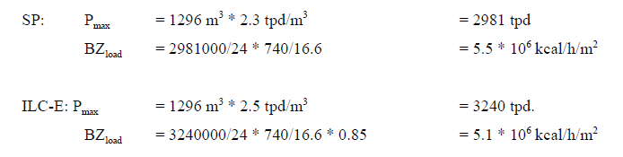
The thermal load of a kiln system is expressed in two different ways:
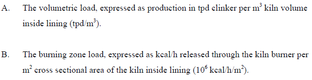
Typical ranges of the volumetric and the burning zone load for the different kiln systems are
shown in Table 2.1.
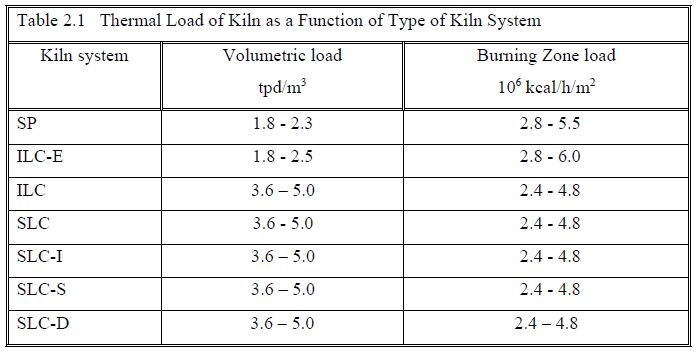
As observed from the above Table 2.1, the production capacity for a given kiln size depends
on the type of kiln system and the specific heat consumption of the fuel burned in the kiln.
Kiln Systems without Tertiary Air Duct:
Kiln Systems with Tertiary Air Duct:
2.1 SP: Suspension Preheater Kiln
The SP kiln system was introduced in 1962 and is often designed with planetary coolers and
single-string preheater towers with 1-6 stages of cyclones.
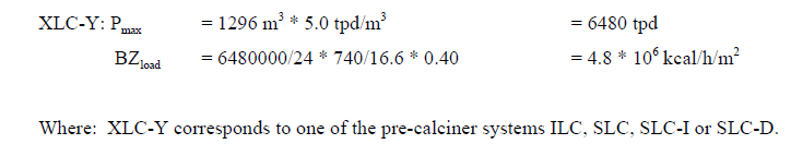
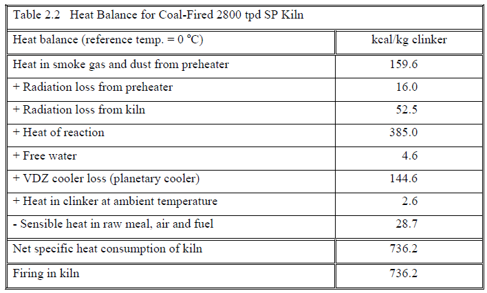
An example of a modern single-string 5-stage SP preheater kiln system is shown in Figure
2.1. The temperature and pressure profile is shown on the flow sheet in Figure 2.2 and a
typical heat balance in Table 2.2.
Features:
• Normal capacity range 600-3,000 tpd clinker.
• Ratio of firing in riser duct: 0-15%.
• Maximum possible range for by-pass of kiln gases: 0-30%.
Advantages:
• Planetary cooler can be employed.
• Lower specific power consumption (with planetary cooler).
• Simple operation – suited for manual control.
• Lowest investment costs for small capacities.
• A higher chloride content in the kiln feed can be accepted than for pre-calcining
systems with tertiary air duct (without by-pass).
For smaller to medium capacities, the simple SP system offers the lowest investment costs,
low power consumption, easy operation and reliability. The system should not be abandoned
just because it is considered not to represent the latest technology.
The cooler type can be chosen between the planetary cooler and the grate cooler. The grate
cooler is sometimes preferred if the installation is foreseen for a future expansion of the
production capacity by installing a calciner string, converting the system to an SLC system.
In an SP kiln system with 4 or more stages, the material temperature in the preheater reaches
calcination temperature and the degree of calcination of the material introduced into the kiln
may be up to 50%.
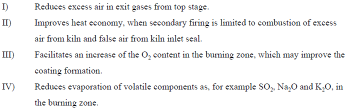
In some cases a minor firing in the riser pipe, 5-10% of the total fuel consumption, can be
advantageous for the following reasons:
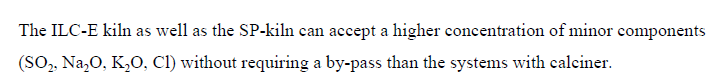
This kiln type can accept a higher concentration of sulphur, sodium, potassium and chloride
than the alternative kiln systems, without requiring a by-pass. Especially in cases where the
concentration of chloride in the raw meal is high (0.015-0.020%), the SP kiln system can be
offered without a by-pass in case of good rawmeal burnability.
2.2 ILC-E: In-Line Calciner using Excess Air
The ILC-E kiln system is a further development of the SP kiln system with riser pipe firing,
where a small pre-calciner, especially developed to obtain a higher gas and material retention
time, is built into the riser pipe.
The modern ILC-E kiln system is generally equipped with a single string 4-6 stage preheater.
In connection with semi-dry systems the preheater can be equipped with 1-3 stages of
cyclones.
The kiln type is normally designed for 15-25% firing in the riser pipe. In practice, 10-15% has
proved to be advantageous, ensuring the lowest overall heat consumption and a stable kiln
operation.
An example of a modern single-string 5-stage ILC-E kiln system is shown in Figure 2.3. The
temperature and pressure profile is shown on the flow sheet in Figure 2.4 and a typical heat
balance in Table 2.3.
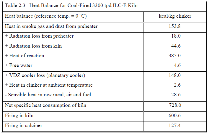
Features:
• Normal capacity range 900-3,700 tpd clinker.
• Firing ratio in calciner: 10-25%.
Advantages:
• Planetary cooler can be employed.
• Lowest investment costs for medium capacities.
• Low specific power consumption (with planetary cooler).
• Easy operation due to the high excess air level in the kiln.
• Low tendency to coating formation in the kiln inlet and the riser duct.
• Longer useful lifetime of kiln lining due to stable coating formation in the kiln.
• More chloride and sulphur in the kiln feed can be accepted than for pre-calcining
systems with tertiary air duct.
This simple system has a number of advantages, and it appears to be the optimum solution for
small and medium size plants, unless special conditions prevail, for instance NOx regulations,
requirement for a large by-pass or maximum firing with low-grade fuel.
For smaller upratings of 10-20% of the production capacity of existing SP kilns, the
conversion from SP to ILC-E kilns is frequently applied.
The cooler type can be chosen between the planetary and the grate cooler. The grate cooler is
sometimes preferred if the installation is foreseen for a future expansion of the production
capacity by installing a calciner string, converting the system to a SLC system.
In the ILC-E kiln the material in the preheater reaches the calcination temperature and the
degree of calcination of the material introduced into the kiln can reach 60%. The gas velocity
in the ILC-E calciner built into the riser pipe is reduced to approximately 10 m/s, ensuring an
extension of the retention time of gas, fuel and material compared to the SP system.
2.3 ILC: In-Line Calciner
The ILC-system was introduced in 1976 and a considerable number of systems in operation
have proved the reliability of the configuration.
The modern ILC kiln system is generally equipped with a single string 4-6 stage preheater.
The calciner vessel is built into the kiln riser pipe. The air for combustion in the calciner is
drawn from the cooler through a separate tertiary air duct between the grate cooler and the
calciner, and mixed with the gases from the kiln at the inlet of the calciner.
The most frequently applied configuration is a single-string system.
A double-string system can be designed, but due to the configuration of the system with a
built-in calciner, the tower height will increase considerably, making the ILC kiln system too
expensive and, consequently, the SLC system is normally preferred.
Existing double string SP kiln systems with high riser duct are sometimes converted to a
double-string ILC system.
An example of a modern single-string 5-stage ILC kiln system is shown in Figure 2.5. The
temperature and pressure profile is shown on the flow sheet in Figure 2.6 and a typical heat
balance in Table 2.4.
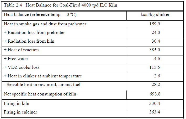
Features:
• Normal capacity range 1,500-5,000 tpd with single string preheater and up to 10,000
tpd clinker with double string preheater.
• Firing ratio to calciner: 55-60%
• Maximum possible variation in the kiln gas bypass: 0-100%
Advantages:
• High material and gas retention time in calciner due to its large volume and moderate
swirl.
• Well suited for low grade fuel.
• Low refractory costs due to the low thermal load and stable kiln coating.
• Possibility of reducing the kiln NOx in the calciner.
• Well suited for burning of coarse waste fuel (tyre chips) in the calciner.
An ILC kiln system is a true calciner system with normal gas temperatures in the calciner and
lower cyclone stage in the range of 870-900 oC. With this temperature, the decarbonisation of CaCO3 occurs rapidly. The normal degree of calcination of the material introduced into the kiln is 90-95%.
The hot air from the cooler is mixed with the kiln gases prior to being used for combustion.
This means that the combustion in the calciner is sustained by a gas mixture with 11-12% O2
only. The draught in both the kiln and the calciner is controlled by the same fan. This
necessitates a variable damper in the hot tertiary air duct in order to have some means of
distributing the combustion air between the kiln and calciner, respectively.
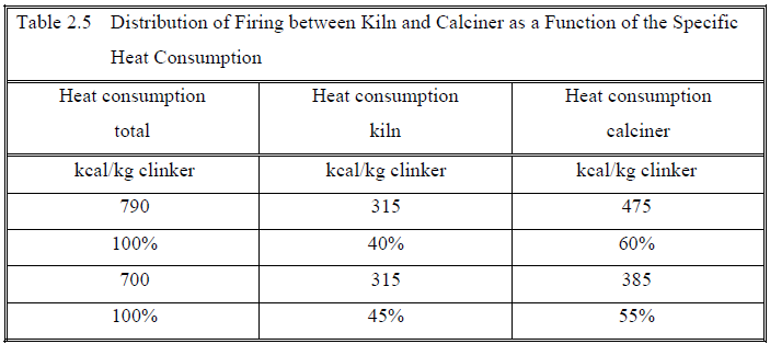
In calciner kiln systems, the normal firing in the kiln is 310-330 kcal/kg clinker, depending on
the raw meal burnability. The difference up to the specific heat consumption is introduced
into the calciner. The consequential fuel distribution between the kiln and the calciner vessel
will thus depend on the specific heat consumption of the system, as shown in Table 2.5.
Table 2.5. applies for all true calciner systems.
The ILC calciner is built into the riser pipe. The retention time of the gas in the unit should be
minimum 3.3 seconds to ensure a safe burn-out of the fuel in the vessel. The gas velocities in
the calciners are normally kept within 5-7 m/s.
The in-line calciner offers a flexibility for a by-pass between 0 and 100% of the kiln gases.
The increase in the specific heat consumption by a by-pass is 1.6-2.0 kcal/kg clinker per %
by-pass compared to 4.5-5.5 kcal/kg clinker per % bypass in an SP or ILC-E kiln system.
When considering the use of coal with a high ash content, there is a minimum value for the
inferior calorific value of the coal (Hi) to be fired to the kiln burning zone, due to the high
temperature required, whereas for the calciner there is no minimum, as the temperature is low
(900 oC) and the ash is well mixed with the raw meal and enters as a clay-component in the
clinker.
Dependent on possible requirements for NOx emission, a special NOx reducing arrangement
can be introduced into the ILC-system. The fuel for the calciner can be introduced into an
expanded portion of the riser duct. The fuel will begin to burn in a sub-stoichiometric
atmosphere, creating CO, which in turn will reduce the NOx that was generated in the kiln.
Based on the current NOx emission regulations in North America, it is expected that all new
calciners built will have the low NOx design.
2.4 SLS-S: Separate Line Calciner – Special
The first SLC-S system was put into operation in 1988 with a capacity of 5,000 tpd. Since
then, a number of systems have been sold and commissioned.
An SLC-S kiln system can be equipped with 4-6 cyclone stages in a single or double-string
preheater with the calciner placed parallel to the kiln riser duct.
In connection with semi-dry process systems, the preheater can be equipped with 1-3 stages
of cyclones.
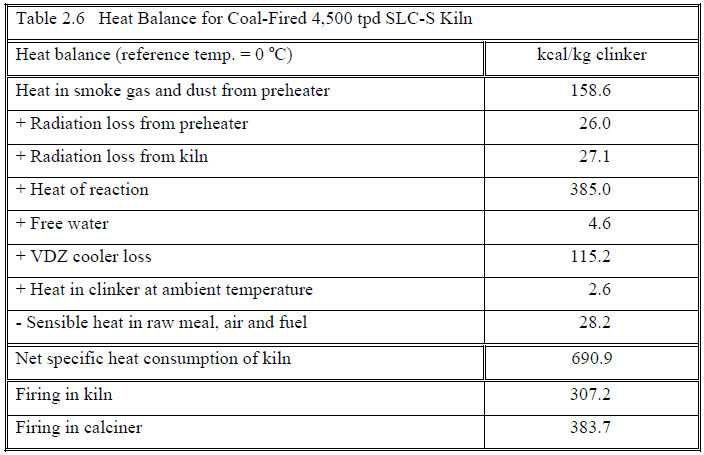
An example of a modern single-string 5-stage SLC-S kiln system is shown in Figure 2.7. The
temperature and pressure profile is shown on the flow sheet in Figure 2.8 and a typical heat
balance in Table 2.6.
This type of calciner is often used for uprating existing single and double string preheater
kilns. As the calciner is located outside the preheater, the installation of the calciner and the
tertiary air duct can be completed while the existing kiln system is still operating, and stop
time is only required for connecting the tertiary air duct to the grate cooler and the calciner
outlet to the top of the riser duct, respectively.
The SLC-S system has the following features and advantages:
Features:
• Normal capacity range 1,500-5,000 tpd clinker for one preheater string and 10,000
tpd clinker for two preheater strings.
• Firing ratio to calciner: 55-60%.
• Maximum variation in the by-pass of kiln gases: 0-30%.
Advantages:
• High material and gas retention time in calciners which dimensions are moderate,
since kiln gases do not pass through the calciner.
• Very well suited for all normal fuel types including even pulverized low-volatile coal
with or without high ash content, as the combustion takes place in hot atmospheric
air.
• The combustion temperature in the calciner can be controlled independently of the
temperature of the calcined material fed to the kiln.
• Low refractory costs due to the low thermal kiln load and stable kiln coating.
• Smallest possible tower dimensions, as the calciner can be installed separated from
the main cyclone tower.
• The two-string version of the system allows production down to 40% of the rated
capacity.
The kiln system described above has a calciner with combustion in hot atmospheric air drawn
from the grate cooler through a separate tertiary air duct which is an advantage when using,
for instance, low grade fuels or petrocoke.
Furthermore, the system offers the very advantageous feature that the temperature in the
calciner vessel and the riser pipe can be adjusted by means of the material dividing gate
below the next lower preheater stage.
With difficult-burnable coal, as for example petrocoke, anthracite etc., the temperature in the
calciner can be increased to 1000-1100 oC by sending more material to the riser pipe and less
to the calciner. Owing to this feature, optimum control of coating in the riser pipe, burn-out of
the fuel, stability of preheater etc. is obtained without changes in the preheater temperature
profile.
The gas retention time in the calciner vessel and duct should be minimum 2.7 seconds to
ensure safe burn-out of the fuel. By operating the calciner with increased temperatures the
required retention time is decreased.
The gas velocity in the calciner is usually 6.5-8.0 m/s.
The exhaust gases from the kiln and the calciner are mixed before being introduced into the
cyclone preheater. The gas temperature of the lower preheater stage is in the normal range of
870-900 oC. With this temperature level, the obtainable degree of calcination is 90-95%.
However, the SLC-S kiln system is not particularly suitable when a very high by-pass range is
required. A by-pass can be fitted to the kiln string but only a range of 0-30% by-pass of the
kiln gas is recommended.
The draught in both the kiln and the calciner is created by the same fan. This necessitates a
variable damper in the riser pipe in order to distribute the combustion air between the kiln and
the calciner.
The SLC-S system is especially suitable for secondary non-catalytic reduction (SNCR) of
NOX by ammonia injection, since the optimum reaction temperature (950-980 oC) is easily
adjusted.
2.5 SLC: Separate Line Calciner
The SLC system was introduced in 1977. Since then quite a number of systems have been put
into operation with capacities up to 10,000 tpd.
An SLC kiln system can be equipped with 4-6 cyclones stages in a double or triple-string
preheater. This kiln type is mainly used for large units above 4,500 tpd clinker, where at least
a double string preheater would be used in any case. By using separate strings for kiln and
calciner, some very important operational advantages are obtained – among others can be
mentioned the independent and accurate draught control for the kiln and calciner strings,
adjusting the speed of the individual fans without having a damper in the tertiary air duct.
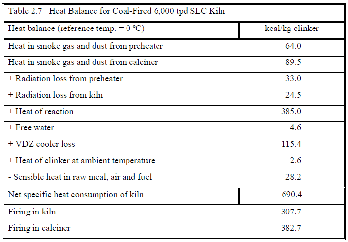
An example of a modern 5-stage SLC kiln system is shown in Figure 2.9. The temperature
and pressure profile is shown on the flow sheet in Figure 2.10 and a typical heat balance in
Table 2.7.
The double-string cyclone preheater has the precalciner placed parallel to the kiln riser duct.
Thus, the combustion in the calciner takes place in heated atmospheric air drawn from the
cooler through a separate tertiary air duct. The exhaust gas from the calciner and the kiln is
conducted through two independent strings without being mixed.
The kiln is started on the kiln string operating as a normal SP kiln system. The material from
the bottom stage is led to the kiln via a two way damper. Towards the end of this preparatory
period, the calciner string is preheated with hot air from the grate cooler, if required using
start-up burners placed in the calciner and/or the dust settling chamber in the tertiary air duct.
When the output reaches 35-40% of the nominal kiln capacity, the 2-way damper is switched
to direct the raw meal to the calciner, feed to the calciner string is started and so is the burner
in the calciner – the whole procedure taking a few minutes only. Within a few hours the full
production capacity of the kiln is obtained.
The SLC kiln system has the following features and advantages:
Features:
• Normal capacity range 3,000-7,500 tpd clinker with one kiln string and one calciner
string and up to approximately 12,000 tpd clinker with one kiln string and two
calciner strings.
• Firing ratio in calciner: 55-60%
• Maximum variation in the by-pass of kiln gases: 0-100%.
Advantages:
• High material and gas retention time in the calciner which dimensions are moderate,
since kiln gases do not pass through it.
• Very well suited for all types of pulverized coal, even low volatile coal or petrocoke,
as the combustion in the calciner takes place in hot atmospheric air, and (as an
option) the combustion temperature can be controlled independently of the
temperature of the calcined material fed to the kiln.
• Low refractory costs due to low thermal kiln load and stable kiln coating.
• Independent and accurate draught control for kiln and calciner string by adjusting the
speed of the individual fans.
• No damper in the tertiary air duct.
• Production of up to 40% of the total capacity using the kiln string only.
Like the ILC system, the SLC system is a true calciner kiln and the degree of calcination of
the material introduced into the kiln is generally 90-95%.
The fuel distribution between the kiln and the calciner is the same as mentioned for the ILC
kiln system (see also Table 2.5).
The calciner vessel is placed parallel to the kiln riser duct and is very well suited for all types
of fuels including low-volatile fuels such as petroleum coke and anthracite, because the
combustion takes place in hot atmospheric air. As an option for difficult burnable
combustibles, the calciner can be operated as a high temperature calciner. The material from
the second or maybe the third lowermost cyclone may be divided between the top and the
bottom of the calciner, whereby the combustion temperature can be controlled independently.
The gas retention time in the calciner unit should be minimum 2.7 seconds to ensure safe
burn-out of the fuel inside the calciner. The gas velocities in the calciner are usually 5.5-7.5
m/s.
The system shown in Figure 2.11 is a triple-string F.L.SMIDTH-SLC pre-calcining kiln
system with two calciners. Two systems of this type designed for a production of 10,000 tpd
are in operation in Thailand.
The system is very flexible regarding production level due to the possibility of operating 1, 2
or 3 strings, giving the continuous production range 20-100% of full capacity.
2.6 SLC-I: Separate Line Calciner with In-line Calciner in Kiln
String
In order to increase the production capacity of the double-string SLC system, a small ILC
calciner can be included in the kiln string, resulting in similar size cyclones in the kiln and
calciner string, which is an advantage, especially when high production capacities are
considered.
The first SLC-I system was commissioned in 1994 and since a number of others have been
commissioned.
The SLC-I kiln system can be equipped with 4-6 stages of cyclones with comparable sizes in
each of the two strings in the double-string preheater/calciner.
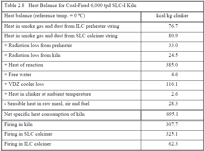
An example of a modern 5-stage SLC-I kiln system is shown in Figure 2.12. The temperature
and pressure profile is shown on the flow sheet in Figure 2.13 and a typical heat balance in
Table 2.8.
The SLC-I kiln system has the following features and advantages:
Features:
• Normal capacity range: 5,500-10,000 tpd clinker.
• Firing in SLC calciner: 40-50%.
• Firing in ILC calciner: 10-15%.
• By-pass range of kiln gases: 0-30%
Advantages:
• High material and gas retention time in the calciner, which dimensions are moderate
since kiln gas does not pass through it.
• Very well suited for all fuel types, even very low volatile fuels, as the combustion
takes place in hot atmospheric air and (as an option) the temperature in the calciner
can be controlled independently of the temperature of the calcined material to the
kiln.
• Low refractory costs due to low thermal load and stable kiln coating.
• Independent draught control for kiln and calciner string, for example by adjusting the
speeds of the individual preheater string fans.
• Production up to 50% using the kiln string only, operating as an ILC-E kiln.
• Well suited for high capacity systems, where a triple-string SLC system is not
wanted and the flexibility of the SLC system is desired.
Dependent on possible requirements for NOx emission, special arrangements can be
introduced into the SLC-I system. The tertiary air duct is split into two ducts, entering the
calciner at different positions in order to establish a zone with reducing combustion in the
bottom part of the SLC calciner. Similarly, a zone with reducing combustion can be
introduced into the ILC calciner.
2.7 SLC-D: Separate Line Calciner – Downdraft
The SLC-D is a derivation of the SLC-S calciner. The SLC-D was designed specifically for
difficult to burn fuels and for low NOx operation. Several SLC-D systems have been sold,
with the first commissioned in 1999.
The SLC-D kiln system can be equipped with 4-6 cyclone stages in a single or double-string
preheater with the calciner placed parallel to the kiln riser duct.
In connection with semi-dry process systems, the preheater can be equipped with 1-3 stages
of cyclones.
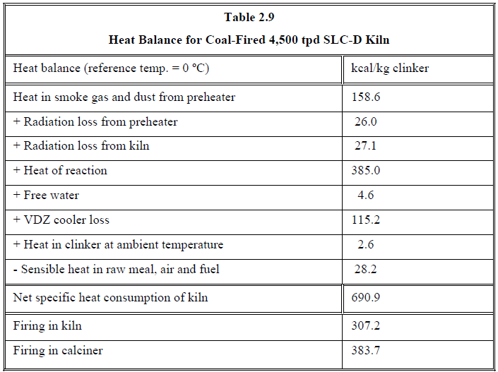
An example of a modern single-string 5-stage SLC-D kiln system (shown on Figure 2.14)
with a typical temperature and pressure profile is shown in Figure 2.15. A typical heat balance
is given in Table 2.9.
This type of calciner can be used for upgrading existing single and double string preheater
kilns as well as increasing the retention time of existing ILC calciners. As the calciner is
located outside the preheater, the installation of the calciner and the tertiary air duct can be
completed while the existing kiln system is still operating, and stop time is only required for
connecting the tertiary air duct to the grate cooler and the calciner outlet to the top of the riser
duct, respectively.
The SLC-D system has the following features and advantages:
Features:
Normal capacity range 1,500-5,000 tpd clinker for one preheater string and 4,500-10,000
tpd clinker for two preheater strings.
• Firing ratio to calciner: 55-60%.
• Maximum variation in the by-pass of kiln gases: 0-30%.
• Design to operate under reducing and/or high temperatures for NOx reduction.
Advantages:
• High material and gas retention time in calciners which dimensions are moderate, since
kiln gases do not pass through the calciner.
• Specifically designed for pulverized low-volatile coal with or without high ash content, as
the flame combustion takes place in hot atmospheric air.
• The combustion temperature in the calciner can be controlled independently of the
temperature of the calcined material fed to the kiln.
• Low refractory costs due to the low thermal kiln load and stable kiln coating.
• Smallest possible tower dimensions, as the calciner can be installed separated from the
main cyclone tower.
• The two-string version of the system allows production down to 40% of the rated
capacity.
• The ability to operate the calciner under high temperature or reducing atmosphere to
reduce NOx without impacting fuel consumption, CO emissions, or top stage temperature.
The kiln system described above has a calciner with combustion in hot atmospheric air drawn
from the grate cooler through a separate tertiary air duct which is an advantage when using,
for instance, low grade fuels or petcoke.
Furthermore, the system offers the very advantageous feature that the temperature in the
calciner vessel and the riser pipe can be adjusted by means of the material dividing gate
below the next lower preheater stage.
ith difficult-burnable coal, as for example petcoke, anthracite etc., the temperature in the
calciner can be increased to 1000-1100 oC by sending more material to the riser pipe and less
to the calciner. Owing to this feature, optimum control of coating in the riser pipe, burn-out of
the fuel, stability of preheater etc. is obtained without changes in the preheater temperature
profile.
The gas retention time in the calciner vessel and duct should be minimum 3.0 seconds to
ensure safe burn-out of the fuel. By operating the calciner with increased temperatures the
required retention time is decreased.
The gas velocity in the calciner is usually 5.0-6.0 m/s.
3. TYPE SELECTION GUIDELINES
Choosing the right kiln system configuration for a given project is a complicated task
involving a number of considerations. However, to give some idea of how to choose a new
kiln system, a number of criteria should be taken into consideration. The most important are
listed below.
3.1. Production Capacity and Investment Costs
With a given production capacity, a pre-calcining system requires considerably smaller kiln
dimensions than the simple suspension preheater kiln system.
F.L.SMIDTH normally recommend a rotary kiln diameter preferably smaller than 5 m and not
exceeding 6 m in order to ensure a reasonably long lining life.
Thus, it is advisable to employ a pre-calcining system with tertiary air duct for kiln
productions above 3,500 tpd.
On the other hand, the simplicity of the SP kiln system equipped with planetary cooler makes
it the cheapest solution for small kiln production capacities up to 2,500 tpd clinker. The semi
pre-calcining system ILC-E will in many cases be the cheapest system for productions
ranging from 2,500 to 3,500 tpd.
The new F.L.SMIDTH preheater cyclone design allows the use of a single string SP preheater
for production levels up to approximately 3,000 tpd clinker and a single string
preheater/calciner for production levels up to 5,000 tpd, still keeping the cyclone diameter
below 8.2 m. In order to ensure the lowest investment and maintenance costs it is, thus,
recommended to choose a system with a single string preheater or preheater/calciner for
production levels below 3,500 tpd and 5,000 tpd clinker, respectively, unless special
requirements such as maximum permissible tower height suggest a double string solution.
This means that the SLC system, which is always double string should normally only be
considered for new kilns with production capacities exceeding 3,500 – 5,000 tpd clinker.
The Figure 3.1 illustrates the relation between kiln diameter and production capacity for
different F.L.SMIDTH kiln systems, as well as production ranges covered by the different
kiln systems keeping the kiln diameter between 3.3 and 6.0 m.
As indicated, the ILC, SLC, SLC-I and the SLC-D systems can be supplied for production
capacities above 6,000 tpd clinker. However, in such cases the kiln diameter will exceed
5.0 m.
Figure 3.2 illustrates the relation between the kiln diameter and the production capacity for
the different dry-process kiln systems described in chapter 2.
The curves for the SP kiln system are drawn for a small and a high volumetric load of 1.8
tpd/m3 and 2.2 tpd/m3, respectively.
The curve for a small volumetric load of the ILC-E kiln system corresponds to the curve for
the small volumetric load of the SP system, while the curve for a high volumetric load of 2.5
tpd/m3 is drawn separately.
The curves for the calciner systems ILC, SLC, SLC-D and SLC-I correspond to a small and a
high volumetric load of 3.6 tpd/m3 and 5.0 tpd/m3, respectively.
The employed ranges of thermal load correspond to the design loads, while higher loads
occasionally are observed during forced production.
Figure 3.3 shows the burning zone load versus the production level for the different
F.L.SMIDTH dry-process kiln systems with a 5-stage preheater.
The burning zone load for the 5 stage-SP kiln system is calculated for a volumetric load of 2.2
tpd/m3 and a specific heat consumption of 675 kcal/kg clinker + a production dependent
radiation loss from the kiln surface, corresponding to a specific heat consumption of 730
kcal/kg clinker at 2500 tpd clinker.
For the ILC-E system, the burning zone load is based on a volumetric load of 2.5 tpd/m3 and
the same assumptions as for the SP kiln system, assuming that 15% of the fuel is fired in the
calciner.
For the calciner systems ILC, SLC, SLC-D and SLC-I the burning zone load is calculated for
a volumetric load of 4.8 tpd/m3 and a kiln firing corresponding to 285 kcal/kg clinker + a
production dependent radiation loss from the kiln surface corresponding to a total specific
heat consumption of 730 kcal/kg at 4,000 tpd clinker.
From Figure 3.3 it is seen that the burning zone load of the calciner kiln systems is
considerably lower than for the SP and ILC-E kiln systems.
The consumption of refractory brick lining in the burning zone of a calciner kiln is
consequently expected to be lower than for an SP/ILC-E kiln system.
Normal values for the refractory brick consumption in calciner kilns is in the range of 0.1-0.5
kg/ton clinker compared to 0.5-0.8 kg/ton clinker in SP/ILC-E kiln systems.
3.2 Fuels
All F.L.SMIDTH kiln types can be fired with fuel oil, natural gas and standard coal grades or
a combination of these fuels. However, if special fuels, such as anthracite, petrocoke or lowgrade
coal are to be used, this should be taken into account already when selecting the kiln
system. Generally these fuels fall into two groups, i.e. fuels with low volatile contents and
fuels with a low calorific value and possibly high content of incombustible material.
The first group is characterized by low reactivity. Due to the high temperature, the
combustion of low-volatile fuels in the rotary kiln is normally not problematic, especially
when using a modern burner, which ensures a rapid and stable ignition of all types of fuel.
However, in a precalcining system the temperature in the calciner is normally kept at
approximately 900 oC due to the simultaneous fuel combustion and raw meal calcining
process. At this temperature level, the combustion of most low-volatile fuels proceeds rather
slowly, which renders the use of low-volatile fuels in most standard precalcining systems very
problematic. In this respect the F.L.SMIDTH SLC-S calciner is an exception, as its design
allows the temperature level in the calciner to be raised without affecting the temperature
profile in the rest of the system. It is thus possible to use most low-volatile fuels in the SLC-S
calciner. On request, the SLC system can also be designed to allow high temperatures in the
calciner, although this will cause an increase in the tower height.
Low-grade fuels with very low calorific values can normally be used in the F.L.SMIDTH
calciners without difficulty. The ash formed during the combustion of the fuel is well mixed
with the raw meal in the calciner due to the high turbulence and material retention time in the
F.L.SMIDTH calciners. The amount of low-grade coal which can be burned in the calciner
may be limited by the possibilities of preparing a raw meal with a sufficiently large lime
saturation factor, which together with the absorbed coal ash complies with the required
clinker quality.
However, for rotary kiln firing there is a lower limit for the calorific value of the fuel in order
to ensure the necessary temperature in the burning zone. At the same time the mixing of the
fuel ash into the raw meal is also impeded due to the fact that the raw meal in the kiln burning
zone is already partly fused and nodulized.
Therefore a precalcining system is always preferable when using low-grade coal. In such a
system it is often possible to apply fuel with a high ash content both in the calciner and the
rotary kiln, as the total ash input to the kiln burning zone is greatly reduced because the major
part of the fuel is being introduced into the calciner.
In some plants the normal fuel types are partly replaced by combustible waste. Provided such
waste does not contain chemical compounds which influence the clinker quality or jeopardize
the smooth operation of the kiln system, all liquid and pulverized types of combustible waste
can be fired either to the calciner or through the main burner depending on the calorific value.
In the case that combustion of hazardous waste is considered, it should be observed that many
countries have special regulations with respect to temperature level and retention time as well
as stricter emission limits.
Also types of waste such as used automobile tyres, waste wood, packaging materials etc.,
which are not suitable for normal grinding, have been considered. A certain amount of such
material shredded into chips or otherwise granulated can be fired to the riser duct for later
complete combustion in the kiln inlet.
3.3 Raw Materials
The content of volatile matter in the raw materials is a principal factor in choosing the most
appropriate kiln system.
When referring to volatile matter in connection with kiln operation, it normally means
components containing potassium (K), sodium (Na), sulphur (S) and chloride (Cl), small
quantities of which are always introduced into the kiln system with the raw meal and the fuel.
On reaching the kiln burning zone, some of the volatile components will evaporate, and the
vapours are conducted with the kiln gas to the preheater, where the components again
condense.
In this way an internal circulation is formed in the kiln system and the concentration of the
volatile components in the gas from the kiln to the preheater eventually reaches such levels
that the operation is disturbed by coating formations and cyclone blockages. This is due to
increased dust stickiness caused by the increased concentration of volatile matter.
The process sets an upper limit to the acceptable content of the different components in the
raw mix and the fuel for a kiln system with a preheater and without kiln by-pass. The upper
limits tend to be slightly lower for ILC and SLC-S pre-calcining systems with tertiary air duct
and significantly lower for SLC and SLC-I precalcining systems than for SP and ILC-E kiln
systems, because the concentration of volatile components in the kiln gas becomes higher in
the pre-calcining system due to the reduced specific gas flow through the kiln in these
systems.
The normal ranges for the maximum allowable input of volatile components for the different
kiln systems are shown in Table 3.1.
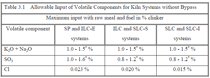
(*) The upper limits apply for a raw meal of good burnability and an ideal sulphur/alkali
ratio.
If the volatile content in the raw meal and fuel is higher than these upper limits, the kiln
system must be equipped with a by-pass through which some of the kiln gas can be extracted
from the system before reaching the preheater. In this way the internal recirculation of volatile
is reduced. By-passing a few percent of the kiln gases will be sufficient to reduce the internal
circulation of chloride in the kiln system to an acceptable level, whereas excess sulphur
circulation will require a somewhat higher degree of kiln gas by-pass.
It might also be desired to remove larger quantities of alkalis through a kiln by-pass in order
to produce low alkali cement. Sometimes CaCl2 is added to facilitate the evaporation of the
alkalis, especially the K2O.
In that case high by-pass rates are required, and the use of a pre-calcining system with tertiary
air duct is advantageous. Thus, in a pre-calcining system a higher alkali reduction is obtained
than in a conventional kiln system for a given amount of kiln gas extracted. A certain
reduction of alkali in the clinker can, thus, be obtained by the lowest possible increase in the
specific heat consumption.
The SLC and ILC kiln systems allow by-pass of up to 100% of the kiln gas, whereas the other
F.L.SMIDTH kiln systems can be equipped with a kiln by-pass for maximum 25-60% of the
kiln gas, which in most cases will be sufficient to ensure trouble-free operation even with
inferior raw materials.
3.4 Heat Economy
The heat economy of the different kiln systems depends mainly on the size, the number of
preheater stages, the rate of kiln gas by-pass (if any) and the raw mix composition and fuel
type.
For a given production level, raw mix composition, fuel type – and without kiln gas bypass –
the total specific heat consumption of the different F.L.SMIDTH kiln systems is comparable,
as illustrated by the two heat balances shown in Table 3.2.
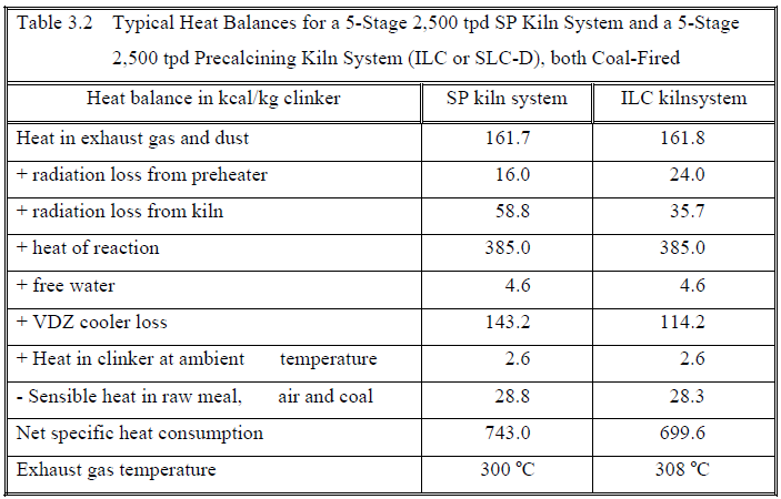
The two heat balances can be taken as typical for an SP kiln system and a precalcining system
(ILC or SLC-S), both designed with a 5-stage preheater for a production of 2,500 tpd.
It is seen that the SP kiln system has the highest radiation loss due to the greater dimensions
of the rotary kiln. The exhaust gas loss is approximately identical. The pre-calcining system
has the highest radiation loss from the pre-heater due to the increased surface area of the
calciner and the tertiary air duct. Further, the heat loss of the Unax cooler in the SP system is
higher than the heat loss of the high-efficiency Coolax cooler used for the precalcining
systems.
If the systems were equipped with a 4-stage preheater as opposed to the 5-stage preheater, the
specific heat consumption would increase by some 20 kcal/kg clinker in both cases, while a 6
stage preheater would result in a reduction of the specific heat consumption by about 10
kcal/kg clinker.
3.5 Pressure Drop and Power Consumption
Equipment demanding the most amount of power in a kiln system are the exhaust gas fan
motor(s), the cooler fan motors (if a grate cooler is used) and the kiln drive motor.
The power consumption of the exhaust gas fan(s) is mainly dependent on the total pressure
loss in the kiln system. The major part of this pressure drop occurs in the preheater. This
pressure drop can be reduced by increasing the preheater cyclone dimensions, but for a given
preheater geometry, stable preheater operation requires a certain minimum pressure drop in
order to avoid raw meal falling through the riser duct counter-current to the gas flow. The
F.L.SMIDTH LP cyclones (Low Pressure loss cyclones) which are now standard in all
F.L.SMIDTH kiln systems were developed to ensure a low pressure drop in the preheater
with reasonably small cyclone dimensions. For detailed description, see Section 4.1.
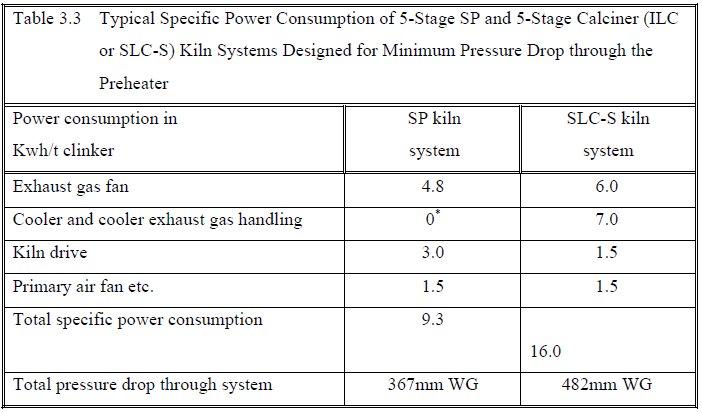
Generally speaking, the total specific power consumption of a precalcining system with grate
cooler (ILC, SLC, SLC-I and SLC-S) will be higher than that of the SP and ILC-E systems
with planetary cooler. This is due to the high power consumption of the cooling fans for the
grate cooler and a slightly higher total pressure drop in the pre-calcining systems.
In Table 3.3 the specific power consumption of an SP and a precalciner (ILC or SLC-S)
system – both with 5-stage preheater and designed for minimum pressure drop are compared.
3.6 Operation and Maintenance
For manual operation, the SP kiln system with Unax cooler is far the simplest, requiring a
minimum of instrumentation. However, the fixed degree of calcination of the material being
introduced in the kiln and the shorter material retention time within the system make the
precalcination systems well suited for automatic kiln process control. The longer lining life
and lower kiln refractory weight of the precalcining kiln systems provide longer operation
periods and less downtime for these systems and reduced refractory costs as compared to SP
kilns.
Generally, the maintenance costs are lower for a single-string kiln system than for a double or
triple-string system, and the possibility of cyclone jamming is reduced when fewer cyclones
are installed in the preheater. Consequently, a single-string preheater is always preferable to a
double-string preheater for small to medium production capacities, if there are no tower
height limitations.
4. COMPONENTS
The various components which obviously should be the latest “state of art” technology are
briefly described in the following sections.
4.1 Cyclone Preheater
As a standard feature, all the six different F.L.SMIDTH kiln systems are supplied with a 4, 5
or 6-stage cyclone preheater provided with F.L.SMIDTH LP (Low Pressure drop) cyclones.
The F.L.SMIDTH LP cyclones were introduced in 1984.
The F.L.SMIDTH LP cyclone can be considered as a reversed flow cyclone with vertical axe
with a geometry which has been optimized for different applications in pre-heaters in dryprocess
cement kiln systems.
The state of art design of the cyclones has been chosen in order to obtain the best compromise
between fulfilment of the three basic requirements for a preheater cyclone:
A) Low pressure drop.
B) High separating efficiency.
C) Small physical dimensions.
The SP and ILC-E kiln systems are normally supplied with a single-string preheater and ILC
kiln systems as single string or double string preheaters. The SLC and the SLC-I kiln systems
are supplied with a double or triple-string preheater. The SLC-S system is normally supplied
with single-string preheater for capacities up to about 4,000/tpd and double-string preheater
for higher capacities.
Figure 4.1 shows a single-string preheater with five cyclone stages and equipped with a bypass
mixing chamber.
The unique design of the F.L.SMIDTH LP cyclones ensures a high thermal preheater
efficiency and a low pressure drop in the preheater with moderate tower dimensions.
A 4-stage SP preheater can thus be designed for a pressure drop down to 300 mm WG across
the preheater itself, whereas a 5-stage SP preheater can be designed for a pressure drop down
to 350 mm WG at nominal capacity. Even with these low nominal pressure drops the
preheater operates smoothly down to 70-80% of the rated capacity without the need for
increasing the excess air percentage.
The design of three different cyclones – top stage, intermediate stage and bottom stage – is
shown in Figure 4.2.
As the LP cyclones have no inside horizontal surfaces, no material can accumulate inside the
cyclones, which in turn ensures smooth operation.
The lowest and second lowest stage cyclone are as a standard equipped with segmented
central tubes made from cast heat resistant steel. (Figure 4.3). Such a diptube has an expected
lifetime of approximately 2 years depending of the operation of the kiln.
A central tube in the bottom stage cyclone will maximise the performance of the cyclone
preheater, but problems may arise in case of elevated temperatures (above 1150oC). Regular
servicing or replacements during programmed stops are therefore to be expected.
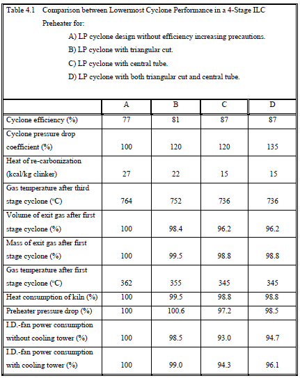
As an alternative a special design (triangular cut) of the inlet to the lowermost cyclone can
therefore be considered in the lowest stage, though still maintaining a reasonably high
separation efficiency of the cyclone. The problem of the limited lifetime of the central tube is
then eliminated.
The triangular cut inlet causes a slight increase in the pressure drop over the preheater and a
slight decrease in the separation efficiency of the lowermost cyclone compared to a similar
preheater where all cyclone stages are equipped with a central tube.
The two possible bottom stage cyclone solutions with central tube and triangular cut are
compared with a cyclone without any efficiency increasing precautions in Table 4.1.
F.L.SMIDTH preheaters (and calciners) are lined with wear resistant refractory bricks on all
cylindrical and conical surfaces. Irregularly shaped areas are lined with castable.
The wear resistant lining is fitted on a back lining of insulating blocks, which ensures a very
low heat loss from the preheater surface.
To prevent the gas from by-passing up through the material chutes between the individual
cyclone stages, the chutes are equipped with flapgates, and an excellent material distribution
in the individual riser ducts is ensured by spreader boxes with adjustable spreader plates.
Each of the cyclones is available in a number of standard diameters ranging up to 8 m.
4.2 Calciners
All F.L.SMIDTH calciners consist of a cylindrical vessel with a conical bottom. This design
allows for ample internal calciner volume, while keeping the calciner weight and surface heat
loss at a minimum.
The ILC-E calciner is shown in Figure 4.4.
In the ILC-E and ILC systems, kiln exhaust gas enters the calciner axially in the bottom cone,
and the calciner exhaust gas leaves the calciner through a side outlet at the top. Due to the
rapid increase in the cross sectional area in the conical calciner bottom a strong vortex is
created, ensuring an effective mixing of fuel, raw meal and gas.
In the ILC calciner, shown on Figure 4.5, the mixing of fuel, raw meal and gas is further
enhanced by the introduction of the tertiary air duct tangentially on the calciner bottom cone.
The resulting moderate swirl in the calciner further increases the particle retention time in the
calciner.
The SLC calciner is shown in Figure 4.6 and the SLC-S calciner is shown in Figure 4.7.
In the SLC and SLC-S systems, the hot tertiary air from the cooler enters the calciner through
the central inlet in the bottom cone and the exhaust gas leaves the calciner either through a
side outlet or – if high temperature operation is anticipated – through an outlet cone connected
to a central outlet pipe. For the same production capacity the calciners of the SLC and SLC-S
systems are smaller in dimensions than the ILC calciner, as no kiln exhaust gas is led through
the calciner. Also the calciners of the SLC and SLC-S systems are characterized by a strong
vortex formation in the bottom cone, ensuring an effective mixing of raw meal, coal and
tertiary air and a high ratio between particle and gas retention time (estimated at
approximately 4 in an industrial scale calciner).
For improving the combustion when firing with low-volatile coals such as pet coke or
anthracite in precalciner systems, a down-draft calciner can be installed in front of the regular
ILC calciner.
The SLC-D system shown in Figure 4.8 also uses hot tertiary air from the cooler. However,
the tertiary air from the cooler enters the top of the down-draft calciner where also the fuel is
added through a specially designed burner. As the air enters the calciner tangentially, it
creates as swirl of air and material around the outside walls. This high concentration of meal
protects the refractory from the high temperature that is created in the center of the calciner
with the two channel burner. The calciner exhaust gas and meal exits the bottom and enters
into the kiln riser duct area at a 135 degree angle from the kiln exit gases which ensures
complete mixing. If NOx reduction is required, staged combustion can be applied between the
down draft and the regular calciner.
All F.L.SMIDTH calciners can be fired with liquid, gaseous or solid fuels, the calciner
burners being placed so as to ensure good distribution of fuel across the calciner cross section
and rapid ignition of the fuel.
A unique feature of the SLC-S system is that the temperature level inside the calciner is
independently controlled by the position of the dividing gate effecting the distribution of raw
meal conducted to the calciner and the kiln riser duct, respectively.
Thus, by leading a relatively large amount of raw meal to the kiln riser duct, keeping the fuel
input to the calciner constant, the mean temperature in the calciner vessel can be increased to
950-1100 oC. The temperature of the exhaust gas and the degree of calcination of the raw
meal leaving the calciner will also increase.
However, on mixing with the kiln exhaust gas still containing un-calcined raw meal before
entering the calciner cyclone, the temperature of the gas/particle suspension is reduced to
approximately 900 oC. Thus, a normal temperature level is maintained in the calciner cyclone.
Similarly, a normal degree of calcination of 90-95% is maintained for the raw meal supplied
to the kiln.
The increased temperature in the calciner ensures effective combustion even of fuels with low
reactivity, for example low-volatile coals such as petroleum coke and anthracite.
A similar control of the temperature level in the calciner for the SLC system can be effected
by a dividing gate controlling the distribution of raw meal from the second lowest cyclone
stage in the calciner string between the calciner bottom and the calciner outlet pipe.
High temperature calciners comply with the same overall design as normal calciners.
The tertiary air from the cooler enters the top of the down-draft calciner where also the fuel is
added through a specially designed burner.
If NOx reduction is required, staged combustion can be applied between the down draft and
the regular calciner.
4.3 Rotary Kiln
The F.L.SMIDTH programme of rotary kilns includes 28 standard kilns with shell diameters
ranging from 3.30 m to 6.0 m.
Previously the effective length of the kilns was selected to be approximately 17 times the
diameter of the kiln inside lining, and the kiln was supplied with three supports, as shown in
Figure 4.8, as well as an extra support behind the cooler, if the kiln was equipped with
planetary cooler.
However, as the development and market conditions are constantly changing, F.L.SMIDTH
will today supply a two-support kiln with a length/diameter ratio of 12 – 13 as standard. The
two-support kiln is today supplied with state of the art components, inlet and outlet seals, self
aligning bearingssupport, tangential suspension of the live ring and kiln drive via the
supporting rollers, which all minimise the mechanical risks associated with running a short
kiln. This type of kiln, which in certain cases can be reduced to 10 in length/diameter ratio is
supplied with the ILC, SLC-S and SLC-I precalciner systems.
he inclination of the three-support rotary kiln is normally 3.5% in the SP and ILC-E kiln
systems and 4% for the kilns of the ILC, SLC-S, SLC and SLC-I systems. The corresponding
maximum speeds are 2.5 rpm and 5.0 rpm, respectively.
The two-support kilns have an inclination of 3.5% and a maximum speed of 5.0 rpm.
4.4 Clinker Coolers
The F.L.SMIDTH programme comprises three different types of clinker coolers, the Unax
planetary cooler, the Coolax grate cooler and the Duax rotary cooler.
4.4.1 Unax Planetary Cooler
The Unax cooler is a planetary cooler consisting of tubes mounted on the kiln shell. The
cooler can handle clinker of greatly varying particle size, and all the cooling air is used as
secondary air in the combustion process. Thus, no dedusting system is required. This type of
cooler is normally used with SP and ILC-E kiln systems.
4.4.2 Coolax Grate Cooler
Grate coolers for precalciner kiln systems have been used for many years.
Based on operational experience from more than 4000 grate coolers supplied by F.L.Smidth
and F.L.Smidth and considerable research and development, the design of a new basis cooler,
named COOLAX, has been completed. The new Coolax grate cooler, which replaces the
previous Folax grate cooler, is shown in Figure 4.25.
The new cooler is characterised by a very high thermal efficiency, reliability, durability, and
easy maintenance. The improved thermal efficiency is obtained by the use of the newly
developed controlled flow grate (CFG) plates, shown in Figure 4.26. The CFG plates have
transversal slots to improve the heat transfer from clinker to air and are used in the heat
recuperation zone. The CFG grate plates are cooled by the air passing through specially
designed ducts to protect them from damage due to high temperature. In the after-cooling
zone, Reduced Fall Trough (RFT) grate plates are used.
Small capacity coolers have two separate aeration sectors across the width of the grate at the
cooler inlet end, while large capacity coolers have three such sectors with separate adjustment
of the cooling air flow to prevent temperature differences arising from clinker segregation.
This feature is effective for preventing hot areas on the grates due to faster moving flows of
small red hot clinker on the surface of the clinker layer.
The robust system, controlling the distribution of cooling air to all sections of the grate area,
consisting of ducts and hollow beams, is built for long life with low wear pivot tube
connections between stationary and moving air ducts, as shown in Figure 4.27.
The Coolax grate cooler is a separate unit. Its design allows a tertiary air duct from the kiln
hood or separate off-take carrying hot cooler exhaust air directly to the calciner.
The Coolax grate cooler is therefore the standard cooler used with the ILC, SLC-S, SLC and
SLC-I kiln systems.
If very low clinker temperatures are required, a special type of roller crusher is fitted between
the grate sections. The crusher reduces the size of the clinker balls or lumps of coating to
achieve faster and more effective cooling.
The specific power consumption of the Coolax cooler is higher than that of the Unax cooler,
and the Coolax cooler requires a separate dedusting system for exhaust air which cannot be
used as combustion air in the kiln system.
On the other hand, a lower clinker exit temperature can be attained with the Coolax cooler
than with the Unax cooler.
Compared to the traditional grate coolers, the COOLAX with the controlled flow principle
offers the following advantages:
• Reduction of the specific heat consumption of the kiln system of 35 kcal/kg
clinker or more.
• About 30% reduction in the amount of cooling air and 40% reduction in the
amount of excess air to be dedusted.
• Lower overall power consumption.
• Effective and homogeneous cooling of clinker.
• Low costs of maintenance due to minimum wear on grate plates and movable
parts.
• Small external dimensions due to operation at a high specific grate load (up to 60
t/m2 per 24 hours).
The COOLAX grate cooler design is also well suited for upgrading existing grate coolers. In
addition to the energy saving and better operational performance, a retrofit also offers the
option of increased capacity within the overall dimensions of the existing cooler casing.
4.4.3 Duax Rotary Underlying Cooler
This is an alternative to the Unax and the Coolax cooler for all types of kilns up to a capacity
of 2,500 tpd. The heat recuperation ability of the DUAX cooler is excellent, its specific power
consumption is moderate and operation is simple.
On the other hand, this type of cooler requires considerable space, and the clinker exit
temperature is relatively high.
All cooling air is used as secondary or tertiary air in the kiln system, thus no separate
dedusting system is required.
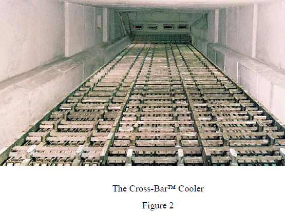
4.4.4 Cross-BarTM Cooler
Since F.L.Smidth and Fuller Company introduced the new revolutionary SF Cross-Bar™
Cooler to the cement industry in March 1997 we have been approached by many of our
customers asking
Is this proven technology?
After more than 4 years operating experience we must answer:
Yes, this is proven technology.
In the following we will review the innovative features of this cooler and present our latest
experience in both mechanical performance and process results.
DESIGN
Compared to “grate” coolers (either air-beam or conventional types), the Cross-Bar™ cooler
features four (4) new and innovative design areas.
• FIXED GRATE LINE FOR AIR DISTRIBUTION
• MODULAR DESIGN
• CONVEYING SYSTEM SEPARATE FROM COOLING SYSTEM
• INNOVATIVE COOLING TECHNIQUE…A FLOW REGULATOR FOR EACH
AIR DISTRIBUTION PLATE
Fixed grate line for air distribution
Just as for a conventional grate cooler, the grate-line sits atop the under-grate chamber.
However, because the sealed grate-line is completely stationary, the air distribution plates are
locked together in modules to form a 4 x 14 grate plate matrix. Each air distribution plate is
300 mm square, making them comparable in size to conventional grate plates.
The use of side castings and replaceable side seals are completely avoided in this cooler
because the grate-line is completely stationary. The refractory lined brickwork casing extends
all the way to the grate-line. Replacement of wear parts may be made without disturbing the
refractory.
The sealing system of the grate-line is so effective that no devices are provided for removal of
spillage from the under-grate chamber. The bottom of the under-grate chamber has a steel
floor without any openings. No spillage removal valves are provided and no spillage
conveyor is installed under any of the cross-bar coolers. This means fewer items for
maintenance. It also means lower head room requirements for new kiln line installations,
which significantly contribute, to lower civil costs.
Unlike air-beam coolers, no sealing air is required because both the grate-line and the undergrate
chamber are effectively locked. By eliminating the need for inefficient cooling air and
by eliminating the possibility for under-grate spillage, significant gains in thermal efficiency
are obtained.
Modular design
The entire cooler is constructed in modular system. Each module is four (4) grate plates wide
and fourteen (14) grate plates long (see Figure 1).
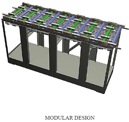
Figure 1
A single module could be a whole cooler or several modules could be assembled to form a
larger cooler. The modules are set side-by-side and end-to-end (see Figure 2).
The modules consist of an under-grate chamber with a grate-line at the top. The air
distribution plates are supported on a stationary tray system. Each module, thus, forms a 4 x
14 grate plate matrix. None of the air distribution plates move.
A stationary inlet section is installed ahead of the first module at the inlet of the cooler.
Again, the concept of “modular design” is employed. The fixed inlet is composed of five
rows of grate plates arranged in a stair-case manner. A series of air blasters are used to
prevent “snowmen” formations. The grate plates in the impact section are the same as those
used in the rest of the cooler. The grate plates or air distribution plates are significantly
different from traditional grates and, in themselves, represent one of the four new and
innovative design features of this cooler.
The “modular design” is demonstrated in that each module can be pre-assembled prior to
installation, including its refractory. As a result, existing grate coolers can be completely
replaced with a new SF Cross-Bar™ Cooler in as little as 3 to 4 weeks. Also, because all
modules are duplicates of one another, it is possible to significantly shorten delivery times.
The Cross-Bar™ Cooler makes the complete replacement of older coolers, including those
with low head room requirements, significantly easier. Several clients who have been
introduced to the Cross-Bar™ Cooler have suggested that this new cooler concept will make
retrofits to existing coolers obsolete.
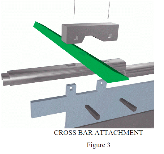
Conveying system separate from cooling system
There are two types of cross-bars: stationary and movable. The stationary and movable crossbars
alternate every row the same way as stationary and movable grate rows alternate in a
conventional cooler. A drive plate drives the movable cross-bars. The drive plate is attached
to a movable frame. Unlike the movable frame used in a conventional grate cooler, the frame
does not have to support any air distribution plates or their support beams. Quite simply,
there are no movable grate plate supports. As a result, a much lighter movable frame is
employed. This allows a simple system of linear bearings to be used.
The cross-bars are attached to the drive plate by a retainer bracket that attaches to ears
extending from the drive plate. The retainer bracket and cross-bars are locked by wedges (see
Figure 3). Replacement of the cross-bar is simply made by knocking the wedges out and
removing the retainer bracket.
Spillage is prevented from entering the plenum chamber by a drive plate cover, called a “Uprofile”
and a drive plate seal, called a “C-profile”. The “C-profile” and “U-profile” combine
to form a labyrinth type seal that prevents undergrate spillage. Since the air distribution
plates do not move, it is possible to make a very effective seal between the fixed air
distribution plates and the moving drive plate.
Each module has a hydraulic cylinder located in the under-grate chamber that imparts a
reciprocating motion to the movable frame that is parallel to the grate-line. When modules
are installed end-to-end, the movable frames of each module are connected in such a way that
they move in unison. Modules installed side-by-side do not have their movable frames
connected. In other words their speeds could be controlled individually.
The modules are installed on a five degree slope, which represents a favorable compromise
between clinker transport efficiency, and the speed of the reciprocating cross-bars.
INNOVATIVE COOLING TECHNIQUE…A FLOW REGULATOR FOR EACH AIR
DISTRIBUTION PLATE
Although there is not a fan for every grate in the cooler, the new MFR (Mechanical Flow
Regulator) ensures that every grate in the cooler continuously receives the needed quantity of
cooling air. This valve is a very simple mechanical device that has absolutely no controls.
There is no need to fine tune electronic devices, or to adjust or align mechanical linkages,
levers, or weights.
This valve is hung in the tower of an air distribution plate (see Figure 4) and pivots on a shaft.
It opens and closes according to conditions on the surface of the grate plate, to which it is
attached, providing constant cooling air. This is done automatically without the use of any
controls or human operator.
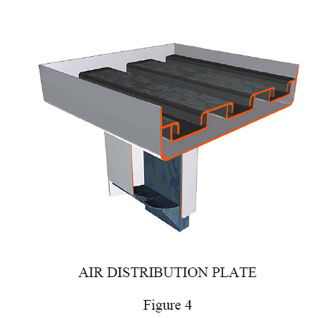
To further explain how the MFR valve works, the air distribution plate should be examined. It
is a square box of stainless steel plate fabrication that has a recessed top similar to a Spanish
tile roof. It has pockets to hold clinker, which are separated by channels that permit the flow
of cooling air along the length of the grate. The metal forming the top of the channel overlaps
the pocket slightly. This overlap shrouds the channel openings that allow the cooling air to
flow into the clinker being held in the pocket. The shroud prevents material from entering into
the channels, which are providing cooling air. Below the channels and pockets is a plenum
chamber. Each air distribution plate is installed in the cooler in a manner that prevents
leakage of cooling air or material. The only way for cooling air to go through the grate and
the bed of material above is through the tower. The pressure in the under grate chamber forces
the air up through the tower, the grate, and bed of material.
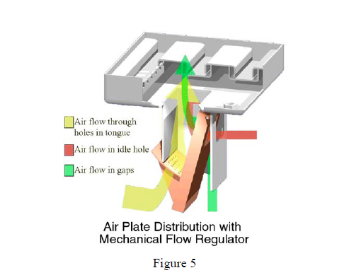
The MFR valve consists of a plate with pivot point, idle hole, and tongue (see Figure 5). The
tongue has an array of holes designed and positioned to provide a constant air flow through
the tower based on the pressure drop across the valve. As the resistance of the clinker layer
decreases, the pressure drop across the MFR increases and the valve closes. Conversely, as
the resistance of the clinker layer increases, the pressure drop decreases and the valve opens.
The pressure drop across the valve is, thus, an indication of the variations in clinker bed at the
surface of the grate plate. Because the under grate pressure is kept constant by the drive
speed controls and the air volume is kept constant by cooling fan controls, a higher pressure
drop is an indication of greater bed resistance.
It also means that without the valve a local increase in bed resistance would reduce the
amount of air flowing to that section. The MFR valve, therefore, performs the same function
as a piezometer, which causes a fan damper to open keeping fan resistance constant.
Importantly, the MFR valve accomplishes this task without electric controls. Moreover, it
does so for every grate plate in the cooler!
As noted earlier, bed resistance is attributable to a number of factors. It is imperative to
provide a constant flow of air through the grates primarily to optimize air distribution even
during upsets. Insuring constant air flow provides consistent cooling of the clinker.
Figure 6 shows the grates with the MFR valve in three different positions. On the side with
the finest clinker, the valve is hanging nearly vertical. This valve is fully open because the
pressure difference between the tower and under grate area is small (the bed resistance is
high). The valve on the far right is nearly fully closed. This is because the clinker, as
illustrated above it, is coarse and offers little resistance to air flow. Consequently the pressure
in the plenum area of the grate is low and the pressure differential between the tower and
under grate area is high. The valve has been pushed closed by this pressure differential. The
valve in the center is in an intermediary position as the clinker size is mixed and the pressure
differential is somewhere between the two extremes as illustrated by the left and right valves.
Each valve has an idle hole. This hole ensures that once the valve is fully closed the grate
will still get the designed amount of cooling air.
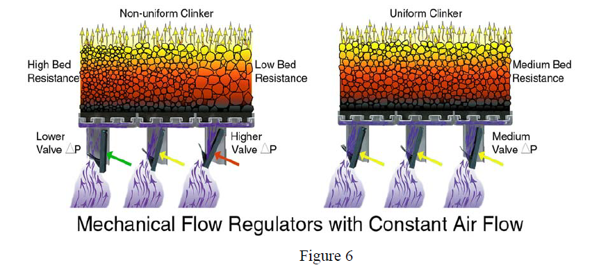
OPERATING EXPERIENCE
The latest SF Cross-Bar™ Cooler was put into operation was in United States at a 3600
MTPD cement plant with a 6-stage preheater and In Line Calciner. The cooler was replacing
a modern Controlled Flow Grate cooler in connection with a capacity upgrade
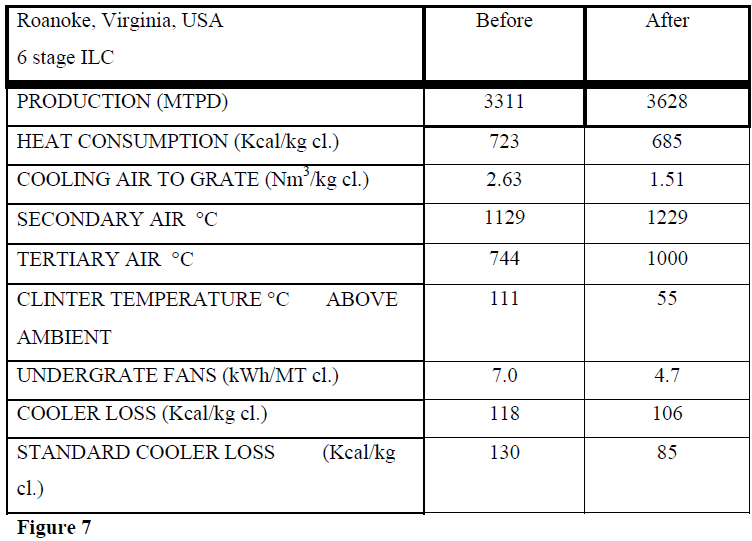
As demonstrated by the results shown in Figure 7 the cooler has from a process point of view
surpassed expectations.
Equally important, the cooler has proved very easy to handle for the operators. Even during
upset conditions it has not been necessary to adjust the cooler setting. Due to the efficiency of
the air distribution plates with mechanical flow regulators the air flow is kept constant and the
cooler will stabilize by itself.
The typical wear pattern (after 300 days of operation) is shown in Figure 8. As explained the
air distribution plates are no longer subjects to wear and only the wear parts i.e. cross bars and
sealing profiles have to be changed. The procedure for changing wear parts is very simple and
can be executed in very short time.
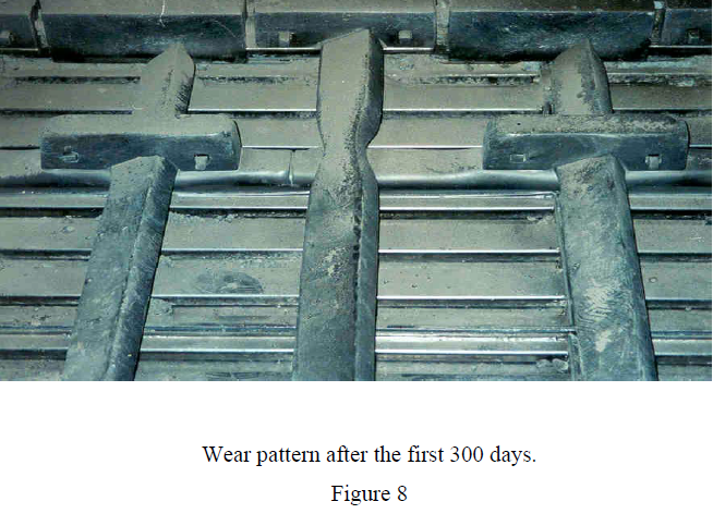
CONCLUSION
The SF Cross-Bar™ Cooler has now been in operation for more than 2½ years. Both the
mechanical and process performance has exceeded expectations. The new innovative features
of the cooler must be considered proven technology and it is our believe that this new type of
clinker cooler will set the industrial standard in the future. Clearly, the cooler technology of
tomorrow is available today.
4.5 Bypass for Kiln Gas
The F.L.SMIDTH by-pass system for kiln gases consists of a refractory lined mixing chamber
connected to the kiln riser duct, as shown in Figure 4.28.
To obtain the lowest possible dust content in the bypass gas, the mixing chamber is normally
placed on the kiln side of the riser duct just above the kiln inlet.
In the mixing chamber, the hot kiln gases are cooled to 350-400oC by mixing with cold
atmospheric air. The fresh air is tangentially introduced into the mixing chamber in such a
way that the walls in the mixing chamber are, to a large extent, protected against the sticky
dust in the by-passed kiln gas.
From the mixing chamber the kiln gas/fresh air mixture passes a dedusting installation and a
gas cleaning system, if required, before it is vented to the atmosphere. An electrostatic
precipitator possibly combined with a conditioning tower, is usually preferred as dedusting
equipment.
4.6 Accessories
4.6.1 HAF Exhaust Gas Fan
The HAF fan is a single suction, high pressure radial fan specially developed as an induceddraught
fan for cement kiln systems.
The shrouded impeller of centrifugal type with backward curved blades is designed using
FEM calculations (Finite Element Method), which ensures maximum rotor stability at
constant operating temperatures up to 400 oC.
When used as an exhaust gas fan, the HAF fan is normally equipped with a variable drive and
the efficiency of the fan itself exceeds 80%.
4.6.2 F.L.SMIDTH-SDR Kiln Control System
The F.L.SMIDTH SDR (Supervision, Dialogue and Reporting system) is a computer based
control system designed for applications in the cement industry.
The F.L.SMIDTH-SDR system provides plant operators with comprehensive operation data
which is shown on display screens and report printouts. At the keyboard the operator can start
and adjust the operating conditions of the process.
Depending on the application, the F.L.SMIDTH-SDR system is tailored to meet specific user
requirements, comprising one or more of following functional modules:
Colour Computer based operator colour stations for centralised kiln control.
Reporter Automatic, computerised reporting system.
Fuzzy For automatic fuzzy logic kiln control.
Cemscanner Automatic supervision of protective coating thickness and hot spots on kiln
surface.
4.6.3 Drier Crusher
For the different types of semi-dry process systems the drier crusher type ET is a key
machine. The drier crusher is shown in Figure 4.29.
The machine is a fully air swept hammer mill especially designed for drying and crushing of
soft materials such as chalk, marl, filter cake and slurry.
It is a very reliable machine enabling the possibility of operating on-line with the kiln system.
5. CONVERSION OF WET TO DRY-PROCESS KILN SYSTEMS
There are many possibilities of converting a wet process plant.
These possibilities may be divided into two groups depending on the basic principle applied
to the conversion:
I) Total conversion to dry process plant.
The complete conversion to a dry process plant will follow the principle ideas
already discussed in the previous sections.
II) Partial conversion to semi-dry process maintaining partly the raw material
preparation and storage.
The conversion to semi dry process is normally selected as the best solution when
the raw materials have a natural high moisture content, the existing slurry
preparation facilities have sufficient production capacity and/or filtration units are
already available.
For a dry-process clinker factory the costs of the various departments look as follows:
Turnkey Relative Prices
Raw material storage……………………………………. 33%
Raw mill department ……………………………………. 17%
Raw mill silo + kiln feed………………………………. 10%
Kiln and cooler ……………………………………………. 40%
By looking at the relative prices it is quite obvious that a solution with partial conversion of a
wet plant might turn out to be the most cost-effective solution, especially when the raw
materials have a high natural humidity, which complicates the comminution in a traditional
dry raw grinding plant.
Throughout the past 10 years a lot of different solutions have been implemented and in some
cases, the partial conversion from wet to semi-dry kiln process has turned out to be the most
economically feasible solution.
Although there are extremely many semi-dry process solutions, these can be classified in 4
different main groups of system which can be described as shown in Table 5.1.
Table 5.1. Principal Groups of Solutions for Converting from Wet to Semi-Dry Process
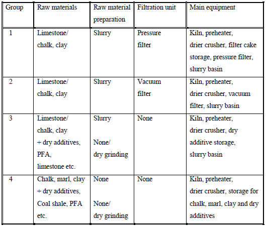
Group 1 and 2 represent the classical conversion technology based on traditional wet grinding
and the posterior usage of slurry filters to reduce the moisture content. For difficult-filterable
materials the pressure filter presses can often reduce the moisture content in the filter cake to
an acceptable level of 18-20% H2O. They are operated in a semi-automatic cycle with semiautomatic
emptying of the filter cakes. The cakes are stored in intermediate filter cake silos
and from here, fed to the dryer crusher.
The pressure filter department is expensive in installation and operation.
An example of a group 1 system is shown in Figure 5.1.
For easy-filterable materials, a vacuum drum filter can often reduce the moisture content
down to an acceptable level of 18-20% H2O. They are operated continuously with drum filter
cake directly to the drier crusher/preheater. The vacuum filter costs 15-25% of a filter press
and the filter cake silo installation.
An example of a group 2 system is shown in Figure 5.2.
For a moisture content of the feed to the drier crusher of 25.2% and an ambient temperature
equal to the feed temperature of 15 oC, the typical range of specific heat consumption for the
installation, shown in Figure 6.2, is 950-1000 kcal/kg clinker.
The group 3 semi-dry process system has been developed with the aim of avoiding the slurry
filter installation. In this system the raw materials for the process consist of a slurry and some
dry additives. Both slurry and dry additives are injected directly into the drier crusher. The
final raw meal composition is made in the drier crusher/preheater.
An example of a group 3 system is shown in Figure 5.3.
The group 4 semi-dry process system was developed as a logical consequence of the
experience with a group 3 plant (Rørdal) and the drier crusher for chalk drying.
The philosophy is to feed both the soft material (chalk, marl) with its natural moisture
content and the dry additives directly into the drier crusher and hereby obtain the raw mix
composition in the drier crusher/preheater.
By this procedure a compact system is obtained avoiding the installation of slurry filters.
An example of a group 4 system is enclosed as Figure 5.4.
The conversion of wet process plants is treated in more detail in a separate paper.
6. MODERNISATION OF DRY-PROCESS KILN SYSTEMS
The F.L.SMIDTH equipment described in the previous chapters 2 to 5 represents the state of
art in clinker pyroprocessing technology.
The system configurations and components described do not only apply to new kiln
installations, but the described concepts and components may also be applied to
modernisation of existing production lines.
The purpose of modernising an existing plant is generally to uprate the production capacity
and simultaneously increase the energy efficiency and, in consequence, reduce the production
costs as well as the maintenance costs.
Uprating of the production capacity often involves modification of the kiln system to a system
with higher volumetric kiln load as for example converting an SP kiln system to an ILC-E
system or an SLC system.
For larger production increases such modernisation may require modification or replacement
of the clinker cooler, for example when the system is converted from a system without tertiary
air duct to a system with tertiary air duct, which requires a grate cooler.
Increased heat efficiency can be obtained by various means, as for example by replacing the
normal refractory brick-lining with a highly insulating refractory lining, thus decreasing the
radiation loss from the surface, by adding more cyclone stages to the preheater, by increasing
the separation efficiency of existing cyclones, by increasing the thermal efficiency of the
clinker cooler, and by reducing the entrance of false and primary air to the kiln system.
Replacing the existing cyclones, especially the top and lower- most cyclone stages, with LP
(low pressure drop) cyclones results in a lower pressure drop over the preheater and,
consequently, lower power consumption of the kiln ID fan.
Some old ID fans have straight, radial impeller blades with efficiencies of about 65-70% only.
By replacing the impeller with a modern, high efficient impeller with backwards curved
blades the efficiency can be increased to 80-85%.
For long dry process kilns and 1 or 2-stage SP kilns with demanding maintenance kiln
internals, a considerable reduction in maintenance costs can be obtained by converting the
system to 2 or more stages SP kilns without internals.
It is, thus, in many cases advantageous to modernize existing kiln systems using the
components and equipment described in Section 4.
Most kiln conversion projects have resulted in a greatly increased production capacity as well
as considerable savings in specific heat and power consumptions and maintenance costs.
F.L.SMIDTH have successfully carried out numerous kiln conversion projects including
conversion of wet process and long dry process as well as one and two stage SP kilns to
modern dry-process kiln systems incorporating 4 or 5-stage preheaters.
Most of these conversions have involved shortening the existing kiln and connecting it to a
completely new preheater tower. As the production capacity is usually boosted by the
conversion, it has often been necessary to uprate or modify the existing clinker cooler as well.
In order to keep kiln downtime at a minimum, the new preheater tower is usually erected
above the existing un-shortened kiln while still in operation.
Four and 5-stage SP kiln systems can also be uprated. One method is to increase the capacity
of the existing preheater by replacing one or more cyclones with the space saving
F.L.SMIDTH-LP type, possibly at the same time installing an ILC-E, ILC or SLC-S calciner.
Another possibility is to install a completely new calciner-preheater string parallel with the
existing preheater tower, thus converting the kiln system to an SLC type. This conversion is
illustrated in Figure 6.1.
The latter conversion method has the advantage of a very short downtime, as the new
preheater tower can be completely erected without this affecting the production in the existing
kiln. The actual connection of the new calciner string to the existing system is extremely
simple.
The feasibility of such conversions may be critical, and it is recommended to carefully
evaluate the existing possibilities.
The F.L.SMIDTH kiln specialists have the necessary expertise and experience to assist in
evaluating the possibilities of any kiln conversion project.
Modernisation of dry process kiln systems is treated in more detail in a separate paper.
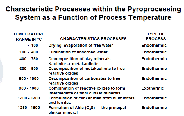
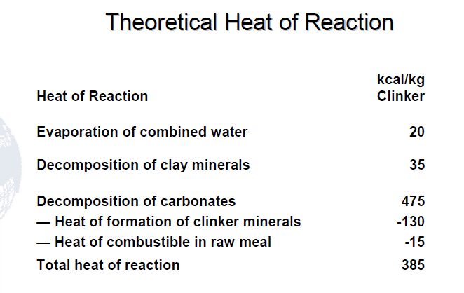
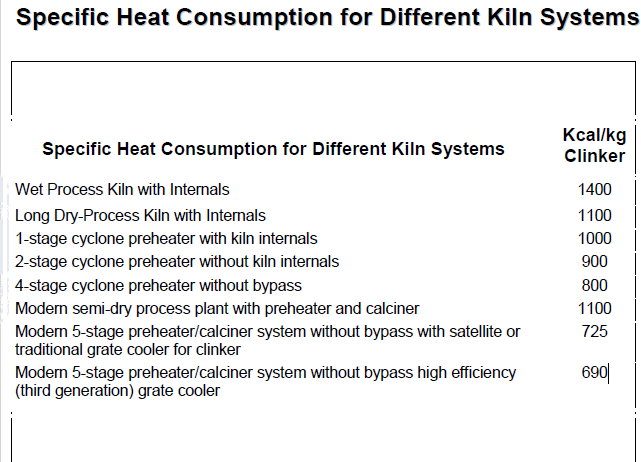
Drying Capacity of Kiln Exit as a Function of the Number of Preheater Stages
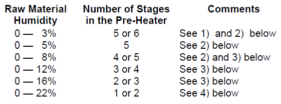
1) The choice is determined by the relation between fuel and power costs.
2) The installation costs and possible limits of investment may prevail over
long-term optimum choice
3) Depends on seasonal variations.
4) Split of feed normally made between stages 1 and 2 to control the preheater
exit temperature.
Factors to Consider When Choosing Kiln System Size and Type
Market Conditions
• Production Capacity TPD
• Product Quality
• Future capacity requirements
• Emission/environmental requirements
Raw Materials
• Quarry lifetime and homogeneity
• Minor components
• Bad actors in raw mix, e.g.. volatiles, pyrite, carbon, etc.
Fuel
• Availability
• Quality
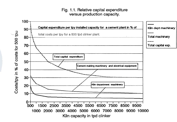
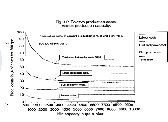
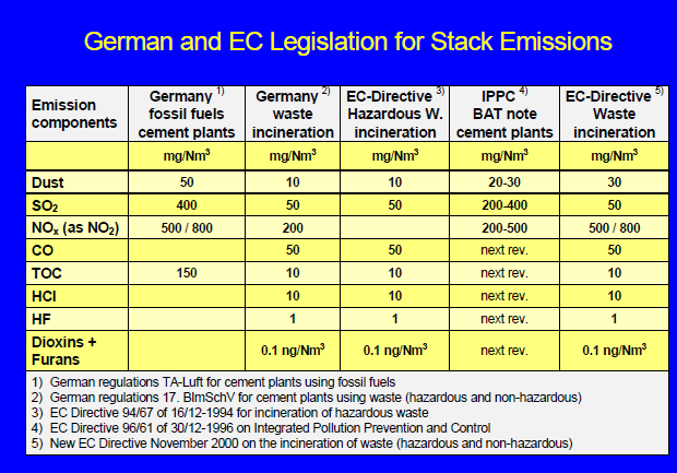
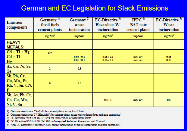
Six standard dry-process kiln system configurations
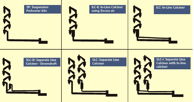
Volumetric and Thermal Load of Kiln as Function of Type of Kiln System
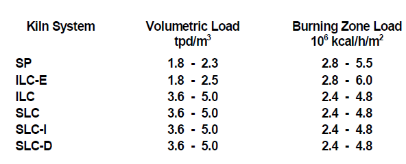
BURNING ZONE LOAD VS. KILN SYSTEM CAPACITY IN TPD CLINKER
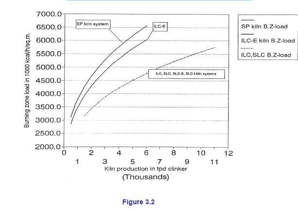
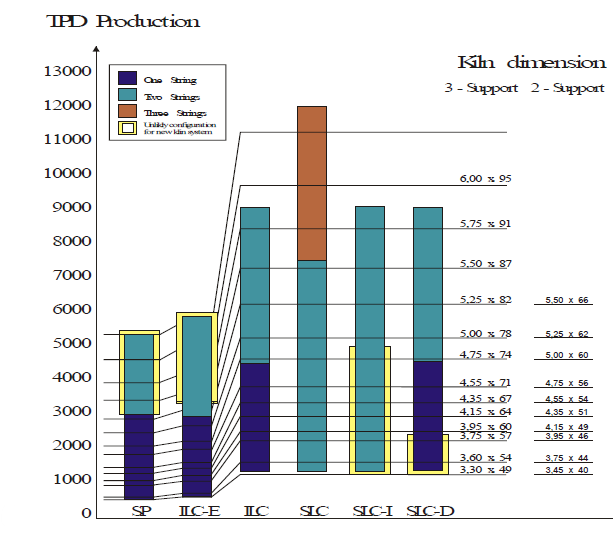
SP – Suspension preheater kiln
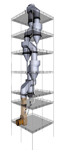
SP – Suspension preheater kiln
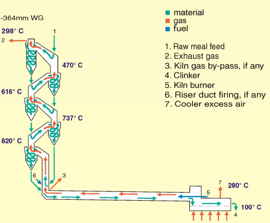
Heat Balance for Coal-Fired 3300 TPD SP Kiln
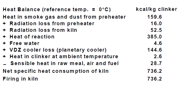
SP – Suspension preheater kiln
Special advantages
• For small capacities – the economical solution.
• Very low specific power consumption.
• Simple operation – well suited for manual control.
• Accepts higher input of chlorides than precalcining systems
with tertiary air duct (without bypass).
Features
• Normal capacity range: 700-2800 tpd.
• Ratio of firing in riser duct: 0-15%.
• Bypass of kiln gas: 0-30%.
• Planetary cooler can be employed.
ILC-E – In-Line Calciner using Excess air
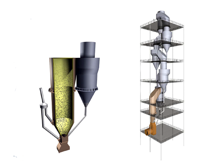
ILC-E Calciner
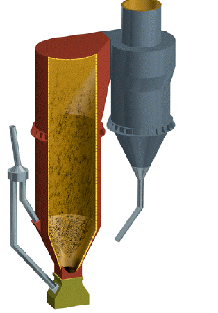
ILC-E – In-Line Calciner using Excess air
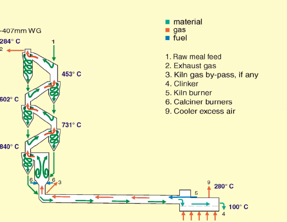
Heat Balance for Coal-Fired 3300 TPD ILC-E Kiln
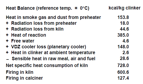
ILC-E – In-Line Calciner using Excess air
Special advantages
• Most economical solution for small and medium capacities.
• Low specific power consumption.
• Easy operation due to high excess air percentage in kiln.
• Low coating tendency in kiln inlet and riser duct.
• Long kiln lining life due to stable kiln coating.
• Less sensitive to chlorides and sulphur than precalcining systems with
tertiary air duct (without bypass).
• Smaller kiln dimensions than SP system.
Features
• Normal capacity range: 800-3500 tpd.
• Ratio of firing in calciner: 10-25%.
• Bypass of kiln gas: 0-25%.
• Calcination at kiln inlet: 50-70% (compared to 30-40% for SP operation).
• Planetary cooler can be employed.
Distribution of Firing between Kiln and Calciner
as a Function of the Specific Heat Consumption
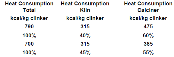
ILC Calciner
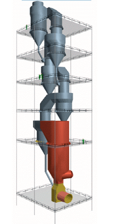
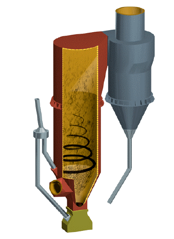
ILC-I Calciner
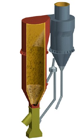
ILC – In-Line Calciner
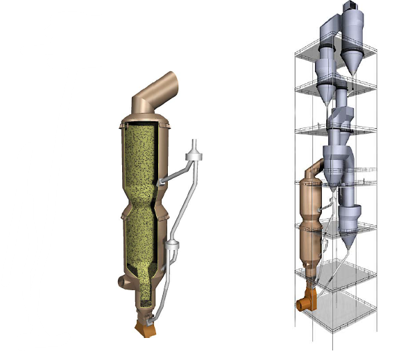
ILC low NOx
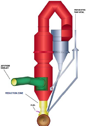
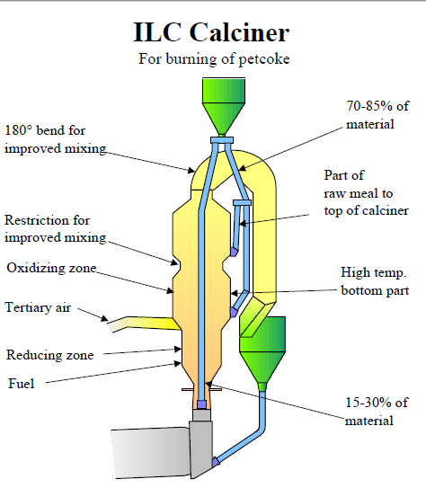
ILC – In-Line Calciner
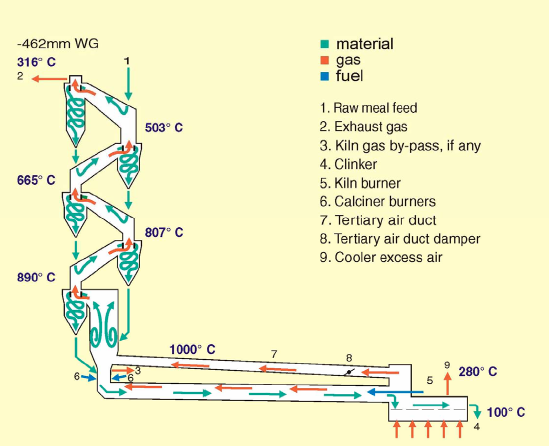
Heat Balance for Coal-Fired 4000 TPD ILC Kiln
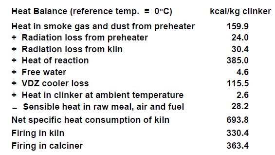
ILC – In-Line Calciner
Special advantages
• High material and gas retention time in calciner due to its large volume and
moderate swirl.
• Regulation range of up to 60% bypass of kiln gas using ILC-I version.
• Well-suited for low-grade fuels.
• Long refractory life due to low thermal kiln load and stable kiln coating.
• Lowest NOx emission among traditional calciner kiln systems.
Features
• Normal capacity range: 1500-5000 tpd, with multiple strings > 10,000 tpd.
• Ratio of firing in calciner: 55-65%.
• Normal bypass of kiln gas: 0-30%.
• Maximum bypass of kiln gas: 0-100% using ILC-I version.
• Built-in low-NOx capabilities.
• Calcination at kiln inlet: 90-95%.
SLC-S Calciner
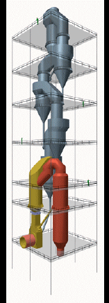
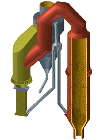
Heat Balance for Coal-Fired 4500 TPD SLC-S Kiln
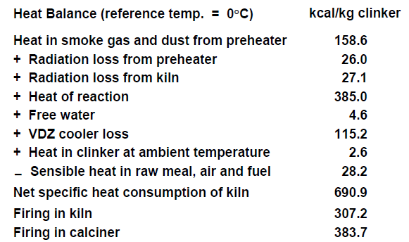
SLC – S Calciner
• Features
– Normal capacity range 1500 – 5000 tpd clinker for one preheater string and 10,000 tpd
clinker for two preheater strings
– Firing ratio to calciner: 55% – 60%
– Maximum variation in the by-pass of kiln gases: 0% – 30%
• Advantages
– High material and gas retention time in calciners which dimensions are moderate,
since kiln gases do not pass through the calciner
– Very well suited for all normal fuel types including even pulverized low-volatile coal with
or without high ash content, as the combustion takes place in hot atmospheric air
– The combustion temperature in the calciner can be controlled independently of the
temperature o f the calcined material fed to the kiln
– Low refractory costs due to the low thermal kiln load and stable kiln coating
– Smallest possible tower dimensions, as the calciner can be installed separated from
the main cyclone tower
– The two-string version of the system allows production down to 40% of the rated
capacity
SLC-D – Separate Line Calciner – Downdraft
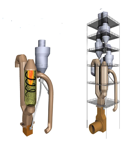
SLC-D – Downdraft Calciner
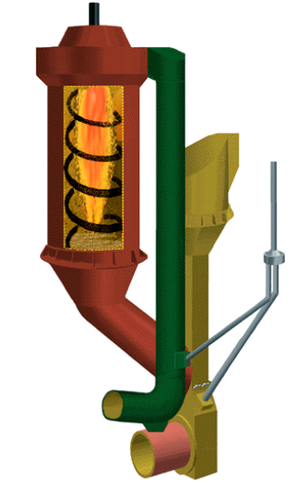
SLC-D system
Calciner with Separate Combustion Chamber
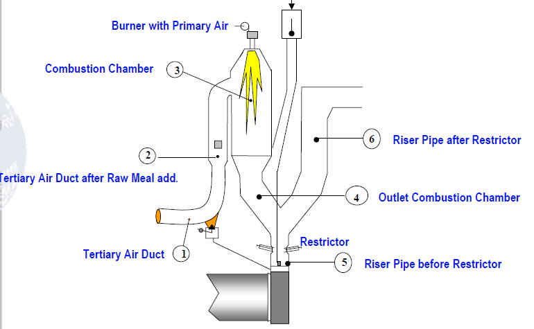
SLC-D – Separate Line Calciner – Downdraft
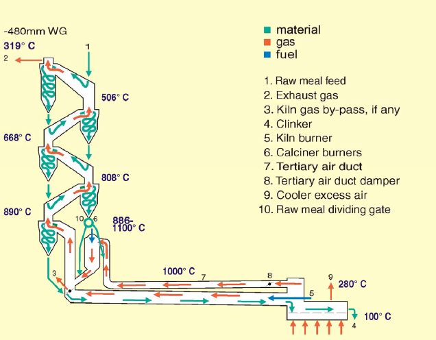
Heat Balance for Coal-Fired 4500 TPD SLC-S/D Kiln
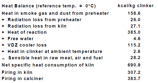
SLC-D – Separate Line Calciner – Downdraft
Special advantages
• High material and gas retention times in the calciner/ combustion chamber whose
dimensions are minimal since the kiln gases do not pass through it.
• Very well-suited for all fuel types, especially low-volatile fuels, as the
combustion in the calciner takes place in hot atmospheric air and the combustion
temperature in the calciner can be controlled independently of the temperature of
the calcined material fed to the kiln.
• Low NOx operation is possible.
• Smallest possible tower dimensions, as the calciner can be installed separately
from the cyclone tower.
• Especially well-suited for retrofits of existing SP or ILC preheaters due to very
short down time.
Features
• Normal capacity range: 1500-5000 tpd, with multiple strings > 10,000 tpd.
• Firing in calciner: 55-60%.
• Bypass of kiln gas: 0-60%.
• Maximum bypass regulation range: 30%.
• Calcination at kiln inlet: 90-95%.
SLC Calciner
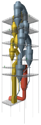
SLC – Separate Line Calciner
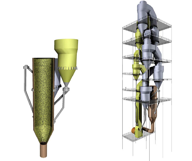
SLC Calciner
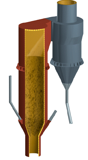
SLC – Separate Line Calciner
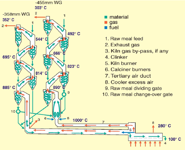
Heat Balance for Coal-Fired 6000 TPD SLC Kiln
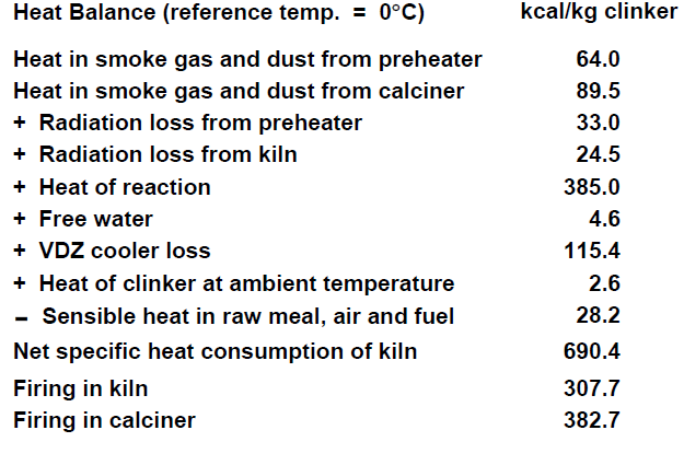
SLC – Separate Line Calciner
Special advantages
• High material and gas retention times in the calciner whose dimensions are minimal
since the kiln gases do not pass through it.
• Very well-suited for all fuel types, even low-volatile fuels, as the combustion in the
calciner takes place in hot atmospheric air, and (as an option) the combustion
temperature in the calciner can be controlled independently of the temperature of the
calcined material fed to the kiln.
• Long refractory life due to low thermal kiln load and stable kiln coating.
• Independent and accurate draft control for kiln and calciner strings by adjusting
speed of individual fans.
• No damper in tertiary air duct.
• Production down to 40% of capacity using kiln string only.
• Production down to 20% of capacity for three-string version.
Features
• Normal capacity range: 3000-7500 tpd (one C-string), 7500-12,000 tpd (two Cstrings)
• Firing in calciner: 55-60%.
• Bypass of kiln gas: 0-100%
• Maximum bypass regulation range: 30%.
• Calcination at kiln inlet: 90-95%.
SLC-I – Separate Line Calciner with In-line Calciner
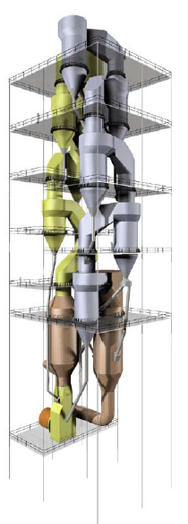
SLC-I – Separate Line Calciner with In-line Calciner
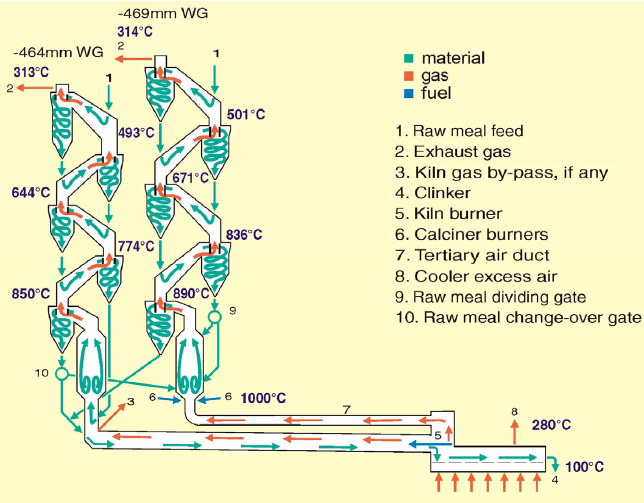
Heat Balance for Coal-Fired 6000 TPD SLC-I Kiln
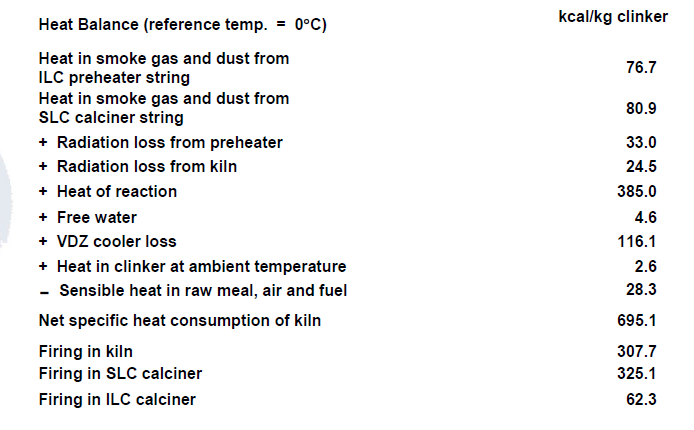
SLC-I – Separate Line Calciner with In-line Calciner
Special advantages
• Very well-suited for all fuel types, even low-volatile fuels, as the
combustion in the SLC calciner takes place in hot atmospheric air, and (as an
option) the combustion temperature in the SLC calciner can be controlled
independently of the temperature of the calcined material fed to the kiln.
• Independent and accurate draft control for kiln and calciner strings by
adjusting speed of individual fans.
• Production up to 50% of capacity using kiln string only (ILC or ILC-E)
• Same cyclone sizes and feed systems for both strings.
Features
• Normal capacity range: 6500-10000 tpd.
• Firing in kiln string ILC: 10-15%.
• Firing in calciner string SLC: 40-50%.
• Bypass of kiln gas: 0-30%.
• Calcination at kiln inlet: 90-95%
ICPS – Kiln Systems
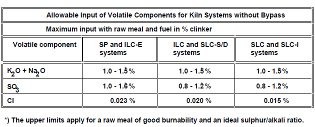
Kiln Bypass System
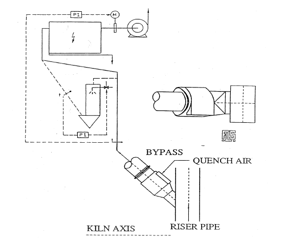
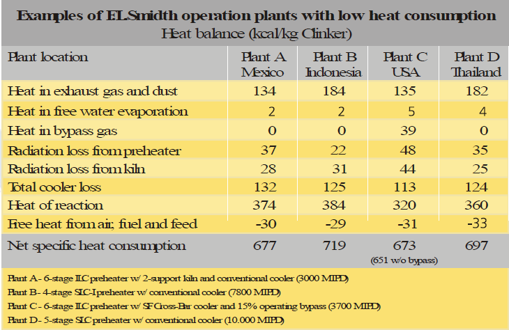
ICPS – Kiln Systems
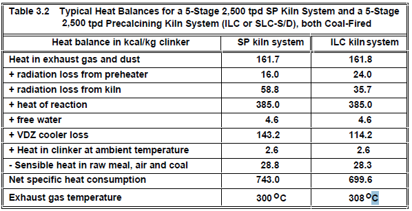
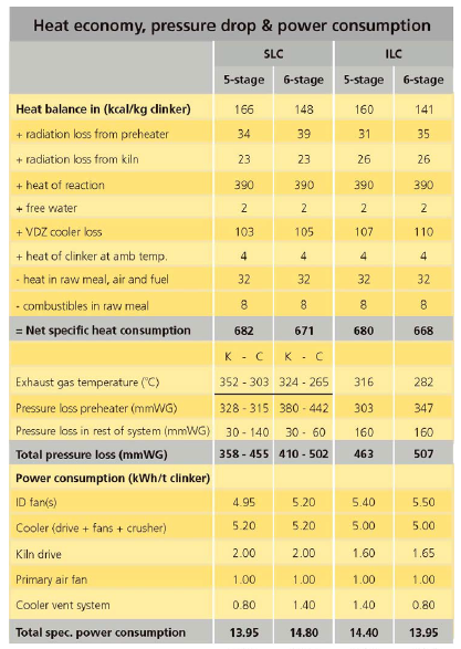
ICPS – Kiln Systems
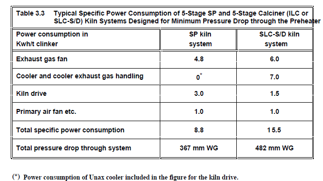
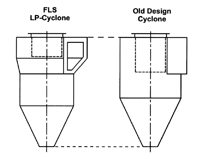
Design of LP Cyclone Types
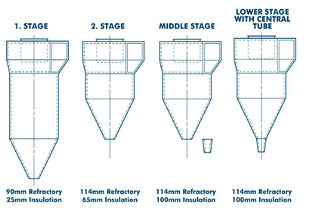
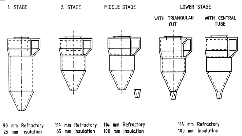
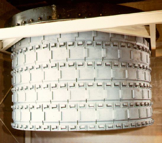
ICPS – Kiln Systems
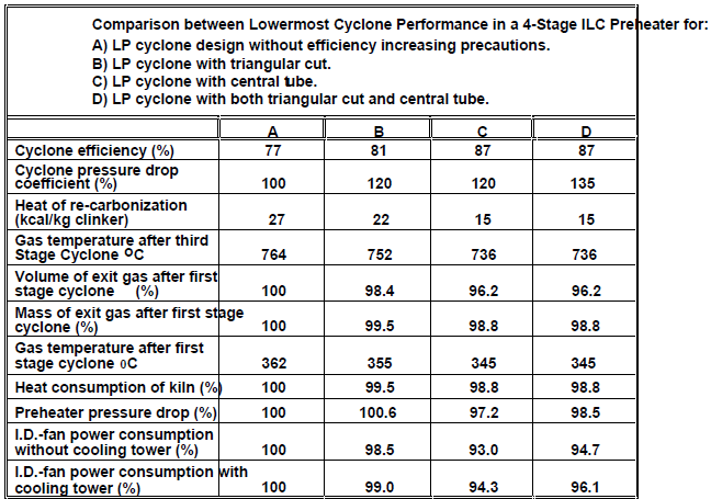
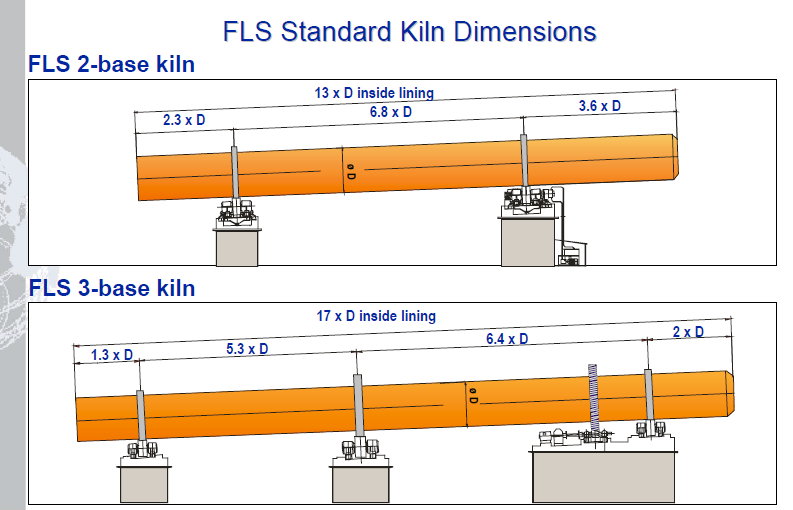
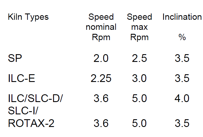
SLC-D – Separate Line Calciner – Downdraft
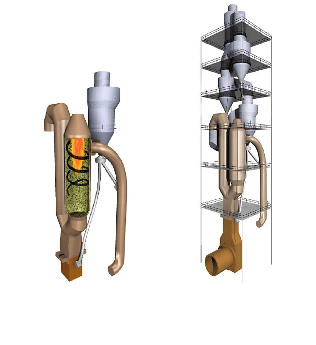
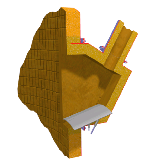
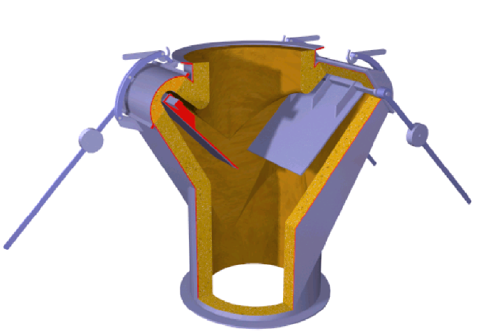
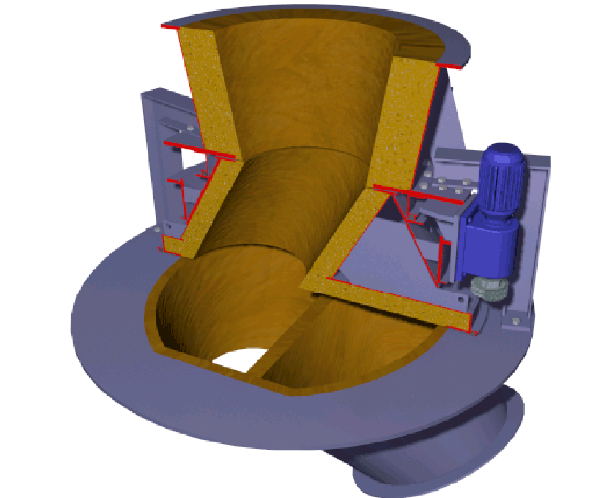
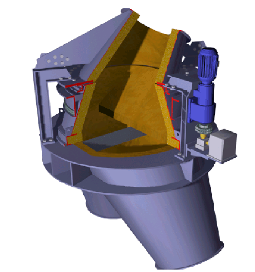
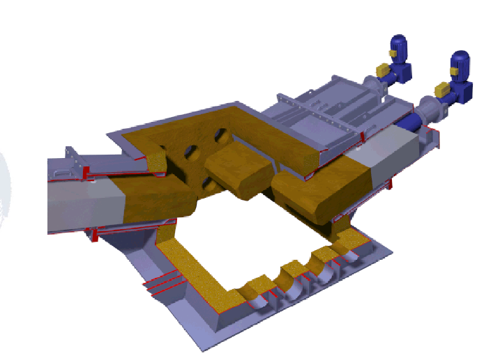
ILC – In-Line Calciner
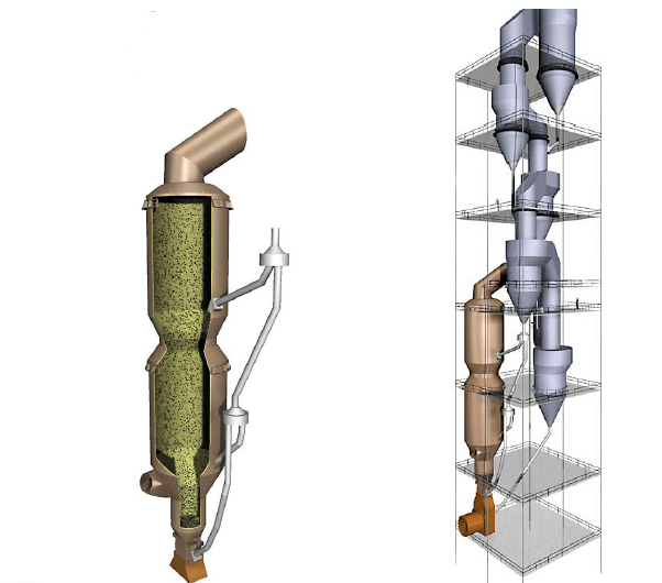
DUOFLEX BURNER
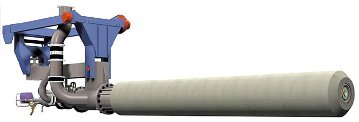
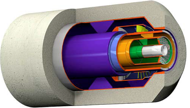
THE (SMIDTH-FULLER) SF CROSS-BAR™ COOLER
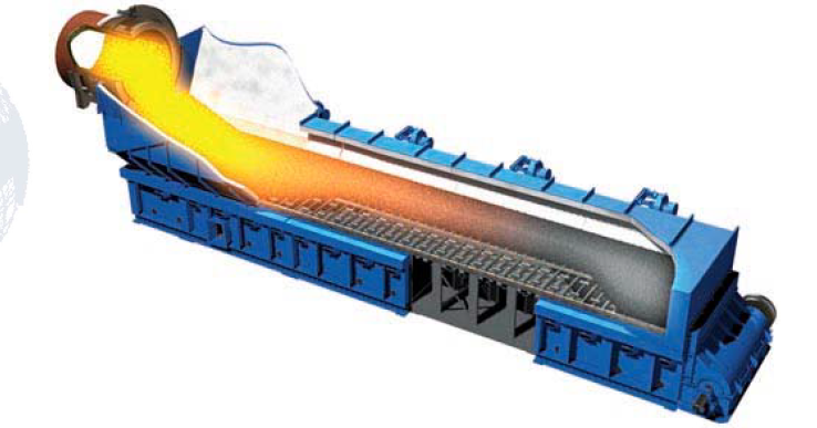
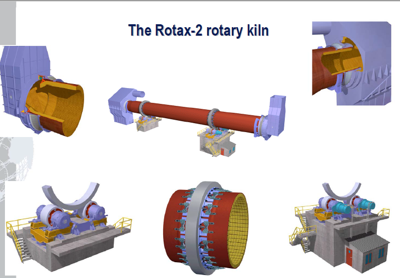
Pneumatic Inlet Seal
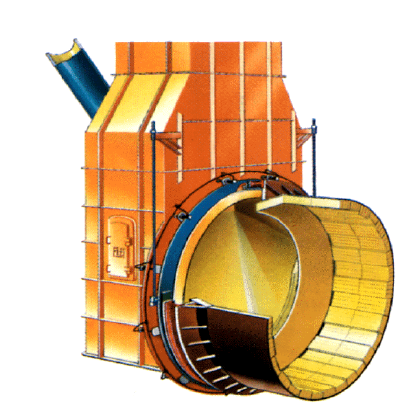
TWO SUPPORT ROTARY KILN
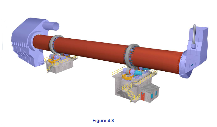
Kiln Drive Through Rollers
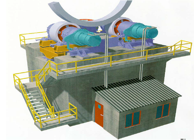
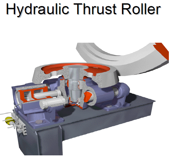
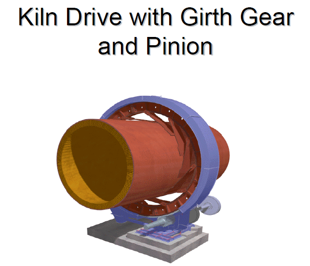
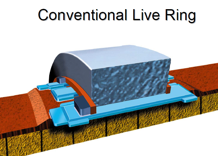
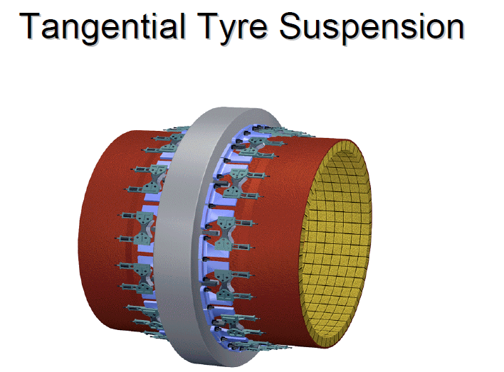
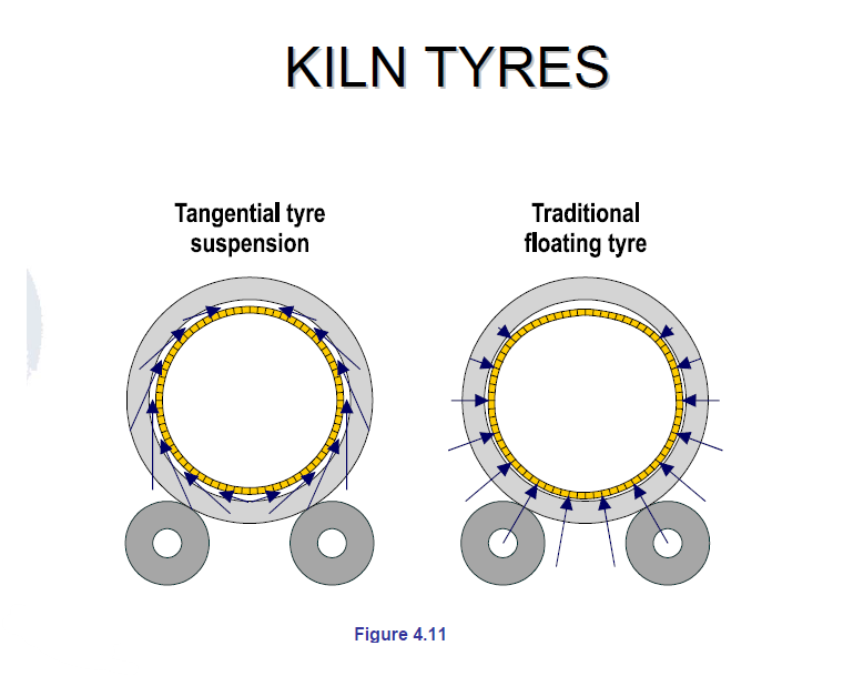
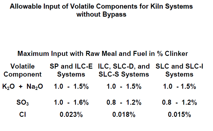
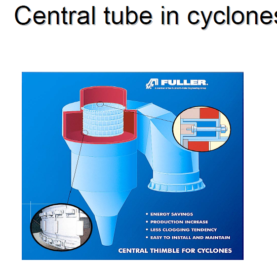
Central Tubes
• Stage 1 : mild steel tube
• Stage 2-3 : heat resistant plate
• Stage 4-5-6 : cast segmented
central tube
• Lowest stage : mat. 25 cr 14 N
Temp. 850°C < t <1100°C
• 2nd lowest stage : mat. 20 cr
Temp. Max. 900°C