Contents
Pneumatic homogenization of raw mix
In the past, the wet process was preferred for the production of high quality cement, since homogenization of the slurry resulted in a thorough mixture of the raw material components. Progress in the fields of aerodynamics and pneumatics has enabled the cement industry to pneumatically homogenize the dry cement raw mix [164]. By this means, the dry process yield’s the same homogeneity of raw mix as the wet production process. This circumstance together with lower heat consumption has resulted in an increasing preference for the dry cement production process.
IF YOU LIKE OUR POSTS AND WANT TO DOWNLOAD ALL OF THEM OFFLINE & IF YOU ARE INTERESTED IN DOWNLOADING THE MOST IMPORTANT BOOKS IN CEMENT INDUSTRY + ALL THE FORMULAS AND EQUATIONS AND CALCULATIONS SHEETS CLICK HERE TO DOWNLOAD THEM
The basic components of the pneumatic dry blending process are the aeration units placed in the bottoms of blending silos in different patterns. This has led to the development of the various existing homogeniza tion methods.
The essential parts of the aeration units are porous, ceramic plates, permeable to air (see Fig. 17.1.).
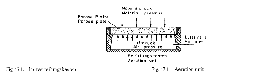
The dimensions of the plates are 250 x 250 mm to
250 x 400 mm, and the thickness is 20- 30 mm. The
diameter of the pores is 70 to 90 microns, consistent with an air permeability rate of approximately
0.5 m3/m2 · min. The flexural strength of the ceramic plates is 40 kg/cm 2, and the compressive strength is 60 kg/cm2. For this purpose also microporous cast
metal plates (sintered metal) of various composition were developed. Further, fabrics consisting of various fibrous material have come into recent usage. Also the use of two-layer ceramic block aeration units has been recently reported [165]. These two-layer blocks can be used without metal boxes; the blocks being inserted into the fresh concrete of the silo bottom. Of course, the two-layer bricks must be connected by pressure air piping.
The air is passed into the raw mix trough the porous plates, where the fine air currents fluidize the raw mix.
The common feature of all homogenization methods is the supplying of air to all areation units mounted on the silo bottom, so that the raw mix is first loos ened, then intensively aerated over only one part of the silo bottom, by means of violent turbulent flow. Depending upon the homogenization methods, the areation area of the bottoms of the blending silos cov ers 55-75 0/o of the total bottom area.
The aeration units are semi-permeable, since the air penetrates the porous plate upwards, whereas when stopping the air flow, the raw mix cannot pass down wards through the plate.
Methods of homogenization
In the past 20 years various raw mix homogenization methods have been developed; these methods are described as follows.
The Fuller Airmerge System
The Fuller Airmerge System, also called the one eight blending method, wherein the aeration units on the silo bottom are combined into eight sections, each of which acts in sequence as the blending section, while the other seven serve as areation sections. Two air compressors supply the aeration and blending air. The volume of the blending air directed into the blending section is 87.5 0/o, and the air directed into the seven aeration sections is 12.5 0/o of the total air. Thus an extremely well aerated light density column of material is created above the blending section. The denser material over the aeration sections contin uously combines with the lighter density material of the blending column, and is displaced upward, thus creating an active vertical circulation of material.
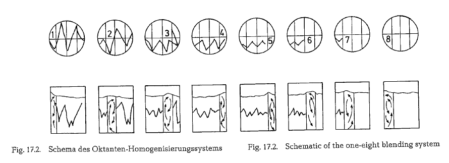
By cycling the air supply to each of the eight sections in turn and at a predetermined length of time, a nearly perfect homogeneous cement raw mix is prod uced; this is diagrammatically shwon in Fig. 12.7. [166].
Under special raw mix quality conditions it might be more advantageous to supply the blending air in pul sations rather than in continuous flow. Pulsated air achieves a higher degree of flowability and a greater mobility of the raw mix with the same amount of air. Pulsation results in a broader and more uniform dis persion of the air throughout the material.
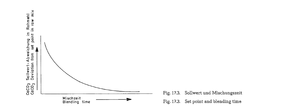
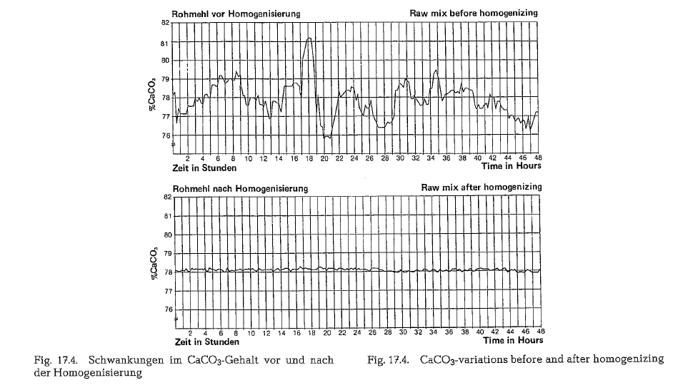
The air and energy requirements for the homogeniza tion of the raw mix, depend upon the variations in the composition of the raw mix entering the blending silo, as well as upon the desired quality set point of the fully blended product. These circumstances extend or reduce the blending time, and conse quently change the air requirements. The connection between the set-point variations in the CaC03-content and the blending time is shown in Fig. 17.3.
At present there is a trend toward extenisive pre homogenization of the raw mix components; this con siderably reduces the raw mix variations in the as-received mixture. Usually the CaC03-content is selected as setpoint for the preparation of the rawmix. With the one-eight homogenization method it is possible to reduce initial CaC03-variations in the raw mix from ± 2 0/o to ± 0.15 0/o, as is diagrammatically shown in Fig. 17.4. [166].
Raw mix adjustment and correction of the silo con tent as e. g. with the application of “high” or “low” raw mix, stipulated by special, local conditions, will not be discussed here.
The air requirement for homogenization is approx imately 10-13m3 per ton of raw mix; in connection with this, the energy requirement per ton of raw mix is 0.65- 0.84 kWh, depending upon the size of the blending silo and its height as well as upon the blend ing time. The pressure of the blending air is approxi mately 2-2.2 kg/cm2, and that of the aeration air approximately 1.75 kg/cm2.
Homogenization of cement raw mix can be performed on a batch basis as well as continuously. For batch type homogenization two blending silos are required. One blending silo may be filled with incoming raw mix, while the content of the other silo is being dis charged into a storage or kiln feed silo. The homogen ization process starts during the filling of the blend ing silo. After filling the blending silo, the homogeni zation process continues for about one hour. The filling time of one blending silo and thus the silo cap acity is approximately equal to 6- 12 hours of raw mill production. When planning new installations, the expected variations in the composition of the raw mix as well as the capacity of the raw mills are taken into consideration. So far the largest blending silo built, has a capacity of 5100 tons of raw mix. The recently initiated arrangement of erecting the blend ing silos on top of the storage silos, considerably reduces the discharge time of the blending silos.
Continuous homogenization can be performed also with only one blending silo. The characteristics of this method depend on the overflow discharge open ing in the wall of the blending silo. Through this over flow opening homogenized raw mix escapes in an amount equal to that displaced by fresh incoming raw mix.
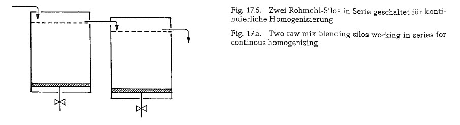
Continuous homogenization can also be performed with two blending silos working in series; this is schematically shown in Fig. 17-.5.
The use of three blending silos working in series is typical of large raw mix quality variations. Under nor mal conditions, three blending silos almost never turn out better homogenization than two blending silos (167-].
Batch type homogenizing is applied in cases where the quality of the raw material widely fluctuates and in relatively long time intervals. Should continuous homogenizing be applied, the quality of the raw material is allowed to fluctuate only within narrow limits and in short periods of time, i. e. continuous homogenizing of the raw mix is best applied in cases where the raw material is already prehomogenized [168].
Aeration blending with the Fuller-one-eight system can be performed in a silo of any diameter, but the height of the silo should be within the limits of 1.0 to 1.5 of its diameter. Sizes of blending silos ·12 m diameter and 17-m height, are not uncommon; the silo size for large capacities is 14m diameter and 18m height. Walls of blending silos made of reinforced concrete are 30- 45 em thick.
Flat bottom silos are preferred, because they provide uniform air distribution. With a sloped bottom, air will escape more freely where the material depth is least; the excessive flow of air through this channel will cause less air to flow in areas where the aeration units are more deeply immersed.
Polysius homogenization systems
The Polysius homogenizing systems are composed of two groups: the discontinuous and the continuous homogenizing.
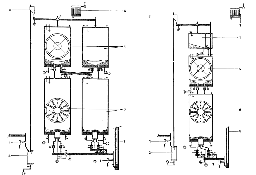
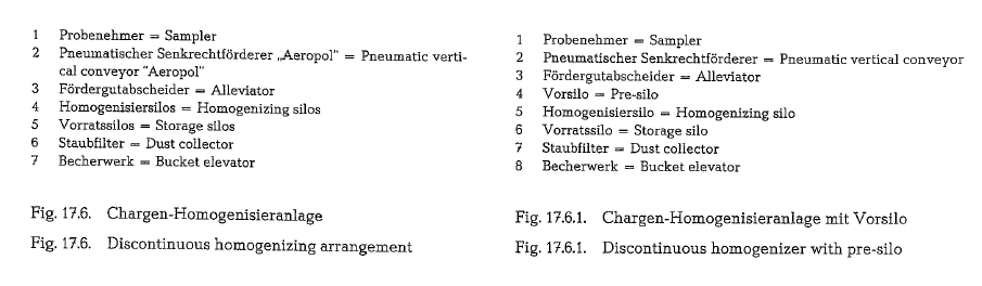
The discontinuous homogenizing system is used to blend the contents of a silo which means that during the homogenizing process no fresh feed is added into the silo, and no discharge takes place. The two types of this system are shown in Fig. 17.6. and 17.6.1.
For batch or discontinuous homogenizing the 1/a or octant system for bottom aeration was developed in 1968. According to the manufacturer this system proved to be advantageous in relation to blending efficiency and power consumption of the 1/4 or quad rant system which was used previously.
For the aeration, the bottom of the silo has a cen tral aeration area and 8 homogenizing sections; the size of these sections is determined by the silo diameter. The aeration intensity is performed in steps. Prin cipally, during the homogenizing process, the central aeration area and two octants facing each other, are simultaneously activated. Blending time depends on the mixing error, and in a predetermined rhythmic cycle the next two sections are activated until all 8 sections have been aerated. Total blending time is between 40 to 60 minutes. This aeration technique allows, in addition to the main vertical turbulence a very effective horizontal mass movement as a secon dary mixing component, which provides t!J.e high degree of homogenization. The two mass movements,ie. vertical and horizontal, are deciding. factors for the efficiency of the 1/s- or octant homogenizing system.
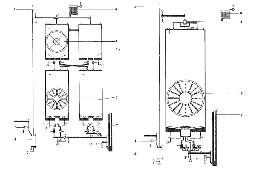
The continuous overflow system (see Fig. 17.6.2.) uses the same partition of the silo bottom, however the operation is not interrupted, allowing overflow of the material. Two aeration sections (the one at the inflow and the other at the outflow) are continuously acti vated, whereas the other sections are active in a rhythmic cycle. This type of silo can also be so modi fied to operate as overflow or as a discontinuous (batch type) homogenizing arrangement respectively.
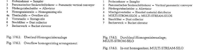
The MULTI-STREAM-SILO (Fig. 17.6.3. and 17.6.4.) is principally an in- and outflow system, and requires, besides the aeration to use the density forces of the material, no further energy for blending. The neces sary intensity for aeration is approximately the same as required for silo discharge.
The periodical feeding of the central chamber is the requirement for the necessary intensity of the mater ial movement within the vertical turbulence area. It retains at all time a sufficient quantity of good flui dized material to feed the kiln system.
The in- and outflow system as a MULTI-STREAM SILO can be used not only as a single silo but also as two silos working in parallel.
The deciding criteria to install one or two silos will depend on first cost, storage capacity, and on the required mixing intensity.
A quasi continuous system represents the in- and outflow homogenization, having pre-storage bins as shown in Fig. 17.6.5. This installation has two silo lev els. The upper level has 7 storage bins of a capacity for 8 to 10 hours of mill operation to store the mater ial of fluctuating composition.
The storage bins are filled one after another and, after the last bin is filled, they are emptied simultaneously. The material from all 7 bins flows into a material dis tributor, located between the silo levels. Cutting the material stream from the 7 bins in the restricted area of the distributor, and feeding it at several points in the lower storage silo, a turbulent mixing is achieved.
In the lower storage silo the different charges from the 7 storage bins are further blended in a continuous homogenizing process.
Fig. 17.6.-17.6.5. are from Krupp Polysius.
SKET/ZAB Homogenizing system (of the SKET Zement-Anlagen-Bau Co., Dessau, German Democratic Republic)
Depending on the chemistry of the raw materials, SKET/ZAB manufactures the following homogeniz ing systems:
– pneumatic homogenizing (batch-type or contin- uous operation)
– discharge homogenizing
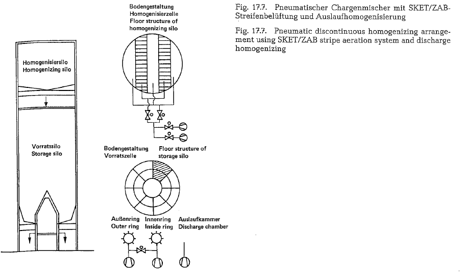
Fig. 17.7. shows a pneumatic homogenizing discontin uous mixing and a storage silo in piggyback construc tion. The upper homogenizing silo operates according to the SKET/ZAB mixing stripe system. The installed aeration pads from stripes across the silo floor; the stripes are alternately aerated, whereas the lower storage silo is equipped with a conically shaped silo floor around which aeration pads are placed in ring form. These rings are divided in eight sections.
To assure a continuous material flow from the silo, the area below the displacement body is also equipped with aeration pads which are continuously operated during material discharge. An equalization factor of 8 to 12 is possible, and the total specific power consumption is between 1.1 to 1.6 t kWh/t (metric).
equipped with aeration pads which are continuously operated during material discharge. An equalization factor of 8 to 12 is possible, and the total specific power consumption is between 1.1 to 1.6 t kWh/t (metric).
With the so-called discharge homogenizing system, when homogenizing and storage takes place in one silo, an equalization factor of 4 to 6 can be achieved, and the total specific power consumption varies between 0.4 and 0.6 kWh/t (metric).
CF silo ofthe F. L. Smidth Co
FLS have developed a new, continuously operated silo for blending and storage of cement raw mix, called the CF silo (Controlled Flow), which extracts the material simultaneously at different rates from a number of outlets in the silo bottom. The new system, incorporating kiln feed equipment, ensures stable kiln feed composition with minimum power consumption and investment costs for blending and storage.
The CF silo is a continuously operating blending and storage plant for raw mix which is used in the pro duction of cement.
In order to achieve a high degree of homogeneity in a continuously operating flow-through silo without air agitation, two conditions must be met:
- All the raw mix in the silo must be kept in constant movement towards the outlet
- The raw mix passing the silo must have different residence times.
This is attained by the operating principle of the CF silo, which extracts raw mix at different rates from several points in the silo bottom, and mixes the streams from the various outlets. This in fact divides the silo into a number of flow streams which operate in parallel at different flow rates, this process being followed by final blending in a small aerated kiln feed or blending bin. A kiln feed with stable chemical composition is thus obtained. The CF silo is provided with a programable control unit for its extraction equipment.
Description
The design of the silo, as shown in Fig. 17.8. is basi cally the same for the various silo diameters ranging from 14m to 31.5 m.
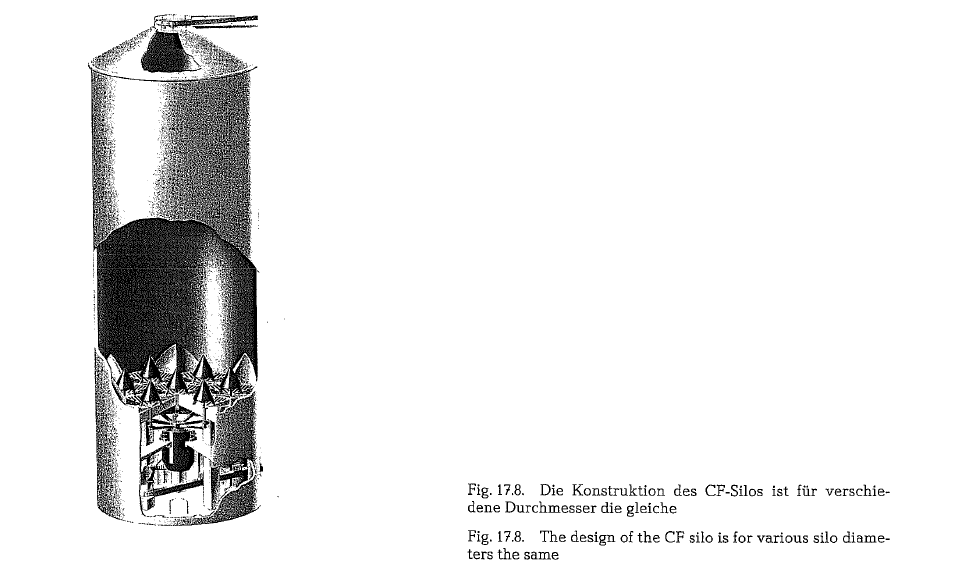
The raised bottom is supported on six main columns, and the kiln feed or blending tank is positioned underneath. The silo bottom is provided with seven extraction outlets.
The material is continuously supplied to silo. The top deck of the silo is equipped with standard features including a manhole, over- and underpressure valves, and level indicators.
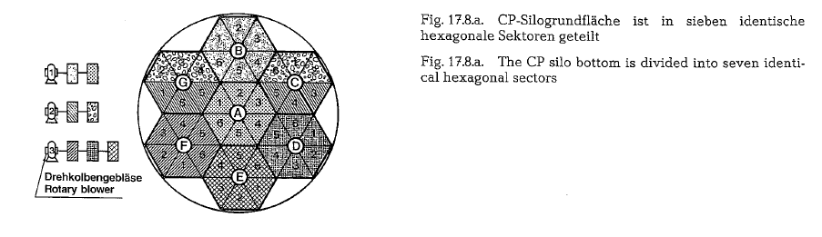
As shown in Fig. 17.8.a. the silo bottom is divided into seven identical hexagonal sectors.
At the center of each hexagonal sector an outlet opening is located, supplied with a conical steel cover. These steel cones are designed to reduce the pressure above the outlets, and to ensure extraction from the aerated part of the silo bottom.
Each of these sectors is divided into six triangular subsectors. Thus, the bottom consists of a total of 42 subsectors, all of which are provided with aeration units. These 42 separate subsectors represent 42 indi vidual areas from which the material can be extracted according to a predetermined program. The fact that the material sinks faster around the base of the outlet cones than in adjacent areas results in additional differentiation of the sinking velocity,
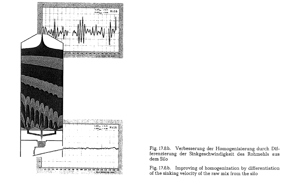
which further improves the homogenization process (see Fig. 17.8.b.). From the extraction outlets the raw mix is led via proper conveying arrangements to the kiln feed bin, which is mounted on load cells.
In actual operation homogenization is performed by using three of the seven discharge outlets simulta neously, each blower aerating only one subsector at a time. This distribution results in low power consump tion. According to F. L. Smidth the specific power_ consumption of a silo for a clinker production of 2500 t/day amounts to about 0.2 kWh/t of raw mix.
The CF silo control is effected via a locally installed control cabinet with a PC (Programable Controller). The sequence of extraction from the seven outlets, the opening of the flap valves, and the aeration of each subsector is programed by the PC.
The different flow rates from the outlets are achieved by varying the opening times of the flap valves, and by varying the discharge rate of the raw mix through each flop valve.
Moller homogenizing processes
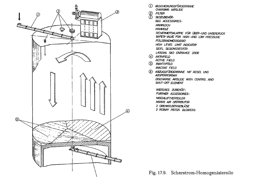
This process is used in applications with large input variations of the CaC03-content (approximately±5 %). The silo bottom is devided into four aeration fields. For a given period of time, only one field is aer ated with a strong stream of air (active air); the three remaining fields are less vigorously aerated (inactive air). This produces a turbulent upward current of air and cement raw mix, while at the same time a down ward shearing current is generated above the remain ing fields (see Fig. 17.9. and 17.10.).
The mixing time depends among others on the pro perties of the material, the size of the blending silo, and on the volume and pressure of the blending air.
In many cases the homogenizing silo is located on top of the storage silo, which enables a gravity discharge of the homogenized raw mix, directly into the storage silo.
For this homogenizing process, the manufacturer quotes the following advantages ( +) and disadvan tages (-}:
+ Large input variations allowed (±5 %)
+ Output variations are small
Relatively high construction cost
Relatively high power requirement
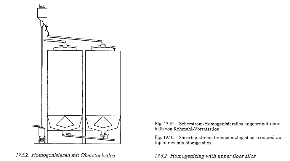
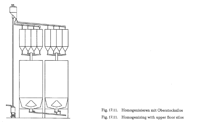
Homogenizing with upper floor silos
This process is used if the raw mix leaving the raw mill shows only small quality variations (approxi mately ± 1.5 %). In such cases usually prehomogenization of the raw material components is applied. In this case several silo cells are located on top of a large storage silo. These silo cells are consecutively filled, applying the silo overflow method. After the silo cells are filled, all discharge gates open simulta neously. After passing air trough conveyors or inclined chutes, the raw mix is accumulated in a cen trally arranged collecting container. Here, the incom ing components are blended, without the help of an additional power supply. From the collecting con tainer, the raw mix is directly discharged into the storage silo (see Fig. 17.11.).
Advantages and disadvantages of this method are:
+ Low power requirements
+ Decrease of output variations by approx. factor 5
Low input variations are required
Relatively high construction cost
Throughput homogenizing in a cone-compartment silo
This process can be used only for a cement raw mix with narrow input variations (about ± 1 %). In this case, prehomogenizing of the raw material components is a prerequisite.
The raw mix is conveyed into a distribution basin. This container is supplied with radially arranged pneumatic trough conveyors (distribution spider). Supply of fluidizing air to the pneumatic trough con veyors comes from a rotating air distributor, so that the material is consecutively distributed over the total silo cross-section; this is the first step of raw mix blending.
For optimization of the velocity profile, and of the aeration surface, the lower part of the silo is conically shaped. The total remaining ground floor is furnished with aeration troughs. During silo discharge, these troughs are consecutively aerated on a revolving sequence (see Fig. 17.12. and 17.13.). The second blending of the raw mix occurs during passage through the silo. Filling and discharge of the silo are timed according to an adjustable cycle, which, at any given time is displaced by 180 angular degrees [170).
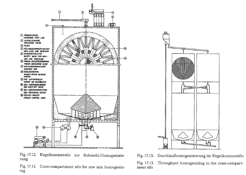
The conception of the throughput blending allows for a reduction of the silo capacity by about 40-50 %, as compared to the processes described under items 17.5.1. and 17.5.2., since the storage silo is simultaneously used also as a blending silo.
Advantages and disadvantages of this process are:
+ Considerable reduction of construction costs
+ Low power requirement
+ Decrease of output variations by factor 5-10
Low input variations are a prerequisite
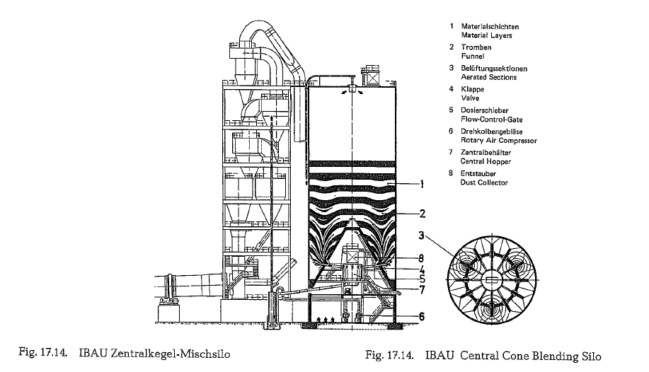
The IBAU-Central cone-system(IBAU HAMBURG/WEST GERMANY)
The blending silo is simultaneously used for a contin uous blending process as well as for raw mix storage (see Fig. 17.14.)
The feeding of the silo takes place via a novel type of distributor cone ensuring a controlled build-up of the different material layers.
Homogenizing the raw mix i. e., blending the respec tive layers (1), is achieved by causing the layers of dif ferent CaC03 content to flow together by funneling action and thus merging with one The gravity flow in the funnels produces the blending effect.
The bottom of the silo is divided into aeration sec tions (3).
Each section has a flow control gate (5) and an air valve (4) assigned to it. Three blowers (6), each of 6 KW rating are available for aerating the silo bottom. The sections are aerated three at a time for varying periods. As a result, three funnels are formed simulta neously, developing relatively slowly from the silo bottom to the upper surface of the stored material. This funnel formation process is so controlled, that fresh raw mix which has just been fed into the silo cannot rush straight through to the silo outlet. This being prevented by first closing the three gates of the aerated sections and causing three new funnels to develop in three other sections. This ensures con trolled flow behaviour of the blending funnels, which is essential to good blending performance.
The power consumption amounts to 0.1- 0.3 KWh/t (metric) of raw mix.
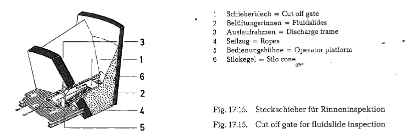
Each of the aeration sections (Fig. 17.15.), which are designed as simple fluidslides {2), can be closed by means of a cut-off gate (1) located at the discharge fra.tne (3).
This is an entirely novel system in that exchange (replacement) of the aeration sections can be done while the plant is in operation. The cut-off gate ensures that no raw mix can enter the aeration sec tions during repairs or inspections. Thanks to these arrangements, an otherwise needed stand by silo can be dispensed, since the blending/homogenizing func tion can continue undisturbed even while repairs are in progress.
Hence it is no longer necessary to empty the silo for checking or repairing the aeration units in the interior.
The filter (8) on the central bin (Fig. 17.14.) prevents any dust nuisance arising from the plant in operation. The aeration system installed in the cone, with eight to ten air changes per hour, provides good operating and servicing conditions. All the items of equipment, including the aeration sections in the interior of the silo, are so arranged under the cone that they are eas ily and safely accessible to attendant personnel.
The raw mix homogenized for CaC03 content is fed through closed airslides to a weigh hopper (7) installed centrally under the cone in the silo. The hopper is supported on three load cells which are integrated in the DICONT* system.
The raw mix required·for continuous kiln operation is fed through a flow control gate which is controlled by the DICONT system: The mix is supplied to the IBAU air lift through pneumatic conveyors.
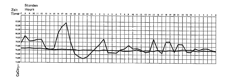
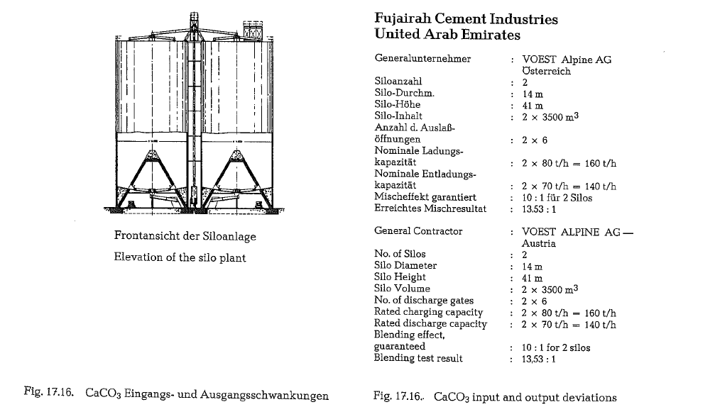
The blending ratio for one silo is 7 : 1, for two silos in parallel operation 10 : 1 and for three silos in parallel operation 15 : 1.
The working principle of the DICONT 031 is based on the differentiation method. Conveying rate per mea sured unit has to be equal to the “time” set value.
The system components are the weigh hopper with adjustable flow control gate and the DICONT 031 in accordonance with the silo discharge control system.
The weigh hopper is filled up to a maximum value and than discharged to a minimum value. Weight dif ference between max. and min. has to be compen sated by feeding into the hopper in the time limit set by the set point. During hopper feeding, the convey ing capacity will be kept constant.
Weighing hopper content is measured via load cells, 0- 100 % filling is converted into unit signals 0.4- 20 rnA. The discharge rate is controlled via flow control gate. A precision potentiometer with an ohm/ampere transducer measures the flow control gate position, 0-100% opening equal 0.4-20 rnA unit signals.
The regulating process takes place in two steps:
- regulating phase
- adaption phase
According to a recent license agreement, Fuller Co. of Bethlehem, Pa., builds now IBAU-type silos in USA. Canada and Mexico.
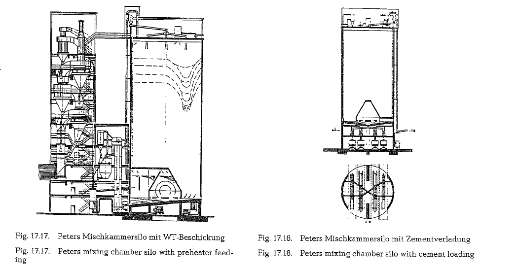
Peters mixing chamber silo process (Claudius Peters Co., Hamburg,
Extensive experience gained with quadrant homo genizing silos and with pneumatic discharge systems of storage silos, resulted in the development of new types of blending silos.
The mixing chamber process is a continuous process, blending the raw mix simultaneously during silo feeding and discharge, or only when the material is discharged from the silo.
Another function of the mixing chamber silo station is to store or buffer material, to compensate for acci dental or planned shutdowns of preceding installa tions. Radially arranged air trough conveyors cover ing the flat silo bottom, are divided into aeration sections.
The bottom center covered by a vented mixing cham ber is pressure relieved against the main silo com partment. The blending process starts when the material is fed into the silo. Flowing through a paral lel distributor, connected to fan shaped air trough conveyors, the raw mix forms horizontal layers.
Low pressure air is admitted to a section of the peri pheral silo ring. This partial aeration creates a flui dized material layer that passes underneath the unaerated material load, through peripheral open ings, into the mixing chamber, where it freely expands. Any excess air is vented within the silo. These conditions permit to aerate the next material layer above the peripheral silo ring up to the shell zone, and to complete a material flow over the entire silo cross-section. Alternated sectional aeration ini tiates a gravity preblending inside the main silo com partment, supported by the bulk material load and its frictional characteristics.
The preblended material entering the mixing cham ber is subjected to an intensive, alternated aeration, fluidizing the material layers, and thus effecting an active blending, as is schematically shown in Fig.17.17 and 17.18.
Generally, the minimum capacity of a silo arrange ment should last for a two or three days” supply of raw mix. The optimum ratio between silo diameter and maximum filling height is approximately 1:1.5 to 1:2.
Peters mixing chamber silos are constructed as one story silos. The particular design permits material dis charge, at a controlled rate, through only one lateral discharge socket located in the silo wall, irrespective of the silo diameter. With elevated silo bottoms material discharge can also be through the silo bot tom. If several connections are necessary, additional silo discharge spouts can be provided at silo bottom as well as silo walls. Silo utilization is 98 %. The spe cific power requirement for continuous blending and discharge is quoted to be 0.2- 0.4 kWh/t.

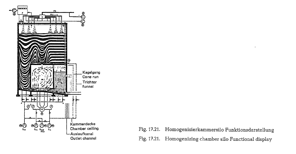
Peters homogenizing chamber silo process
The homogenizing chamber silo as shown in Fig.
17.21. is a Claudius Peters AG development, and is
used in combination to modify long lasting fluctua tions and to store powdered material. According to the manufacturer, continuous through-flow is enhanced by using the four blending principles:
- Reduction of mass-flow through separation during silo-feeding
- Gravity blending in the main silo area with a con trolled funnel-flow
- Intermittant blending of the central material col umn by divergence into a chamber
- Pneumatic quadrant homogenizing in the inte grated and aerated homogenizing chamber.
With this type of silo, blending factors of Ms 15 : 1 can be achieved.
Silo construction cost analysis
Silos differentiate essentially by discharge and/or shape of bottoms. Construction costs of the silo unit itself are greater than those of the mechanical equipment.
Investment costs of the silo unit are largely depend ing on the kind of discharge structure between silo bottom and foundation, as well as the shape of the silo bottom and/or the kind of construction. Another cost factor is the local requirement under which the silo system is to be erected and also the quest for building a functional silo concept applying an opti mum execution of construction work.
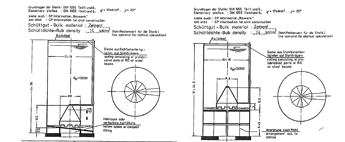
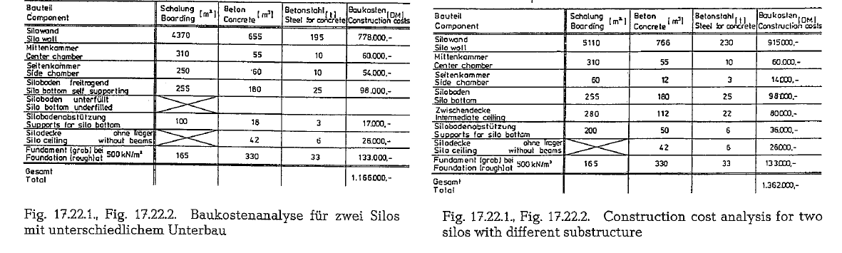
A comparison of two large silos, each with 12,000 t of usable contents with an average density of 14 kN/m3 each, is prepared in regards to construction costs and cost analysis- built in West Germany- as shown in Fig. 17.22.1. and 17.22.2. [170 a].