Contents
Prehomogenization
In past cases, where the main component of the cement raw material (usually limestone), showed con siderable fluctuations in the CaC03-content, and as long as relatively low quantities of raw materials were processed in cement plants, selective quarrying was applied, to reduce to some extent fluctuations in the limestone’s chemistry. With increasing produc tion capacity of the cement plants, selective quarry ing became uneconomical, and therefore, the cement industry was looking for other methods for the pre homogenization of cement raw material components. These methods of raw material prehomogenization were already known and applied since 1905 in the ore dressing as well as in other industries, before they were employed in the cement industry.
IF YOU LIKE OUR POSTS AND WANT TO DOWNLOAD ALL OF THEM OFFLINE & IF YOU ARE INTERESTED IN DOWNLOADING THE MOST IMPORTANT BOOKS IN CEMENT INDUSTRY + ALL THE FORMULAS AND EQUATIONS AND CALCULATIONS SHEETS CLICK HERE TO DOWNLOAD THEM
Prehomogenization is mostly applied to the main component of the cement raw material, namely the limestone. The argillaceous component is pedomi nantly homogeneous, although many cement plants have to prehomogenize also this component. Such raw material components as silica sand and iron ore are almost always homogeneous, and do not require prehomogenization. In cases where granulated high furnace slag is employed in the process of cement manufacture, it is useful to prehomogenize also this component.
Methods of prehomogenization
Prehomogenization can be divided into two groups:
- Combined prehomogenization of the raw material components
- Segregated prehomogenization of the particular raw material components
Combined prehomogenization of raw material com ponents requires components of balanced chemical composition. The proportioning of the components is performed before stacking the stockpile. Irregular particle size composition of the components, how ever, can cause partial segregation, resulting in tem porary chemical deviation of the raw mix from the set point. This method which is not much in use, does not yield such high quality results as prehomogeniza tion of the particular components.
Segregated prehomogenization of the raw material components is the most applied method of preblend ing in the cement industry. According to the pro jected chemical composition of the raw mix (calcula tion of the raw mix composition see chapter 2), the particular prehomogenized components, after propor tioning them via feed bins and weigh feeders, are fedinto the raw grinding mill. The chemical analysis of the raw mix leaving the raw mill, supplies informa tion as to what corrective measures should be taken.
Crushed material with a particle size of up to 1 inch, is used for stockpiling the blending beds. The quality of the blending bed depends on the method of stock piling. Usually, the stacking of blending beds is per formed along a longitudinal axis (longitudinal stock piles), whereas reclaiming of the stockpile is com pleted in the transverse direction, i.e. by cross-cut ting. With no sufficient space available, blending beds can be erected in a circular way (circular or round stockpiles). However, investment costs of circular stockpiles are about 30- 40 % higher than that of comparable lonitudinal stockpiles.
- Stacking of blending beds
- Longitudinal stockpiles
The following stockpiling methods of blending beds are employed:
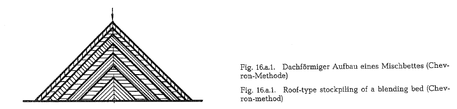
- Roof-type stockpiles (Chevron-method)
The most frequently employed blending bed is the roof-type structure of the stockpile. The material is piled up in individual layers along the total length of the blending bed, as is shown in Fig. 16.a.l.
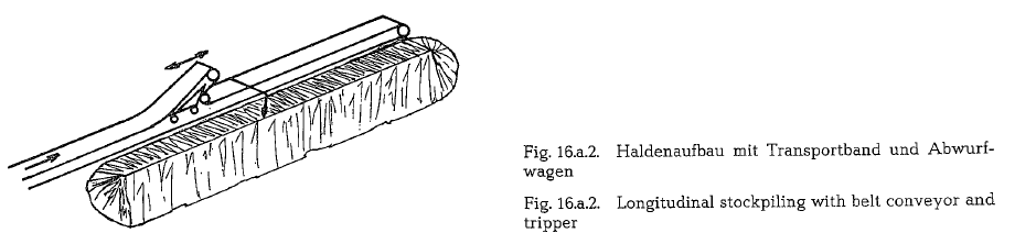
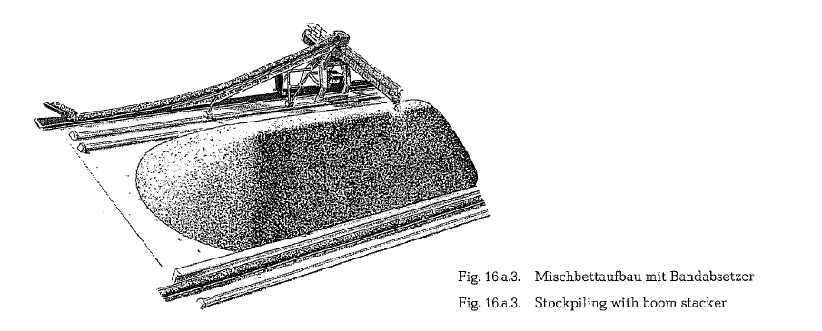
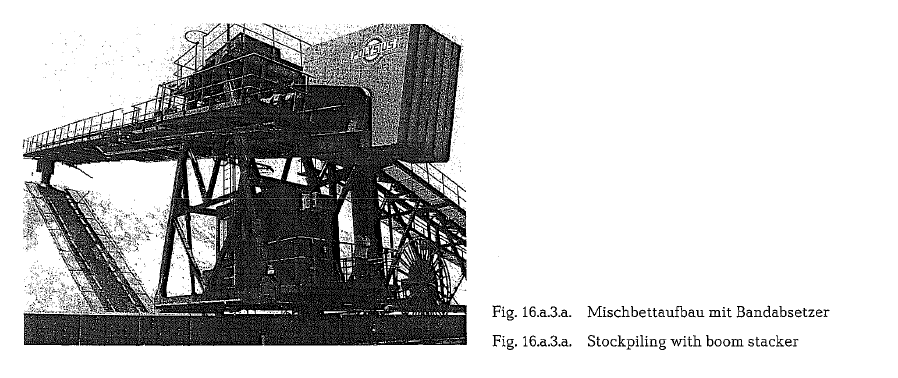
Stockpiling of a blending bed is performed either by a belt conveyor with tripper (see Fig. 16.a.2.), or by a stacker with a rigid boom, which moves alongside the stockpile (see Fig. 16.a.3. and 16.a.3.a.). With this method of stockpiling, the particular material layers are roof-shaped and deposited one upon the other.
The stockpiling is simple, since only one discharge point is used along the length of the blending bed. Theoretically, the moving speed of the stacker should be controlled in order to obtain the required thickness of the material layers. However, practical exper ience has proved that uniform stockpile is built up even without such a speed-control system, because the fluctuations in the material feed quantity are ran domly distributed. If the material particles are une qually sized, it can happen that with this method the coarser particles roll down on the slope to the base of the blending bed, thus causing an accumulation of coarse particles in this area.
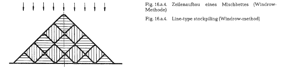
- Line-type stacking (Windrow-method)To avoid the disadvantage of coarse particle accumulation or particle size segregation, the Windrow method of stockpiling is sometimes selected (see Fig. 16.a.4.).
This type of blending bed is characterized by distri buting the material layers in the form of longitudinal stripes, side by side, and one upon another, so that the coarse particles have little chance to segregate. The particle size difference decreases with increasing numbers of material lines. However, this method of stockpiling requires more expensive and transferable belt stackers, since a row of piling positions are required for this purpose (see arrows in Fig. 16.a.4.).
Where blending is concerned however, there is no practical difference between the Windrow and the Chevron method.
There exists, additionally, a series of other stockpil ing methods of blending beds, namely:
- Areal stockpiling (Fig. a.5.)
- Axial stockpiling (Fig. a.6.)
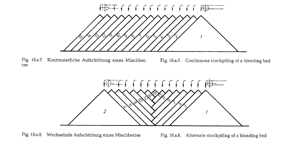
- Continuous stockpiling (Fig. a.7.)
- Alternate stockpiling (Fig. a.8.)
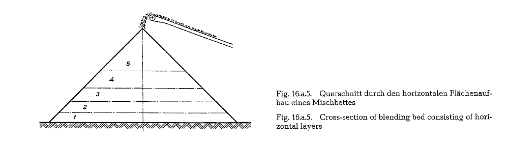
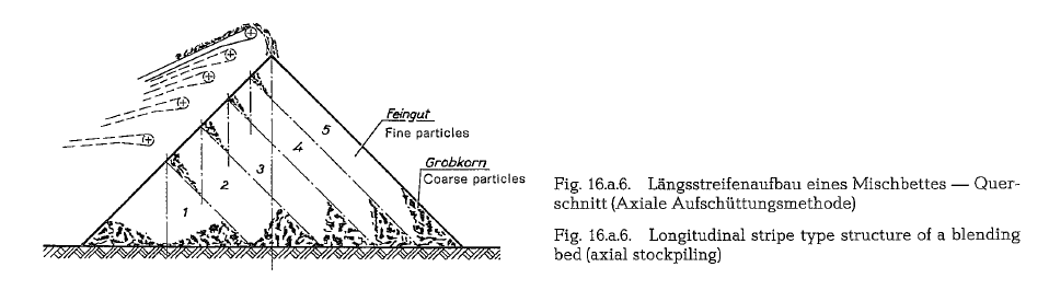
The stockpiling methods quoted under items 3- 6, are selected or recommended according to local quality conditions of the raw materials with the assumption that one or the other method may result in better blending effects.
Generally, it can be said that these methods due to their low blending effect are in limited use.
Circular blending beds
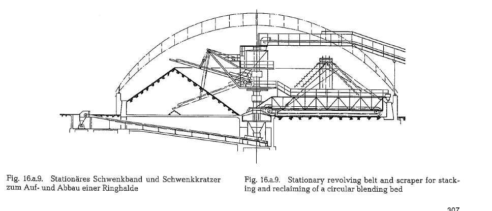
The stockpiling of a circular blending bed is per formed by a belt conveyor which is swivel-mounted in the bed”s center point (Fig. 16.a.9.). The cross-sec tion of a circular stockpile can be either triangular or trapezoidaL The most used stockpiling methods for circular blending beds are the Chevron-method, the Windrow-method, and the bed structure with hori zontal layers. Circular blending beds with Windrow structure show that the diameter of the outer rows is larger than that of the inner ones, which, in certain cases, can disadvantageously influence the blending.
Regular supply of the material from the crusher to the blending bed results in equal dimensions of the layers, stripes, or strata, and thus, each cross-section of the stockpile represents an average or equalized quality of the materiaL
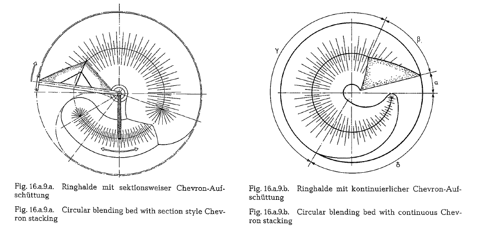
In most of the cases circular blending beds are being stacked according to the Chevron method; the Win drow method is applied only in rare cases. Circular blending beds employ basically two different forms of Chevron stacking, namely: Section-style Chevron stacking, and Continuous Chevron stacking.
Fig. 16.a.9.a. shows a circular blending bed with sec tion-style Chevron stacking (F. L. Smidth).
Stacking is relatively straightforward and can be compared to longitudinal blending beds.
However, this method produces substantial chemical variations in the transitional zones from one section to another. The smaller the circular blending bed the greater the problem, due to increased frequency with which it occurs.
Continuous Chevron stacking is the most common method today applied in circular blending beds (Fig.
16.a.9.b. F. L. Smidth). Compared with section-type
Chevron stacking, this method has the following advantages:
- Provides a larger volume of fully homogenized stored material at the same diameter of the blend ing bed.
- Completely continuous stacking, and therefore no waiting for opening of new
- The stacking zone is infinitely variable to satisfy blending
- No transition zones and resultant fluctuations in the chemical
- Maximum storage capability at all times, resulting in greater operating
Reclaiming of stockpiles
The following equipment is mostly in use for reclaim ing of stockpiles:
Reclaiming scraper , Reclaiming bucket, wheel Disc reclaimer
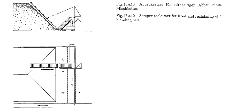
In most cases, the stockpiles are reclaimed from the front end in disk-shaped portions. Each reclaimed material disk or slice, is equivalent to the average quality of the blending bed.
The reclaiming scraper consists of the boom supplied with the circulating chain furnished with scrapers. The construction of the scraping boom allows for lift ing, lowering, and revolving movements. Depending on the type of design, the scraper can reclaim the blending bed from the front end, or by traveling along and adjacent to the longitudinal axis of the stockpile. Belt conveyors then convey the reclaimed material to the mill feed bins. Fig. 16.a.10. shows a reclaiming scraper for front reclaiming of a blending bed.
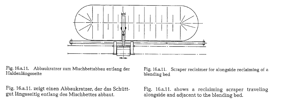
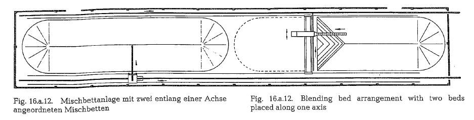
Fig. 16.a.l2. shows a blending bed arrangement with two blending beds located one after another. The stacking is accomplished alongside the bed, whereas reclaiming is carried out from the front end. Contin uous operation of prehomogenization is performed by simultaneously stacking and reclaiming of one of each stockpile. Stacking belt conveyor and reclaiming scraper are capable of moving along both stockpiles.
Fig. 16.a.l2.a. shows a stockpile for additives with stacker and sidescraper (Krupp Polysius AG).
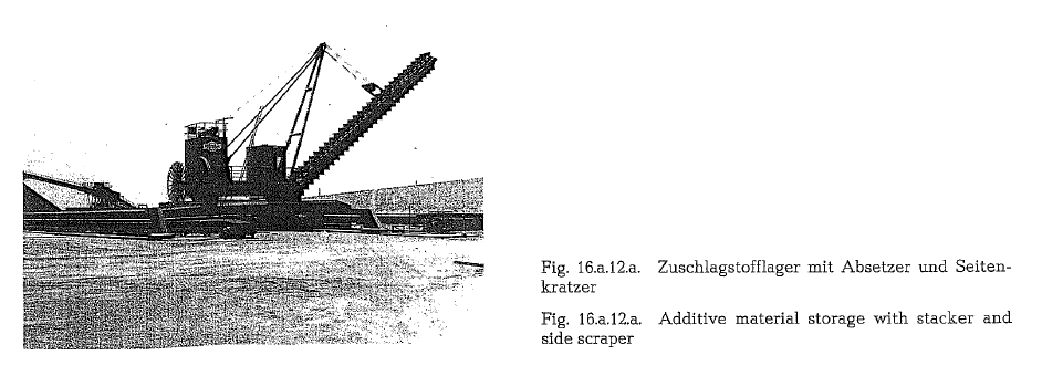
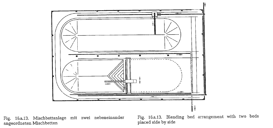
Fig. 16.a.13. shows two blending beds arranged in a parallel position. Here also, stockpiling is performed along the piles, whereas reclaiming is completed from the front end. A transverse track serves for transfer ring the reclaiming scraper from one stockpile to the other.
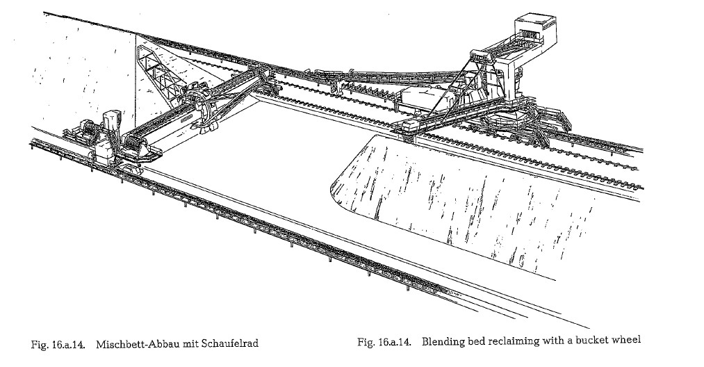
The reclaiming bucket wheel
Fig. 16.a.14. shows the reclaiming method when employing the bucket wheel.
The bridge mounted bucket wheel is designed to simultaneously accomplish a revolving and a trans verse movement. As shown in the picture, the bucket wheel picks up the material from the base of the stockpile. Therefore, this reclaiming arrangement is supplied with a rake, to loosen the upper part of the pile, so that the material rolls down to the bucket wheel.
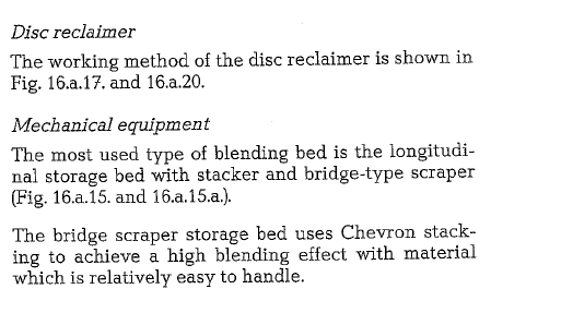
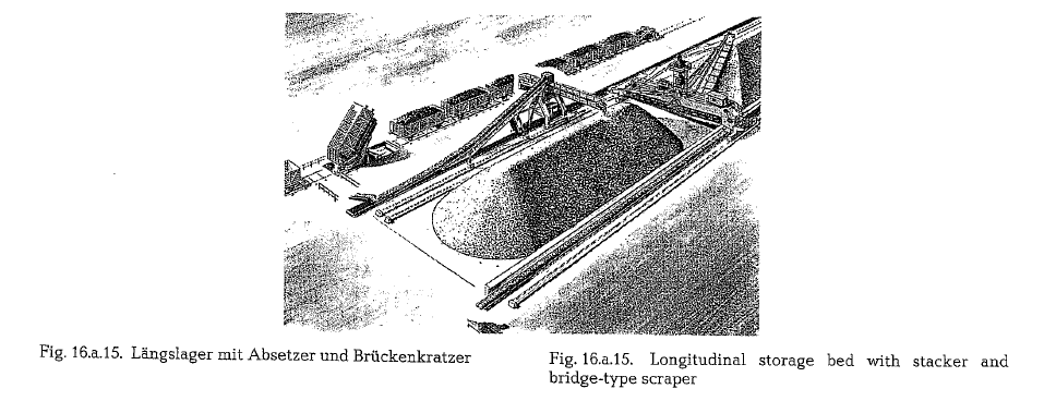
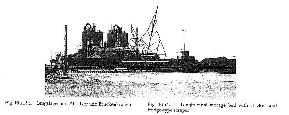
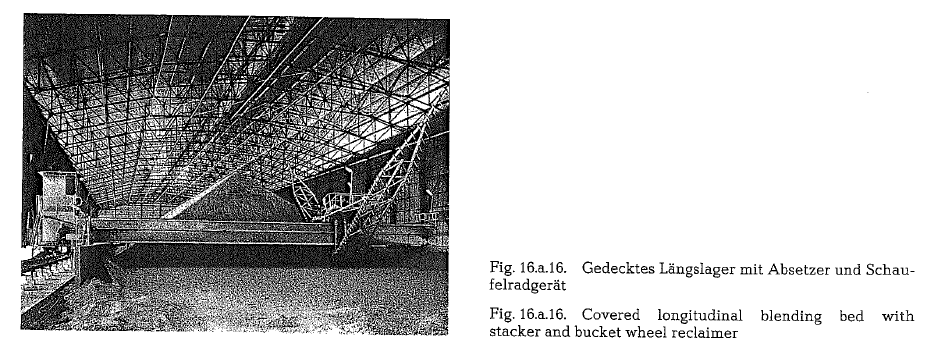
Also much in use is the storage bed equipped with stacker and bucket wheel reclaimer (Fig. 16.a.16.).
The bucket wheel reclaimer is sensitive to sticky material. To maintain a uniform chemical composi tion, and also to avoid segregation of the material, the application of Windrow stacking might be necessary, if a bucket wheel reclaimer is used.
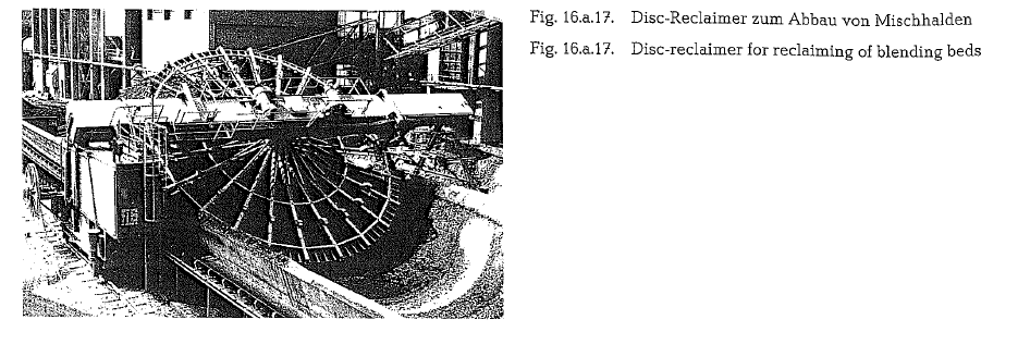
A comparatively new development in reclaiming of blending beds is the Disc-Reclaimer (Fig. 16.a.l7.).
The disc-reclaimer is distinctive in being the only reclaimer on the market, which, during the reclaim ing process is 100 % in contact with the pile’s cross section. This guarantees, according to F. L. Smidth an optimum blending effekt. Furthermore, the disc reclaimer needs less space than a bridge scraper of the same capacity. Besides, maintenance costs are substantially lower.
However, the erection costs and the power consump tion are higher than those of other reclaimer designs.
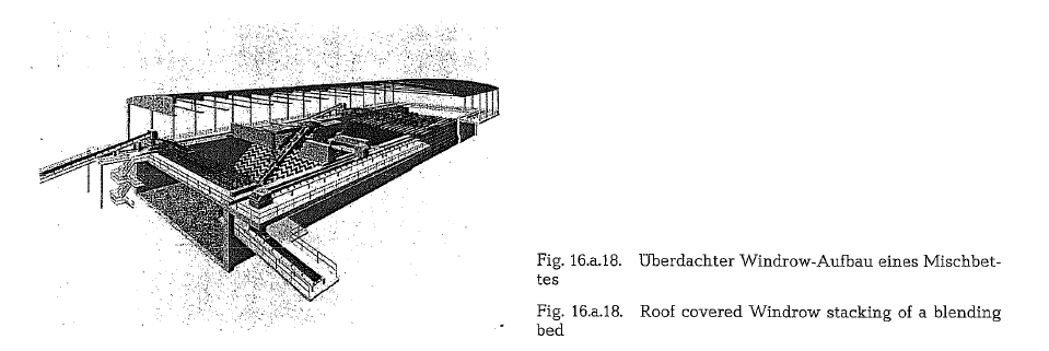
Fig. 16.a.18. shows a raw material storage which, due to lack of space is longitudinally enclosed by walls; atmospheric conditions necessitate the use of a roof. Windrow stacking is the best solution for this design of a blending bed.
Where roofing is not an absolute requirement, the need for supporting walls makes this type of blending bed a relative expensive construction.
The storage capacity of longitudinal blending beds can be easily enlarged, but it must be borne in mind that such an increase in capacity generally requires a corresponding increase in the capacity of the installed machinery, such as stackers, reclaimers and conveying belts. Increasing the capacity of blending beds always involves considerable difficulties and expenses.
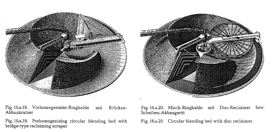
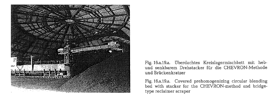
For prehomogenization circular blending beds are increasingly applied. This is partly due to the low cost- the price is 25-30 % lower as roofed longitu dinal blending beds -and to some extent due to the continuity of operation, and also because of the ease with which they can be integrated into existing oper ating conditions, and plant layouts.
The following two pictures show a circular blending bed with a bridge-type reclaiming scraper, and a cir cular blending bed with disc reclaimer.
A disadvantage of circular blending beds is that at a future plant expansion their capacity cannot be enlarged.
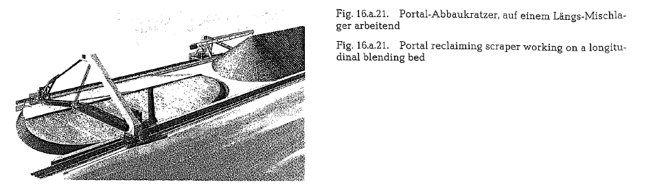
Fig. 16.a.21. shows a portal reclaiming scraper installed on a longitudinal prehomogenizing bed; the working method which can be seen from the picture is self-explanatory. Portal scrapers are available with free spans up to 60 m, and are, when compared with other reclaimers, relatively low in investment cost. Portal reclaiming scrapers can also be applied to cir cular blending beds.
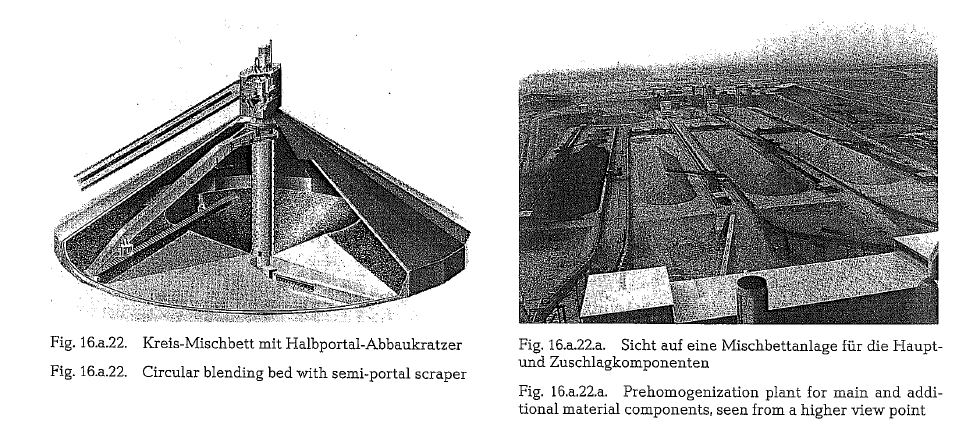
For storage and blending of easy flowing raw mater ial. as well as of clinker, fly-ash, granulated blast-fur nace slag, etc. a new type of circular blending bed equipped with a semi-portal reclaimer may be adwan tageously used. This circular blending bed is shown in Fig. 16.a.22.
At circular blending beds the material enters through the top of the storage construction, and is discharged into a central column, consisting usually of concrete; this column is provided with a multitude of outlets which is shown in the quoted picture. The column design ensures that the discharge is almost dust-free.
About 25 % of the total blending bed is being dis charged due to flowing by force of gravity into a cen trally located vibrating reclaimer, working under neath the bed base. The remaing 75 % of the blending bed is reclaimed by the semi-portal scraper which conveys the material to the crest of the pile, from where, according to the angle of repose, it flows down to the central outlet.
This circular blending bed has the advantage of work ing without leaving dead zones. Besides, at normalsoil conditions, and at capacities of 40,000 t and more, this blending bed is lower in price than similar silos. A silo of this design is described in section 22.8. (Fly- ash silos) of this book.
Fig. 16.a.15. to x1,6.a.22.a: are from F. L. Smidth and Krupp Polysius AG.
Blending effect
With qualitatively controlled stacking of blending beds, initial oscillations of about 10 % in the CaC03- content of the limestone can be reduced to 1.5 % and sometimes even to a lower rate. Then an on-line X-ray analyzer gravimetrically proportions the pre homogenized limestone component together with other raw material components, before feeding the
., material into the raw mill. The raw mix leaving the raw mill then enters the pneumatic raw mix homo genizing silos, where possible remaining oscillations in the chemistry of the raw mix are reduced to one tenth of the entering oscillations.
Sizes of blending beds
Usually, a raw material consumption of 7-10 work ing days is taken into consideration, when estimating the size of blending stockpiles. The height of the stockpiles depends on the angle of repose of the particular raw material, which ultimately leads to the length of the material bed. Special quarry and tran sportation conditions may sometimes require blend ing beds with higher capacities. The length to width ratio of blending beds should be as large as possible at least 3:1. Usually, the outer end cones of theblending beds are not completely reclaimed for cur rent production, to prevent fluctuations in the quality set point of the raw material [163a-163s].
Güzel bir mekale
This is very important topic