Quick answer
Capacitor-bank step hunting—steps repeatedly switching on and off—usually means the power-factor controller is reacting to a marginal setpoint, unstable load, incorrect CT signal, switching delay, failed capacitor step or harmonic condition. Diagnose power factor, kvar demand, step status, CT polarity/ratio, controller target/deadband, switching delay and capacitor current before changing settings. Repeated switching shortens contactor and capacitor life.
Problem / job
Automatic power-factor correction steps chatter or cycle frequently although plant production is relatively steady.
Evidence
Capture power factor, kvar, phase currents, controller step commands, actual capacitor currents, switching interval, CT data and major load changes.
Decision
Separate controller/CT problems from genuine fast load changes, failed steps, contactor issues and harmonic/resonance effects.
As-found evidence capture
Trend power factor and kvar demand together with each capacitor-step command. Identify whether one particular step repeatedly enters and leaves service or whether the whole bank hunts. Compare actual capacitor current after each command with the expected behavior.
Capacitor banks contain hazardous stored energy. Inspection and testing must follow site electrical isolation, discharge verification and qualified-person procedures.
Seven-step diagnostic workflow
1. Confirm the load is actually stable
Large cycling motors, crushers, mills or welders can make legitimate kvar demand move across the controller threshold. If plant load is truly varying, hunting may be a control-band problem rather than a component failure.
2. Verify CT polarity, ratio and location
Incorrect CT orientation, phase reference or ratio can make the regulator calculate reactive power incorrectly. Review wiring against the approved scheme before changing the target power factor.
3. Review target, deadband and switching delay
A very tight target/deadband or short switching delay can make the controller reverse decisions repeatedly near the threshold. Compare with the controller/OEM design settings.
4. Verify each capacitor step actually delivers kvar
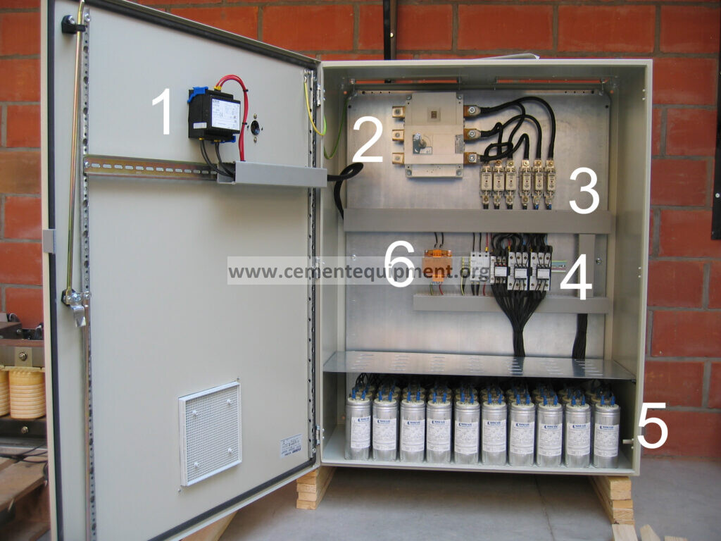
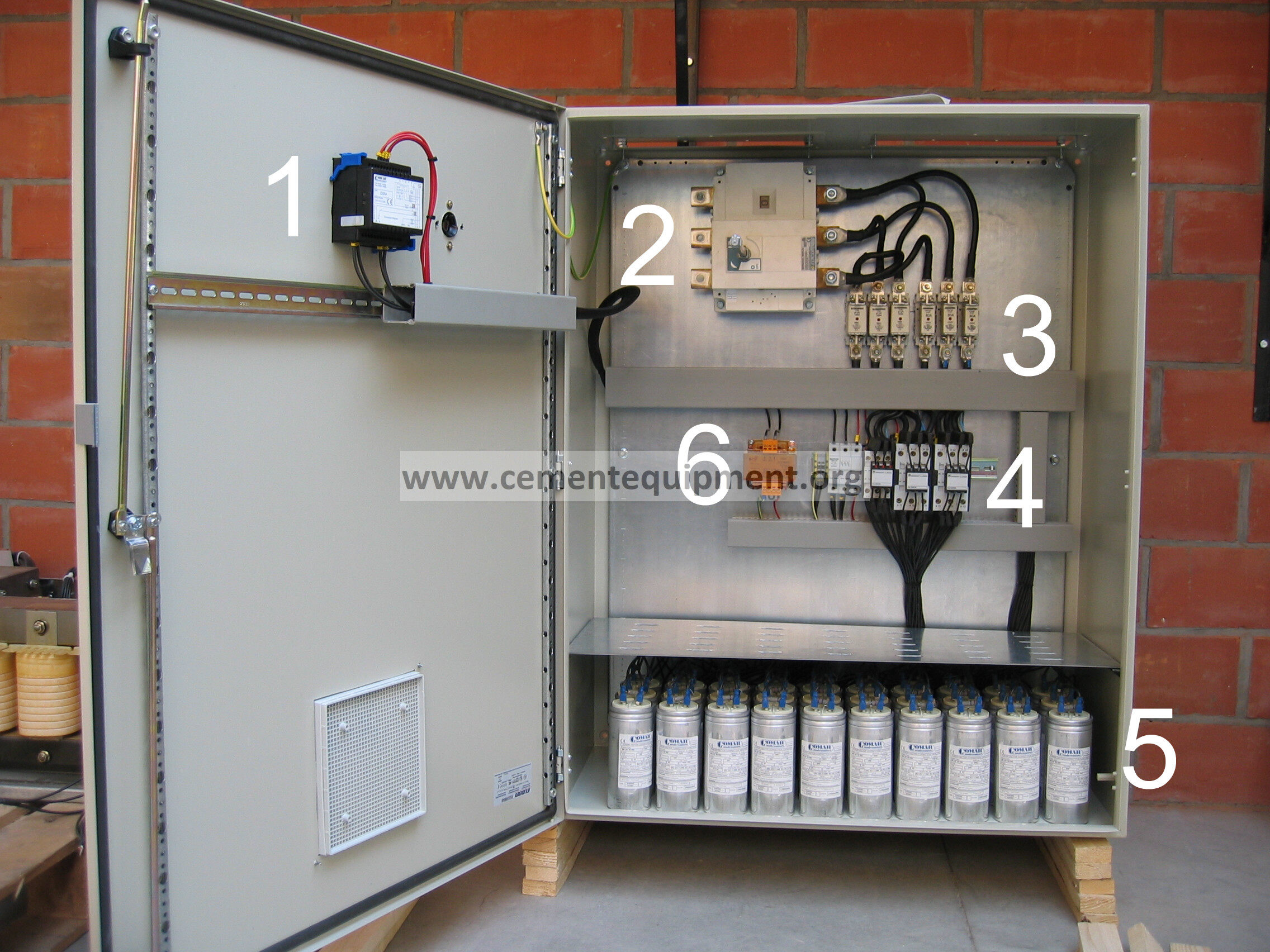
A contactor may close while a fuse, capacitor unit or connection is failed. Compare step current and kvar contribution. A weak/dead step can make the regulator repeatedly call for more correction.
5. Inspect contactors and switching devices
Worn capacitor-duty contactors or thyristor modules can fail intermittently. Review switching counts, heating and electrical condition under approved maintenance procedures.
6. Check harmonic conditions
High harmonic voltage/current can change capacitor current and create resonance or protection events. If detuned reactors are fitted, verify their condition and investigate power quality before increasing capacitance.
7. Prove stable correction over the load cycle
After correcting CT, settings or failed steps, trend several production cycles. Confirm power factor remains in the approved range without excessive step switching.
Evidence-to-decision table
| Evidence | Likely direction | Next check |
|---|---|---|
| One step cycles repeatedly | Step contribution or threshold issue | Step current, fuse, capacitor and contactor |
| All steps hunt near target PF | Deadband/delay or CT issue | Controller settings and CT wiring |
| Command ON but no kvar/current increase | Failed step | Fuse, contactor, capacitor unit |
| Hunting follows large motor cycling | Real reactive-load variation | Load profile and switching delay |
| Capacitor current abnormally high/distorted | Harmonic/resonance concern | Power-quality assessment |
Use step contribution to separate a controller problem from a weak capacitor step
Trend controller demand, commanded step number and the actual phase current or kvar contribution immediately after each switching event. A healthy step should make a repeatable contribution under comparable voltage and load. If the controller commands a step ON but the measured reactive contribution is absent or much lower than the bank baseline, investigate that step’s fuses, contactor or thyristor switch, capacitor unit, connections and detuning reactor where fitted before changing the regulator target.
If every step contributes normally but the bank still toggles around the setpoint, the problem is more likely in load volatility, CT/reference configuration, deadband, switching sequence or switching delay. This distinction is important because widening a deadband can reduce visible hunting while leaving a failed capacitor step undiscovered.
Field verification sequence after the repair
- Confirm CT ratio, polarity, phase reference and regulator wiring against the approved drawing.
- Record power factor and kvar demand with the bank temporarily stable before the next automatic decision.
- Observe each commanded step and verify that actual capacitor current/reactive contribution appears.
- Trend the regulator through a normal cement-plant load cycle that includes large motors or mills starting and stopping where relevant.
- Check that steps do not reverse repeatedly around one threshold and that no one step shows abnormal current, heating or protection activity.
- If harmonic distortion is significant or detuned reactors are installed, review the plant power-quality assessment and reactor/capacitor condition before increasing compensation.
If hunting returns after a short stable period, look for the repeating trigger instead of repeatedly changing the target power factor. Common repeat mechanisms include one intermittent contactor, a failing fuse, CT wiring disturbed during maintenance, a large cyclic load crossing the decision threshold, or a regulator that sees distorted current under changing harmonic conditions.
Return-to-service acceptance criteria
Accept the bank when actual capacitor-step current matches expected contribution, controller feedback is correct, power factor remains within the plant target and switching frequency is reasonable through representative production.
Common mistakes
Do not tighten the power-factor target until hunting disappears. Do not assume a contactor command means a healthy capacitor step. Do not change CT wiring or work inside the bank energized. Do not ignore harmonics. Finally, use the regulator, capacitor and plant electrical design criteria rather than generic PF settings.
Build a stronger cement maintenance library
The Infinity for Cement Organization technical package contains 900+ technical files for cement professionals. It is a one-time $249.99 purchase, with instant download immediately after payment and lifetime updates forever at no additional cost.