Quick answer
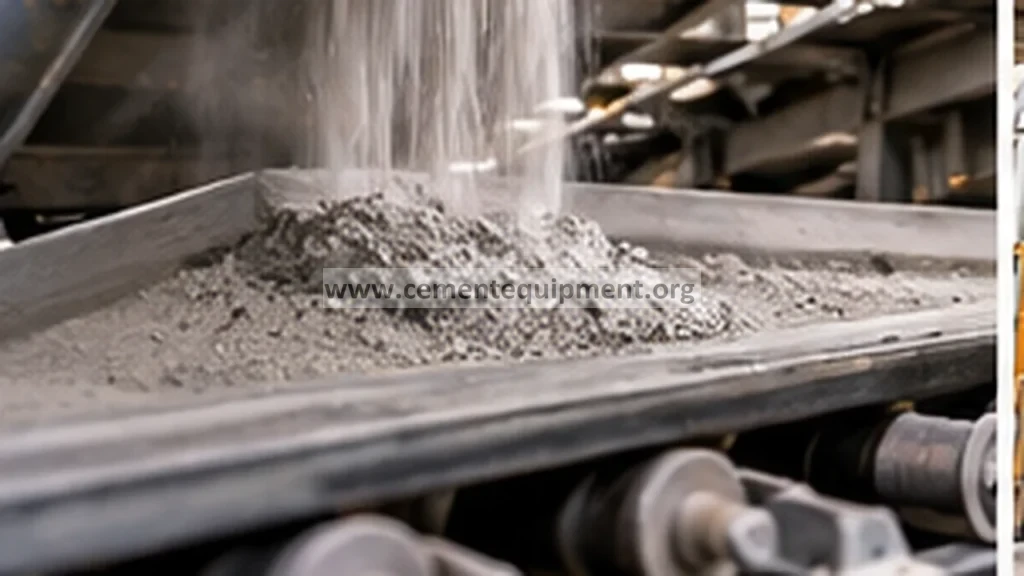
Pressure oscillation in a cement pneumatic-conveying line can be caused by worn elbows, but the elbow is only one part of the system. Diagnose the problem by correlating pressure pulses with feed rate, blower load, material condition, elbow wall-thickness loss, impact-zone wear, downstream restriction and air leakage. A worn elbow can change flow geometry, create local turbulence, leak air or progress toward perforation, all of which can destabilize conveying.
Problem / job
Repeated conveying-pressure spikes, unstable transfer rate, increased blower demand or dust leakage around bends.
Evidence
Trend line pressure, blower current, conveying-air flow, material feed rate, elbow wall thickness and the exact location of wear marks.
Decision
Separate elbow wear from overfeeding, poor air-to-solids ratio, downstream blockage, rotary-valve leakage and changing product condition.
As-found evidence before opening the line
Capture the operating condition while the fault is present. Record conveying pressure at the source and, if available, at downstream points; blower current or power; conveying-air flow; solids feed rate; transfer duration; material temperature; fineness; moisture; and receiver/filter differential pressure. Note whether oscillation appears only at high feed, after product change, after a route change or continuously.
Inspect accessible elbows for external thinning, patch repairs, dust traces, vibration and hot or polished areas. Do not assume the most visibly worn elbow is the cause. A line can contain several bends with different wear rates, and a downstream restriction can create pressure pulses upstream even when the elbows remain intact.
Seven-step diagnostic workflow
1. Correlate pressure spikes with material feed
Trend pressure and feed rate on the same time base. If pressure pulses begin immediately when solids feed rises, check whether the air-to-solids relationship has changed. If oscillation continues after feed stops, investigate blower control, valve leakage, line blockage or receiver-side effects.
2. Compare blower demand with a known-good condition
Higher blower current or reduced available airflow at the same conveying duty can point toward increased system resistance. Confirm inlet filter condition, blower performance and control-valve position before attributing the entire change to the conveying pipeline.
3. Inspect elbow wear pattern
After safe isolation and depressurization, inspect bends at the expected impact zone. Measure wall thickness using the plant’s approved method and compare multiple points around the elbow. Localized thinning on the outer radius is common in abrasive service, while unusual side wear can indicate swirl, poor upstream geometry or maldistribution.
4. Check for leakage before full perforation
Small leaks can admit or release air and alter local conveying conditions. Look for dust staining, temporary patching, gasket damage and worn connections. A leaking flange near an elbow can imitate elbow-wall failure and should be corrected before conclusions are drawn.
5. Rule out downstream restriction
Inspect the route beyond the suspect elbow: next bend, diverter, flexible connection, receiving vessel, filter and discharge device. A partially blocked line or restricted receiver can create cyclical pressure buildup and release. If possible, compare pressure behavior on an alternate conveying route.
6. Review conveying velocity and product condition
Changes in material fineness, moisture, temperature or density can alter saltation tendency and bend wear. Too little air can promote unstable plugs; excessive velocity can accelerate erosion. Use the system designer or OEM limits rather than applying a generic velocity target.
7. Verify the correction with repeatable data
After replacing the damaged elbow or correcting the true cause, repeat the same operating test. Confirm that pressure becomes stable, blower demand returns toward baseline, throughput is recovered and no new dust leakage appears. Record the new elbow condition as the starting point for future thickness trending.
Evidence-to-decision table
| Observed evidence | Most likely direction | Next check |
|---|---|---|
| Outer-radius wall thinning plus dust trace | Elbow erosion/leakage | Thickness map and replacement decision |
| Pressure spikes only at high solids feed | Air-to-solids imbalance or restriction | Feed-rate and airflow correlation |
| High pressure with high receiver-filter DP | Downstream restriction | Receiver filter and discharge path |
| Normal elbow thickness but unstable pressure | Another system cause | Rotary valve, diverter, blower and line condition |
| Wear concentrated abnormally on one side | Flow maldistribution or upstream geometry effect | Inspect preceding pipe and fittings |
Return-to-service acceptance criteria
Return the system to normal operation only when the repaired line is leak free, wall thickness is acceptable to the plant or OEM standard, conveying pressure is stable at representative load, blower demand is reasonable and transfer time matches the expected operating range. Add the replaced elbow to a thickness-monitoring route so wear is identified before another instability or perforation event.
Common mistakes
Do not replace an elbow solely because it looks polished. Do not ignore receiver pressure and filter differential pressure. Do not increase conveying air automatically to suppress pressure pulses; excessive velocity can accelerate wear. Do not rely on one thickness measurement. Finally, do not leave temporary patches as a permanent wear-management strategy without engineering approval.
Related Infinity guides
Build a stronger cement maintenance library
The Infinity for Cement Organization technical package contains 900+ technical files for cement professionals. It is a one-time $249.99 purchase, with instant download immediately after payment and lifetime updates forever at no additional cost.