Quick answer
A bag filter that cleans poorly even though compressor pressure looks normal may be losing pressure between the receiver and the pulse valves. Diagnose the system dynamically: trend header pressure during a cleaning sequence, compare pulse recovery time, inspect isolation and regulator restrictions, check drains and leaks, and verify diaphragm-valve response before changing pulse timing or increasing pressure.
Problem / job
High differential pressure, weak bag cleaning or repeated pulse demand appears while the compressed-air system seems available.
Evidence
Capture receiver and local-header pressure, pressure sag per pulse, recovery behavior, pulse sequence, valve sound, condensate condition and differential-pressure trend.
Decision
Separate air-supply restriction, undersized or depleted storage, leakage, diaphragm-valve faults and control-sequence problems from genuine dust-loading or bag problems.
Capture the as-found condition before adjustment
Do not begin by raising the regulator setting or shortening the cleaning interval. Record the filter differential pressure, process gas flow or fan condition, compressor/receiver pressure, local cleaning-header pressure, pulse-controller mode, active cleaning sequence and whether the problem is continuous or appears only during rapid pulsing. Note which rows or compartments are affected. Listen for continuous air leakage and inspect drains for water or oil carryover. This baseline prevents a control change from hiding a mechanical restriction.
The useful comparison is dynamic rather than static. A gauge can show acceptable pressure between pulses while the header collapses when several valves fire. Compare pressure immediately before a pulse, the minimum reached during the pulse event and the recovery before the next commanded pulse. Use the plant or filter OEM limits for acceptance; do not invent a universal pressure threshold because valve size, header volume, pulse duration and bag-filter design differ.
Seven-step troubleshooting workflow
1. Confirm the symptom belongs to the cleaning system
Trend differential pressure against production rate, gas flow and cleaning activity. If differential pressure rises while gas flow and dust load are stable and cleaning commands increase without effect, weak pulse energy becomes credible. If the pressure rise follows a process-load increase, moisture event or dust-property change, investigate those causes in parallel.
2. Compare receiver pressure with local header pressure
Measure as close as practical to the receiver outlet and at the filter cleaning header. A large difference under pulse demand points toward a restriction between those locations: partially closed isolation valve, regulator limitation, clogged filter, undersized line, damaged hose or obstructed fitting.
3. Observe pressure sag and recovery
Watch several complete cleaning cycles. A progressive pressure decline across successive pulses suggests the supply cannot replenish the header at the commanded rate. A sharp isolated drop associated with one valve may instead indicate an abnormal valve event or excessive pulse duration. Record the sequence rather than relying on a single gauge reading.
4. Check for leakage and unintended air consumption
With the system in a safe state, inspect manifolds, fittings, drain valves, solenoids and diaphragm valves for leakage. A valve that does not fully reseat can consume stored air continuously and reduce the energy available to subsequent rows. Use safe plant-approved leak-detection methods and isolate energy before intrusive work.
5. Inspect regulator, filter and condensate management
Restrictions can develop gradually as filter elements load or regulators become unstable. Condensate can also interfere with pneumatic components and accelerate valve problems. Compare upstream and downstream behavior under demand and service components according to the filter and pneumatic-system manufacturer instructions.
6. Verify diaphragm and solenoid valve response
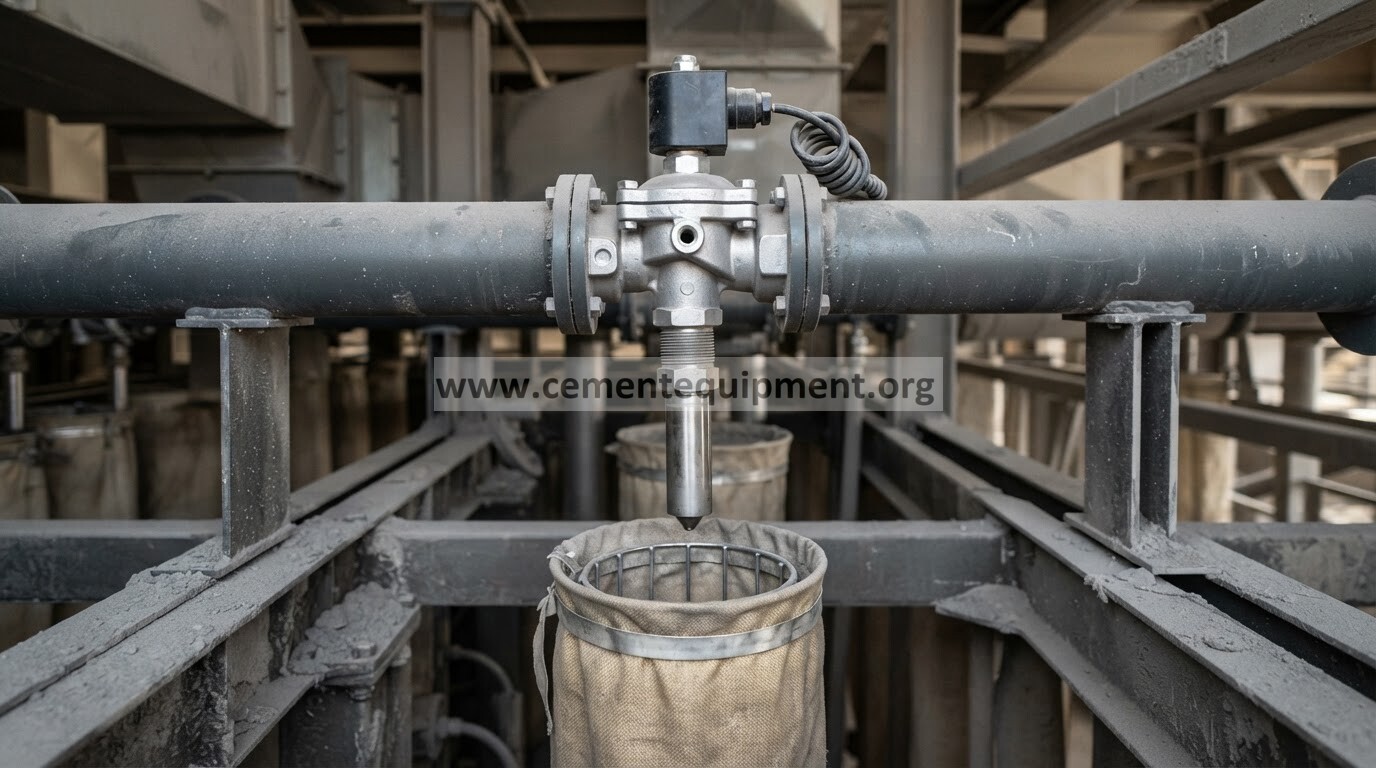
Confirm that each electrical command produces a clean pneumatic pulse. Compare sound, timing and pressure response across rows. A delayed, weak or prolonged event can indicate pilot blockage, solenoid problems, diaphragm damage, contamination or an exhaust restriction. Do not assume every weak pulse is caused by low compressor pressure.
7. Review pulse sequence only after mechanical checks
Confirm pulse duration and interval against the OEM configuration and the actual process duty. Excessively frequent pulsing can prevent header recovery; unnecessarily long pulses can waste air without improving cleaning. Restore the intended sequence after correcting supply or valve faults, then verify filter differential-pressure response over a representative operating period.
Diagnostic decision table
| Evidence | Most likely direction | Next check |
|---|---|---|
| Receiver stable, local header falls heavily during pulses | Distribution restriction or insufficient local storage/replenishment | Isolation valves, regulator, filter, line and header path |
| Both receiver and header decay during rapid cleaning | Supply capacity or excessive aggregate demand | Compressor/receiver availability and concurrent air users |
| One pulse causes abnormal sag or long discharge | Valve or pulse-duration problem | Solenoid, pilot, diaphragm and controller output |
| Header pressure healthy but one row cleans poorly | Local valve/blowpipe/nozzle or bag-row issue | Valve response, blowpipe alignment and row condition |
| Cleaning system responds normally but DP remains high | Dust/process/bag restriction rather than air-header fault | Gas flow, moisture, dust loading, bags and hopper evacuation |
Verification and return-to-service criteria
Return the system to normal service only after the commanded pulse sequence is repeatable, the local header recovers consistently between pulses, no continuous pneumatic leakage is evident, drains and air-treatment components operate correctly, and each valve produces a consistent response. Confirm that differential pressure stabilizes or responds in the expected direction at comparable process load. Document the as-found and after-repair trends so future deterioration can be identified earlier.
Acceptance values should come from the installed bag-filter, pulse-valve and pneumatic-system documentation. Where the plant has alarm limits or baseline trends, use those controlled references rather than generic internet numbers.
Common mistakes and repeat-failure traps
- Increasing regulator pressure before proving where pressure is being lost.
- Judging the system from a static gauge reading between pulses.
- Shortening pulse intervals until the header has no recovery time.
- Ignoring a leaking diaphragm valve because the compressor can temporarily keep up.
- Changing several controller settings at once and losing the diagnostic baseline.
- Treating every high-DP event as a cleaning-air problem while ignoring moisture, gas flow, hopper evacuation or damaged bags.
Related Infinity guides
Reference discipline
Use the installed filter OEM manual, pulse-valve manufacturer instructions, pneumatic schematic, compressor/receiver documentation and plant baseline trends for equipment-specific limits. This guide provides a fault-isolation sequence, not a substitute for site lockout procedures or manufacturer settings.
Continue with the Infinity technical library
The Infinity for Cement Organization technical package includes 900+ technical files for cement-plant engineering and maintenance. It is a one-time $249.99 purchase with instant download immediately after payment and lifetime updates forever at no additional cost.