Most Complete & Professional Burner Calculation , last sheet you will download| perfect
CLICK HERE NOW TO DOWNLOAD MOST IMPORTANT BOOKS IN CEMENT INDUSTRY + PRACTICAL EXCEL SHEETS TO HELP YOU IN YOUR DAILY WORK
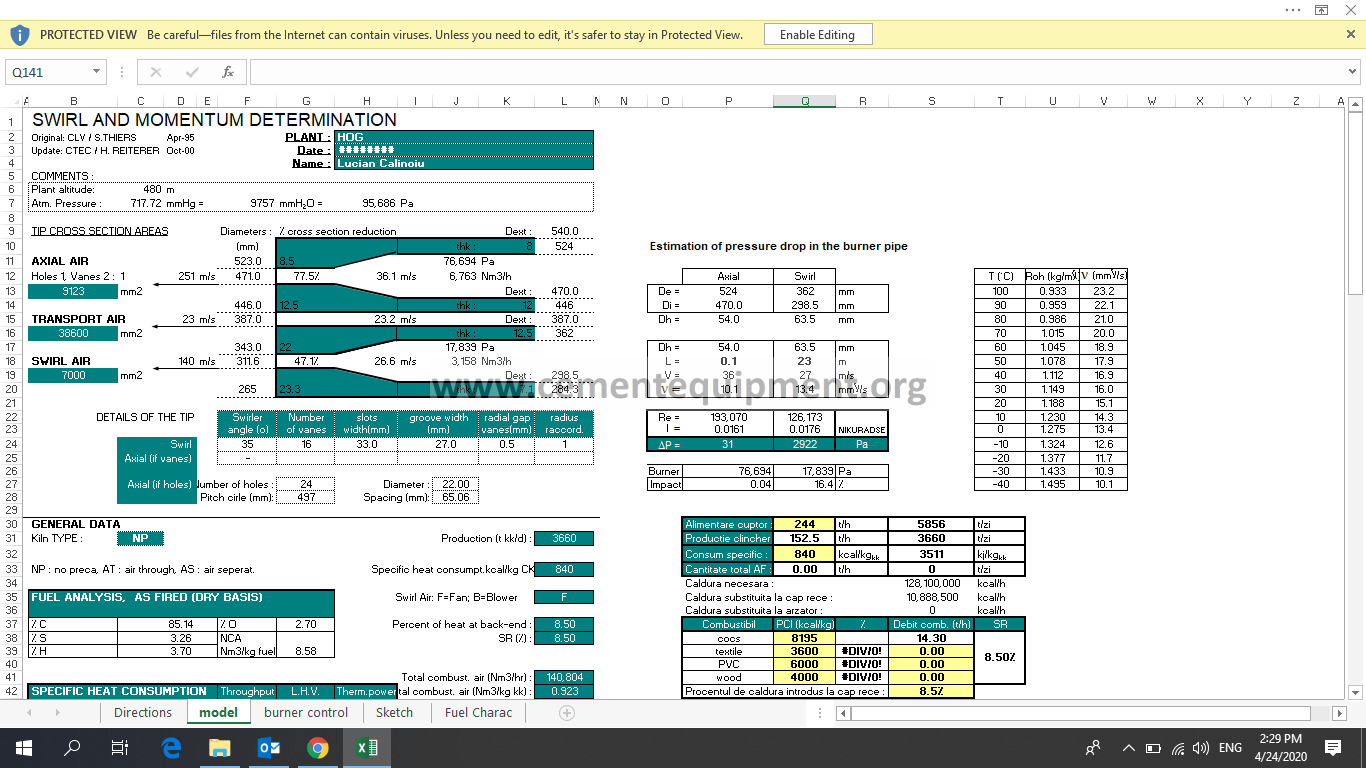
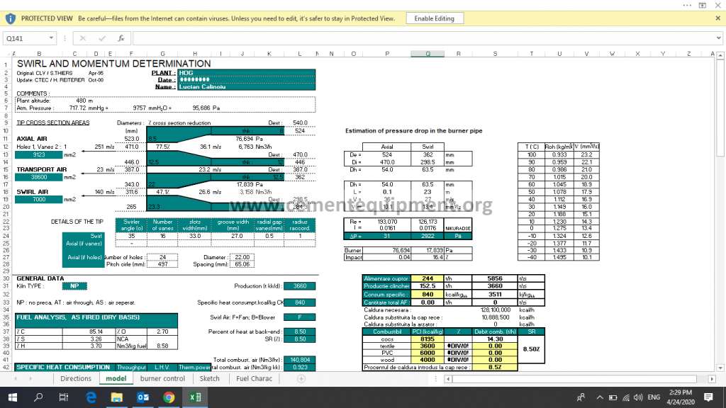
| 1) Input Fuel characteristics | |||||||
| 2) Input kiln production data | |||||||
| 3) Determine (goal seek) transport air flow rate : 5 kg/m3 for blower, 7 kg/m3 for pump | |||||||
| – vary the transport flowrate – Nm3/h | |||||||
| – note that blowers cannot take the higher material density rate | |||||||
| 4) Obtain optimum or target flow rates values (swirl & axial) | |||||||
| For a first calculation, start with static pressures of 40.000 Pa for axial, and | |||||||
| 25.000 Pa for swirl – 10% primary air; 7% axial + transport (in case that no swirl | |||||||
| is used). Use solver, changing the groove width, the axial holes diameters, the axial and | |||||||
| the swirl static pressures. Add constraints on the axial pressure (35.000-60.000 Pa), | |||||||
| and to the swirl pressure (>18.000 Pa if fan, 20.000-30.000 Pa if blower). | |||||||
| Note the optimum flow rates as well as cross section areas (mm2) | |||||||
| Ultimate target is Is = 1.8 and Sw = 0.15. | |||||||
| 5) Dimension the barrel: | |||||||
| What is the free diameter required in the centre? Depends on how many fuels | |||||||
| the plant wants to burn simultaneously: waste, oil, etc… | |||||||
| In theory, min. of 200 mm (8 in.) is needed for the bluff body effect although | |||||||
| 6 in. has been used. | |||||||
| Use standard pipes (see table). The outer diameter of this first pipe is the inside | |||||||
| diameter for the swirl air channel. Continue to build, using the criteria below: | |||||||
| 1) Swirl: | Velocity in barrel: 15 to 25 m/s | ||||||
| Swirler angle = 30 – 40°; common to use 35° | |||||||
| 18 to 22 vanes (or slots), 8 mm depth minimum | |||||||
| No straight stream through the swirler = long enough | |||||||
| 2) Transport: Velocity in tip and barrel: 25 to 35 m/s | |||||||
| radial gap of annulus > or = to 10 mm (concentricity, plugging) | |||||||
| A slight reduction of the cross section area is being done at the tip, for | |||||||
| a better fuel distribution around the annulus (automatic) | |||||||
| 3) Axial: Velocity in barrel = 15 to 25 m/s (trade-off weight of burner pipe versus | |||||||
| pressure drop). Target 20 holes, generally 16 to 24 | |||||||
| Diameter of holes >or = to 12 mm |
|
||||||
| 6) Once the barrel is complete, adjust the tip cross sectional areas | ||||||
| Ultimate target is Is = 1.8 and Sw = 0.15, by adjusting the tip dimensions. | ||||||
| Change the tip cross sectional areas by adjusting the axial holes | ||||||
| diameter and the width of groove for the swirl. | ||||||
| 7) Optimise static pressures at tip, tip cross sectional area and all other | ||||||
| constraints. Obtain the best balance for: | ||||||
| Target of Is = 1.8 and Sw = 0.15,. | ||||||
| Optimum flow rates | ||||||
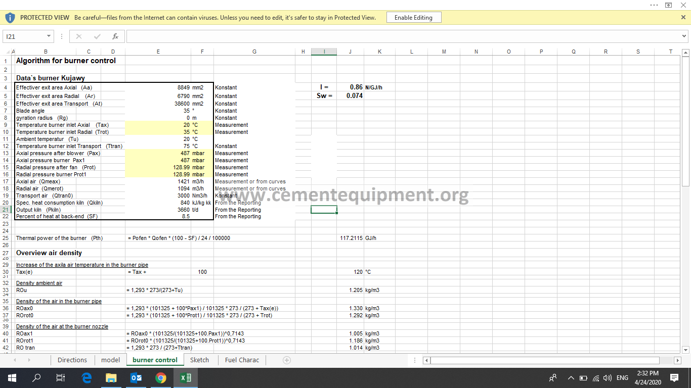
| 8) Confirm choice of fan or blower for swirl air based on static | ||||||
| pressure in the tip – choice effects bias coefficient | ||||||
| 9) Determine range for blowers: maximum for (Is,Sw)=(1.8,0.15), and | ||||||
| minimum for (0.9,0.05). Check that , doing this, we stay in the range | ||||||
| of 7 to 12% primary air. |
|
|||||
| Transport design: drawing instructions | |||||
| Maximum angle of inlet = 12.5 degree with the burner axis | |||||
| Enter from the top (better distribution) | |||||
| Inlet rectangle: Internal width should be equal to internal | |||||
| diameter of outer pipe of the fuel annulus. The velocity | |||||
| should never decrease from the fuel intoduction into the line | |||||
| to the burner tip. (Settlement) |
|
||||
To Download the Excel sheet and most important cement books and documents click here now
to Download this sheet only click here