Contents
THE MOST COMPREHENSIVE ARTICLE ABOUT ROTARY KILN ON THE WORLD WIDE WEB INTERNET
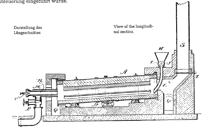
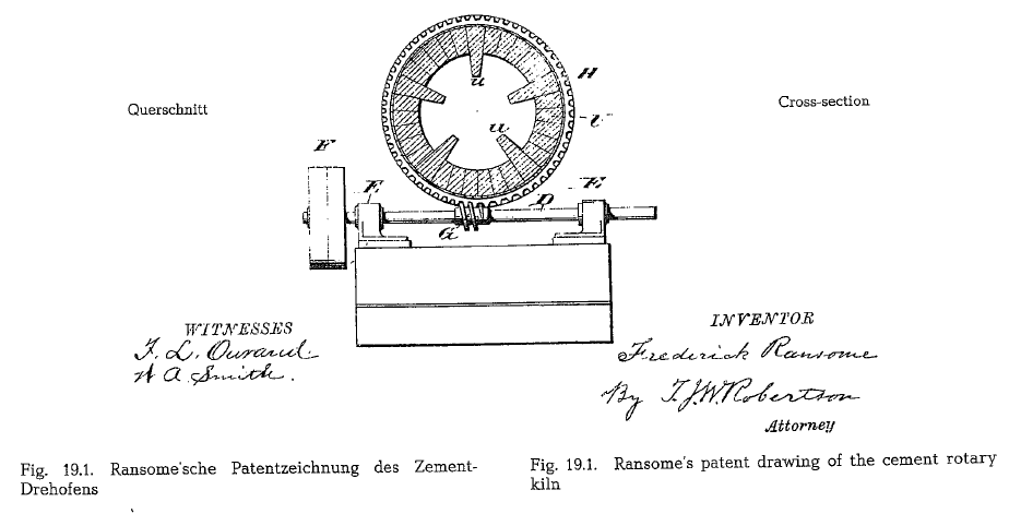
It was Frederik Ransome who introduced the rotary kiln into the cement industry. For his invention, Ran some first took a patent in England (English Patent No 5442 of May 2, 1885, entiled: Improvement in Manufacturing Cements, etc.), and then in the United States (U.S. Patent No 340,357 of April 20, 1886 under the heading: Manufacturing Cements, etc.). Fig. 19.1. shows a reproduction of Ransome’s patent drawing of a cement rotary kiln. This rotary kiln was gas fired, since coal dust firing was not known at that time. Later fuel oil firing was applied before coal dust firing was finally brought into use.
TO DOWNLOAD THE EXCEL SHEET AND ALL THE OTHER USEFUL BOOKS AND RESOURCES KINDLY CLICK HERE
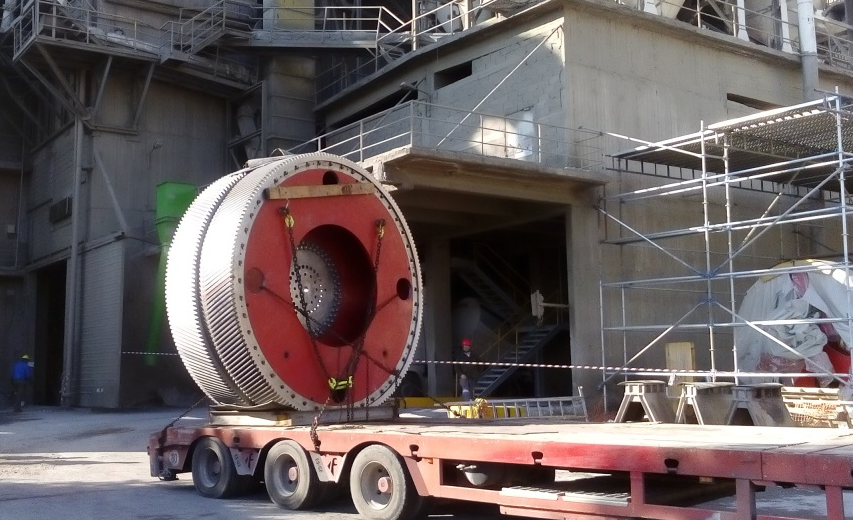
The dimensions of the first cement rotary kilns were approximately: 1.8-2.0 m in diameter, at a length of approximately 20- 25 m, with throughput capacities of about 30- 50 t/24 h.
As the cross-section view shows, Ransome applied already so-called lifter-bricks for better heat transfer from the kiln gas to the kiln feed. It was many decades later when lifter bricks were once more applied in the rotary kiln.
Types of rotary kilns
The following shows the prevailing types of rotary kiln cylinders (see Fig. 19.2.):
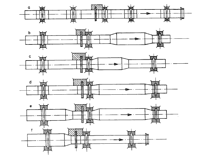
Fig. 19.2. a. Straight rotary kiln; b. Rotary kiln with enlarged burning zone; c. Rotary kiln with enlarged calcin ing zone; d. Rotary kiln with enlarged calcining and burning zone; e. Rotary kiln with enlarged drying, calcining and burning zone (wet process kiln); f. Rotary kiln with enlarged drying or preheating zone (long dry process or wet process kiln)
The aim of the zone enlargement is the extension of the material”s residence time in the particular kiln zone; simultaneously it is the intention to decrease the gas velocity for better heat transfer from the kiln gas to the material. However, this causes different transportation times resulting in irregular material passage, thus impairing the kiln’s operation. In the transition zones from the large to the smaller cross sections material stowage takes place, causing abra sion and dust. The manufacture of transition pieces is more expensive than that of straight kiln sections. The lining of tapered sections is a complicated and highly labor consuming job, requmng specially shaped refractory bricks. A kiln shell shaping which is particularly disadvantageous, is the narrowing of the kiln’s discharge end; this results in partial cooling of the clinker in the kiln and in a rapid wear of the refractory in this section.
Practical experience as well as theoretical delibera tions lead to the observation that rotary kilns without constrictions or enlargements represent currently the most useful kiln construction. The shells of modern preheater kilns already show uniformity throughout the cross-sections. Unfavorable experience with rotary kilns of different cross-sections, prompted the cement industry of the Soviet Union to build rotary kilns with an invariable diameter exclusively.
Degree of kiln filling
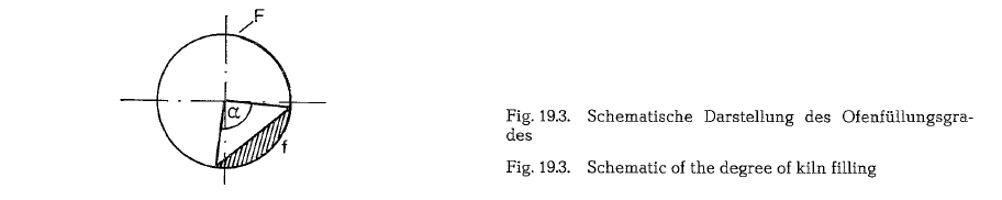
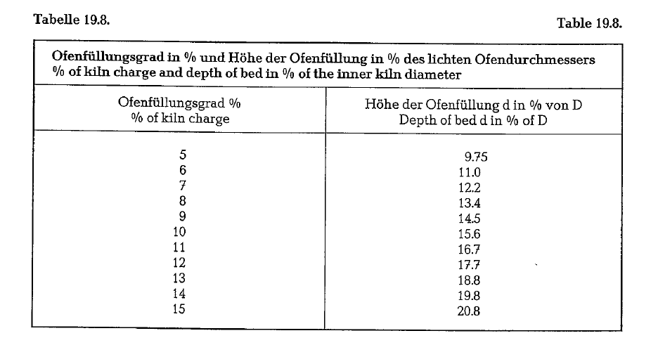
The feed forms a segment of the rotary kiln’s cross section. The area ratio of this segment to the area of the kiln’s cross-section expressed in percent is called the kiln’s degree or percent of filling f, (see Fig. 19.3.).
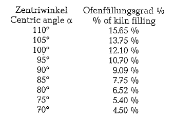
Kiln filling degrees fluctuate within the limits of about 5-17 %. Independent from. the kiln’s diameter, the percent of filling for the different values of the centric angle a. is as follows:
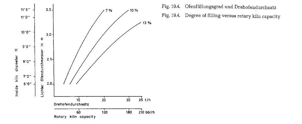
The influence of the degree of filling to the rotary kiln’s capacity is shown in Fig. 19.4. Three curves represent filling degrees of 7, 10, and 13 %, with the corresponding capacities in t/h for rotary kilns with diameter from. 2 to 3.5 m..
Kiln slope
No generally valid rule exists for the proper slope of rotary kilns. Rotary kilns show slopes from. 2 to 6 0/o.
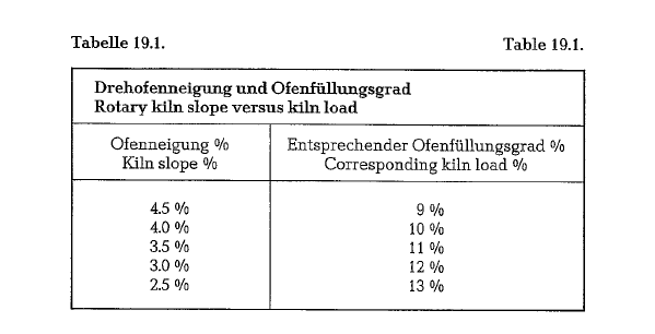
Most kiln slopes are between 2 and 4% to the hori zontal. Originally, rotary kilns had higher slopes with lower revolutions ranging from 0.5 to 0.75 rpm. Lower kiln slopes require higher numbers of revolutions; this has the benefit of better mixing of the kiln feed, together with a more intensive heat exchange. Lower slopes also permit higher degrees of kiln filling or of kiln load. Practical experience resulting from kiln operation shows that the following kiln slopes yield the corresponding average kiln loads; see table 19.1.
On the other hand, it is said that the kiln load depends on the length (L) to diameter (D) ratio of the kiln. Wet process rotary kilns with an LID-ratio of 40 and more, show kiln loads of up to 17 % [176]. In any case it is the rotary kiln’s slope which determines the kiln’s load in the first place; in addition to this is an increasing LID-ratio a factor, which can contribute to the kiln’s higher load.
In practical kiln operation the kiln load should not exceed 13 %, since higher kiln loads impair the heat transfer.
The following rotary kiln slopes were found by Boh man [177] to be correct:
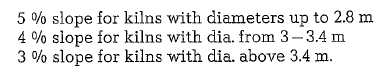
As until now, this recommendation proved good, since most of the rotary kilns with diameters above 3.4 m show slopes of about 3-3.5 %.
Long American dry and wet process kilns show, in most cases, slopes of 7/16 to 1lz inch per foot length, which equals a slope of about 3.5 %. This is the reason why American rotary kilns are operated with higher revolutions (from about 80 to 110 rph).
The USSR tried to go a step further by experimen tally operating a 3 x 35 m suspension preheater kiln with 19-20 rpm. At this number of revolutions, the kiln feed turned into a fluidized-like state. At 20 rpm the kiln feed had a traveling speed of 260 m/h. The residence time in the burning zone was 3 minutes; this period of time, it is reported, sufficed for clinker formation, since the raw mix contained mineralizers. The kiln throughput was 632 t/24 h, which equals a specific kiln capacity of 3.1 t/24 h · m3 of useful kiln volume [178].
Slope designations of rotary kilns
Four different systems of measurement are in use to designate the slope of rotary kilns:
- Conventional angular degrees
- Centesimal degrees, also called gon, e. angular grades, with a centesimal graduation of the quad rant or right angle (R). 1 centesimal degree or gon
= 0.9° = 54′ = 3240″ of conventional angular degrees. 1 conventional angular degree = 1.111centesimal degrees.
- Pitch in inches or fractions of an inch per foot length; this slope indication is also called This designation is exclusively used in the Ameri can cement industry to specify the slope of rotary kilns.
- Slope in percent; this slope indication expresses the tangent of an angle in percent, where 45°= 1 = 100% slope.
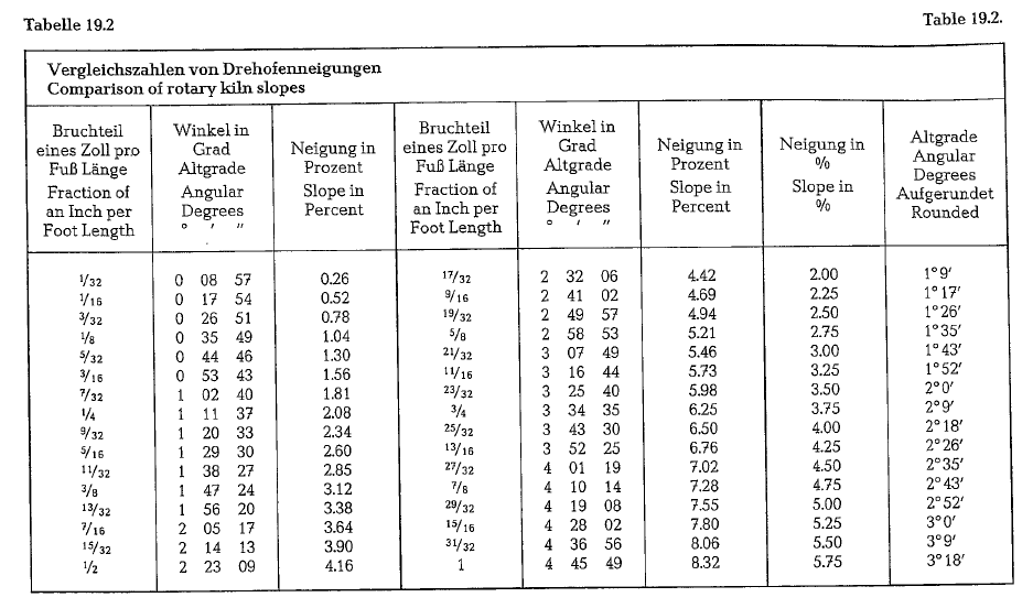
Table 19.2. contains a comparison of slopes of rotary kilns in the three most used systems, i. e. slope in fractions of an inch per foot length; conventional angular degrees; slope designation in percent. This applies also for slopes of drum dryers and rotary clinker coolers.
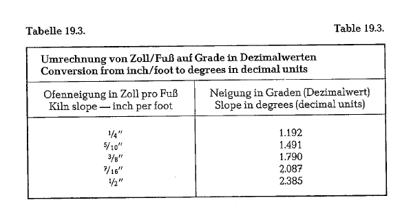
Table 19.3. contains conversion figures for kiln slopes from inch per foot into conventional angular degrees with minutes and seconds in decimals.
Revolutions of rotary kilns
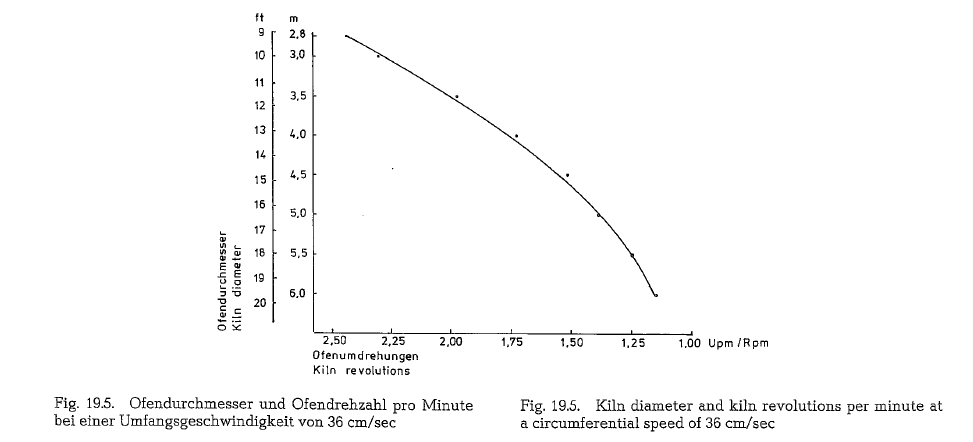
As long as diameters of rotary kilns were in the range of about 2-3m, it was generally referred to the kiln’s number of revolutions. However, since rotary kilns presently show diameters of 6 m and more, the num ber of revolutions is designated by the circumferen tial speed of the kiln shell. To operate rotary kilns economically circumferential speeds of about 35 em/ sec are applied; recently announced circumferential speeds are already in the range of 40- 70 em/sec. Fig.19.5. shows a diagram of kiln revolutions for kilns with diameters from 2.8-6 m, based on a circumfer ential speed of 36 em/sec. KHD Industrieanlagen AG quotes already a speed of 70 em/sec.
Material passage through the rotary kiln
The formula of the U.S. Bureau of Mines for calculation of the passage of particles in rotary kilns [179], was already cited in section 4.15. Material passage through dryers. In the following, this formula is used to calculate the residence time (t) of particles in a rotary kiln, with the following assumptions:
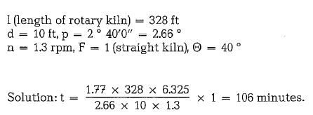
Selecting the proper kiln slope and varying the num ber of kiln revolutions, are possibilities to control the residence time of the kiln feed.
The Bureau of Mines formula is generally used by the American cement industry. There is still a number of other formulas to calculate the residence time of the material in the rotary kiln; these formulas were developed by:
Generally, two processes take place in the rotary kiln:
- The thermochemical process
- The material Passage
The thermochemical process causes the material to pass through the rotary kiln at varying speeds. At constant kiln revolutions, the material passes the var ious kiln zones with different velocities. This was detected with tracer-experiments, at which radioac tive material (isotopes of Na24, and of Mn56) was fed into wet process kilns [188]. Fig. 19.6. shows a rotary kiln with indications of the different material veloci ties along the longitudinal axis.
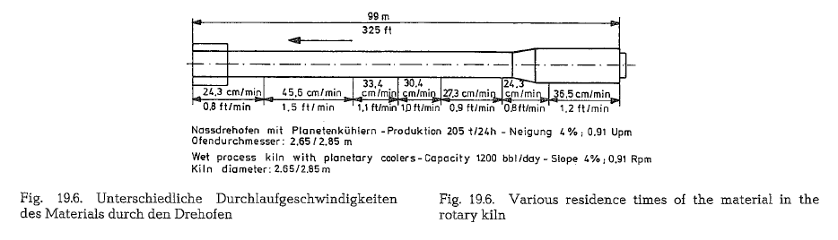
The various residence times result from the mater ial’s physical and chemical changes, which occur during the burning process in the kiln. According to the diagram, the lowest velocity of the material is in the burning zone (24.3 em/min), whereas the highest velocity is in the calcining zone (45.6 em/min). It is the function of the kiln operator, to equalize these variables during the kiln”s run. It is evident that the burning process is combined with a complicated and arithmetically hardly comprehensible material move ment in the rotary kiln.
Rotary kiln power input calculation
The calculation of the kiln drive horsepower is based on two components: [189]
- The friction horsepower
- The load horsepower
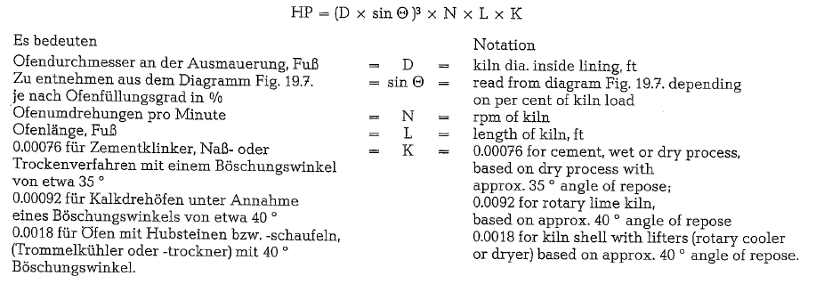
The formula for the friction horsepower is:
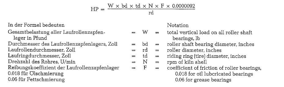
The formula for the load horsepower is:
For multi-diameter kilns, the load-HP should be cal culated separately for each diameter.
Example:
Calculate the drive for a preheater kiln with the fol lowing data: Diameter: 13’6″, length 190ft. Total verti cal load: 1,600,000 lb.
Thickness of kiln lining: 9 in., dia. of roller shaft bear ing: 16 in., dia. of riding ring: 174 in., kiln rpm: 1.7, F =
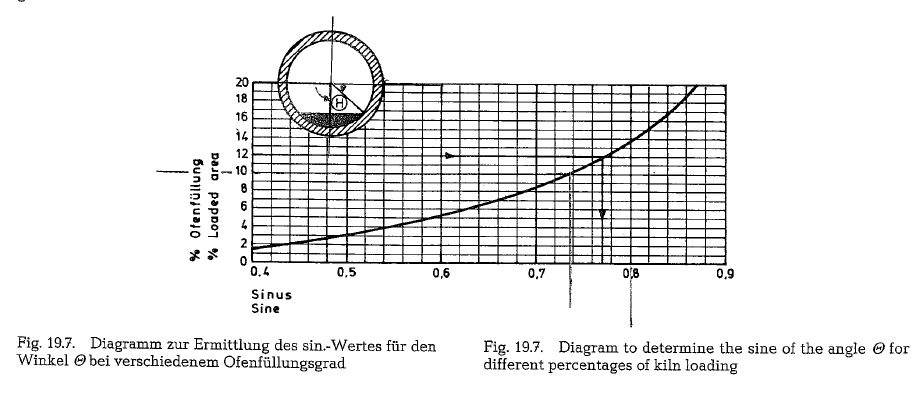
0.018; roller dia. 42 in., kiln loading: 12 %, thus sine e
= 0.77, K = 0.00076.
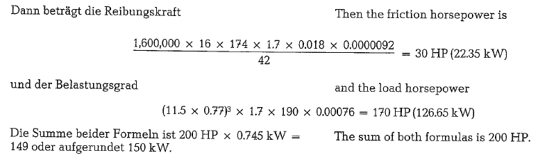
As a matter of fact, rotary kilns of this size are driven by a 200 HP motor.
Vaillant [190] developed similar formulas to calculate the required power input for rotary kilns.
Ratio of rotary kiln volume to the power requirement
If the drive power ascertained in the aforementioned example is brought into correlation to the kiln shell volume, the following ratio results:
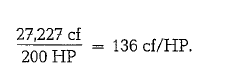
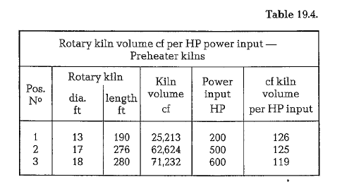
Table 19.4. shows that the specific kiln volume per HP of kiln drive for existing suspension preheater kilns is within the limits of 119 and 126 cf/HP or 4.5-4.8 m3/kW of kiln drive.
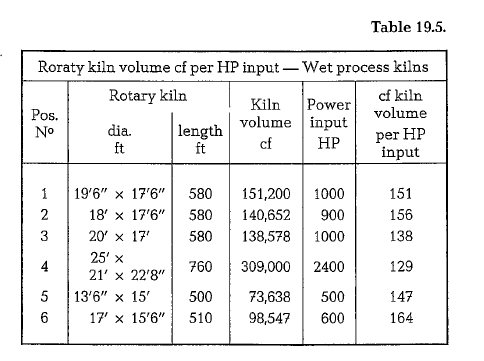
The ratio of kiln volume to the installed kiln power input of wet process kilns is within the limits of 151 and 164 cf/HP; this results from table 19.5.
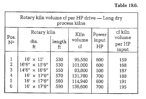
The ratio of kiln volume to the installed kiln drive of long dry process kilns is between 159 and 195 cf/HP; see table 19.6.
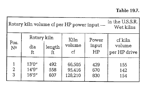
The standardized wet process kilns in the USSR are supplied with the same power input as American wet process kilns; see table 19.7.
The above cited tables show that suspension prehea ter kilns have the highest specific power input of 119-126 cf/HP; then follow wet process kilns with 151-164 cf/HP; and finally long dry process kilns with 159- 195 cf/HP.
The higher specific power input of the preheater kiln cylinders, compared to long rotary kilns, is motivated by the ratio of the length of the burning zone to the total length of the preheater kiln. As is well known, the angle or repose of clinker is larger than that of raw mix; this causes a higher torque of the preheater kiln, resulting in higher power requirement.
The higher power input of wet process kilns, com pared to long dry process kilns is a result of the chain sections; these internal kiln constructions increase the rotating mass of the rotary kiln.
For regular kiln operation, the actual power input is approximately 40- 60 % of the installed power. The additional power input is reserved for possible kiln upset conditions, as disengagement of kiln coating, shooting of kiln rings, etc.
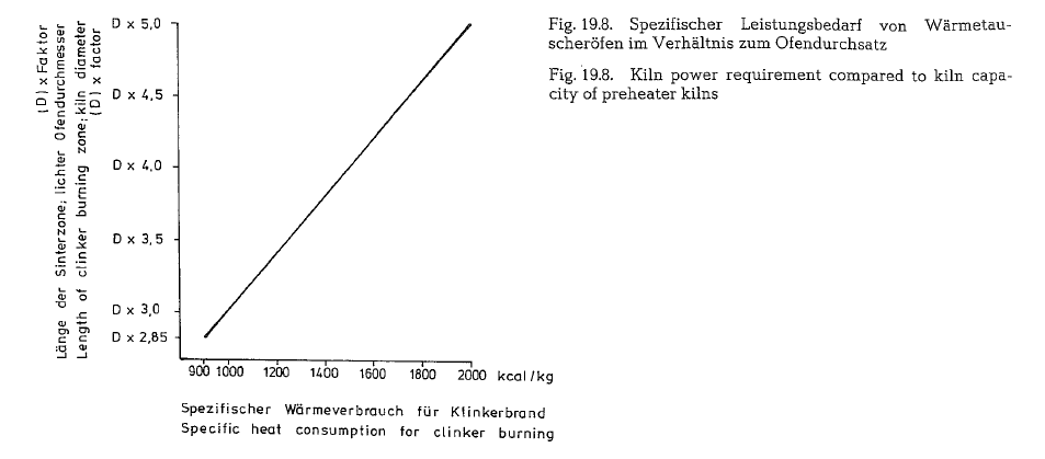
The diagram in Fig. 19.8. shows the total power input of preheater kilns related to the kiln capacity.
Thermal expansion of the rotary kiln
when in operation, length and circumference of the rotary kiln are larger than in the inactive state. This circumstance must be taken into consideration, so that the riding rings can always rest entirely on the rollers and that the seals on both ends of the kiln will not be impaired. To calculate the linear expansion, the cross-section of the kiln with the highest shell temperature is selected as the starting point from which the temperature decreases uniformly towards both ends of the kiln, as is shown in Fig. 19.9. The kiln shown here is 150m long, and the cross-section with the highest shell temperature is located 25m from the lower kiln end.
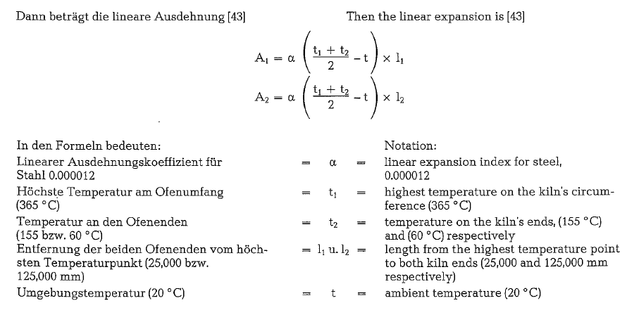
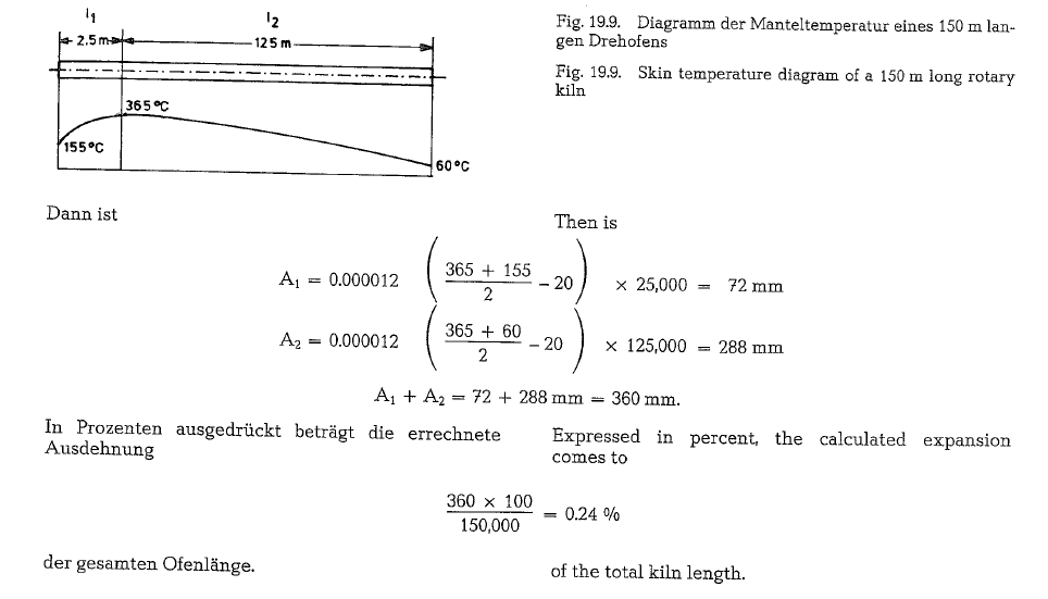
Practically, the kiln expansion is halved, since the kiln is given the possibility to expand from its center,ie. from the thrust rollers towards both ends.
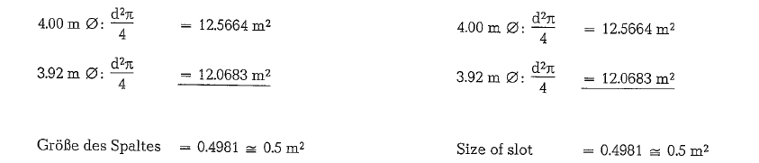
The heating of the kiln shell also causes an expansion along the kiln’s diameter. Where the shell temperature amounts to approximately 300 ac (i.e. where most often the second riding ring is located, if counted from the kiln’s discharge end), the expansion of the 4 m long diameter is:
![]()
![]()
the kiln diameter in the hot state is 4013 mm. When calculating along the kiln’s circumference, we will get the same result:

When lining the kiln with refractories, the expansion must be taken into consideration; this applies also for the arrangement of the riding rings along the kiln shell.
The zones of the rotary kiln
A regular rotary kiln, which is not connected with any kind of preheater, can be divided into the follow-ing processing zones; the length of the processing zones is expressed in percent of the total kiln length:
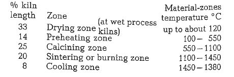
There are no strict boundaries between the kiln zones, since gas-, material- and kiln lining-tempe a tures in the particular zones are hard to ascertam; also, the occuring reactions partially overlap or take a parallel course.
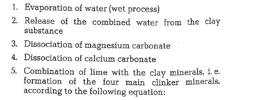
Schematically, the following reactions occur in the rotary kiln:

Rotary kiln air seals
Air seals are used to prevent infiltration of ambient air at both the hot and cold ends of the rotary kiln.
The negative pressure at the hot kiln end is approxi mately 3 mm W. C., and at the cold end (long rotary kilns) approximately 25-30 mm W. C.
The cold kiln end is sealed for the following reasons:
- To prevent an increase in volume of the exit gases by infiltrated Intake of ambient air means more energy consumption for the kiln fan.
- At the relatively low exit gas temperature of wet process rotary kilns, cold infiltrated air can cause the exit gas temperature to fall below the dew point; this means condensation in the flue ducts and dust collectors.
- In rotary kilns with waste heat boilers infiltration of false air causes temperature reduction of the exit gases and thus a lower steam and energy production.
At the hot kiln end infiltrated false air causes disc placement of the hot secondary air emerging fro the clinker cooler. In the rotary kiln the infiltrated arr is heated up to the gas temperature, thus entailing heat losses. The following example shows the amount of heat losses caused by infiltration of false air into the hot end of the kiln.
Example:
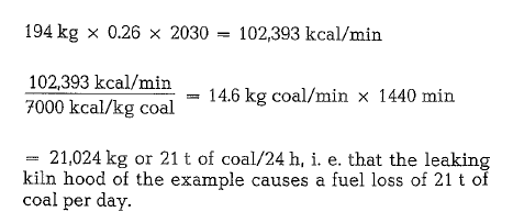
A rotary kiln with a diameter of 4 m is assumed; between kiln shell and kiln hood, there is a 4 em wide open slot, through which false air infiltrates into the kiln.
Further it is assumed that false air is infiltrated with a velocity of 5 m/sec; this equals 0.5 m2 x 5 m/sec =
2.5 m3 of false air/sec, or 2.5 x 60 = 150 x 1.2928 = 194 kg air/min.
The gas temperature in the burning zone of the kiln is 2045 oc. Heating the air from 15 oc to 2045 oc
(2030 deg.), requires the following amount of heat:
A large number of various rotary kiln seals was developed by kiln manufacturers. Only a few of them can be shown here.
Graphite block air seal (a product of the Fuller-Com pany, Bethlehem, Pa. USA). The graphite seal consists of 24 graphite blocks of the size 25 x 150 x 460 mm (depending on the kiln diameter), mounted along the circumference of the kiln. Each graphite block is held in place by an adjustable seal ring, wedge and wedge plate. Each block is held in contact on the kiln shell with two stainless steel springs, to allow the blocks to shift position due to possible radial divergence of the kiln shell. The springs are adjustable to fully utilize the graphite blocks for longer life. Due to the contact between the kiln and the graphite blocks, the en trance of false air is almost completely prevented. The lubricating qualities of the graphite allows the blocks to slide circumferentially and axially, to accomodate the expansion and contraction of the rotary kiln.
Fig. 19.10. shows the graphite block air seal.
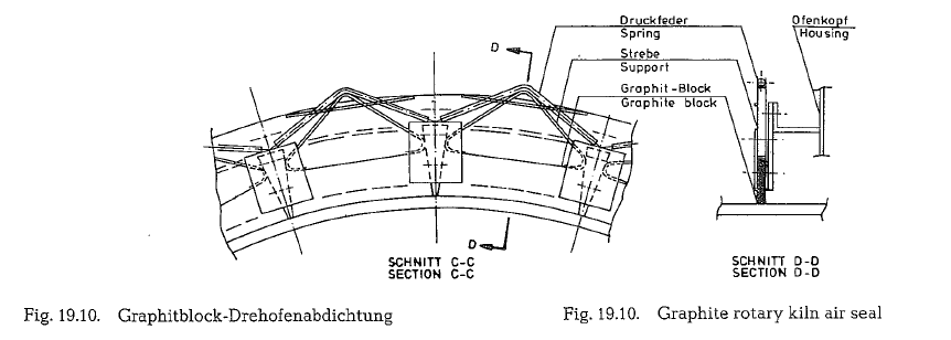
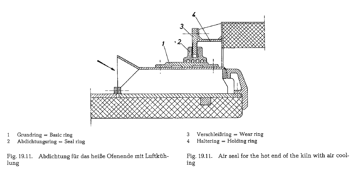
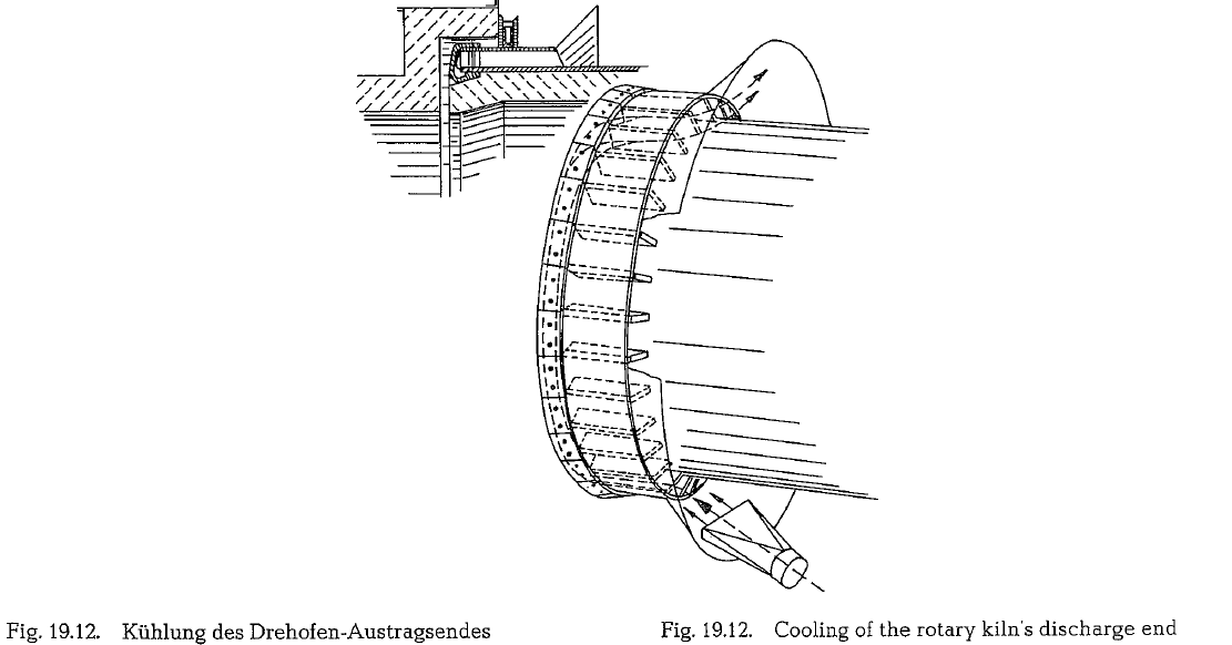
Fig. 19.11. shows a rotary kiln air seal [191] for the kiln’s discharge end, with air cooling of the kiln nose ring which is exposed to the brunt of high tempera tures. The seal is fastened to a cooling ring which is attached to the kiln shell. Cooling air is blown into the space between the outer ring and the kiln shell. A perspective view of this arrangement is shown in Fig. 19.12.
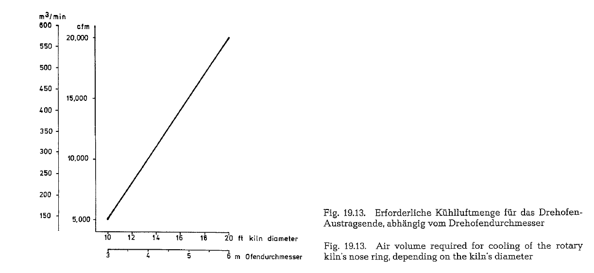
The diagram shown in Fig. 19.13. shows the air vol umes required for cooling of the rotary kiln’s nose ring; the air volume depends on the kiln’s diameter.
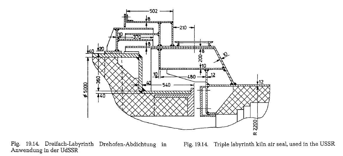
Many different rotary kiln seals are in use in the USSR. of which two interesting models are shown here. Fig. 19.14. shows a triple labyrinth seal, espe cially developed and employed for the hot end of the 5 x 185m Soviet wet process rotary kiln.
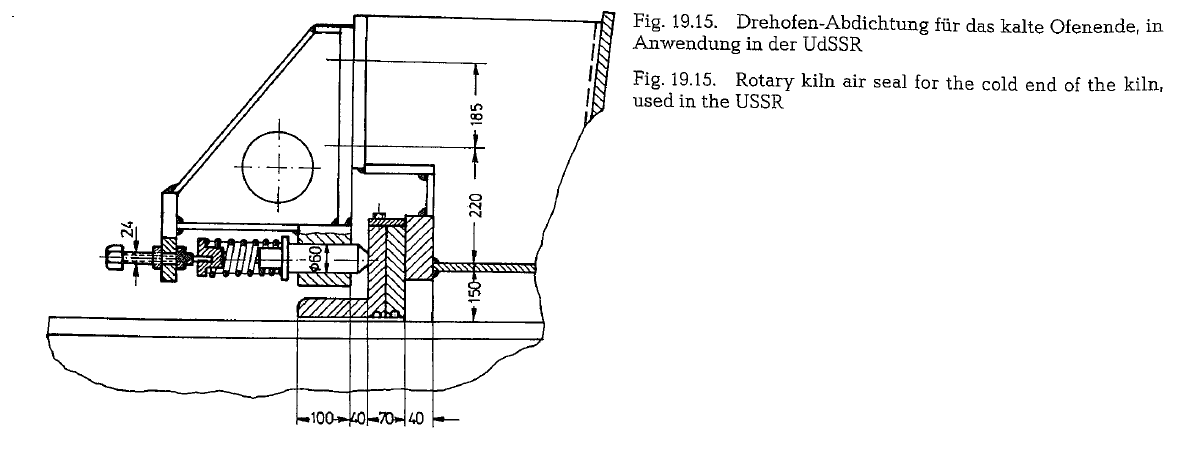
A less composite modification of an air seal is employed for the cold end of the Soviet 5 x 185m wet process rotary kiln; this air seal is shown in Fig. 19.15.
Relative motion of kiln riding rings
As is known, kiln riding rings are not fixed to the kiln shell; they are of full floating design, to absorb the heat expansion of the kiln shell. This is of special importance in the area of the hot kiln end. An insuffi cient clearance between kiln shell and riding ring can cause a constriction of the kiln shell, resulting in damage to the kiln lining in the area of the riding rings; a further consequence can be the formation of cracks of the kiln shell. These loose riding rings per form a relative motion in relation to the kiln shell. Decreasing or stoppage of this relative motion is a warning of danger that a constriction of the kiln shell is imminent. Therefore, arrangements were devel oped to keep the relative motion within certain lim its, by measuring the relative motion, to prevent jam ming of the riding ring to the kiln shell. When apply ing a water spray device for water cooling of the kiln shell underneath the riding ring, the dangerous con striction of the kiln shell caused by the riding ring,
can be avoided. Care should be taken for proper lubri cation between riding ring and filler bars attached to the kiln shell, to prevent damages of the filler bars as well as of the riding ring. Recently, this problem became particularly acute with the introduction of large diameter rotary kilns.
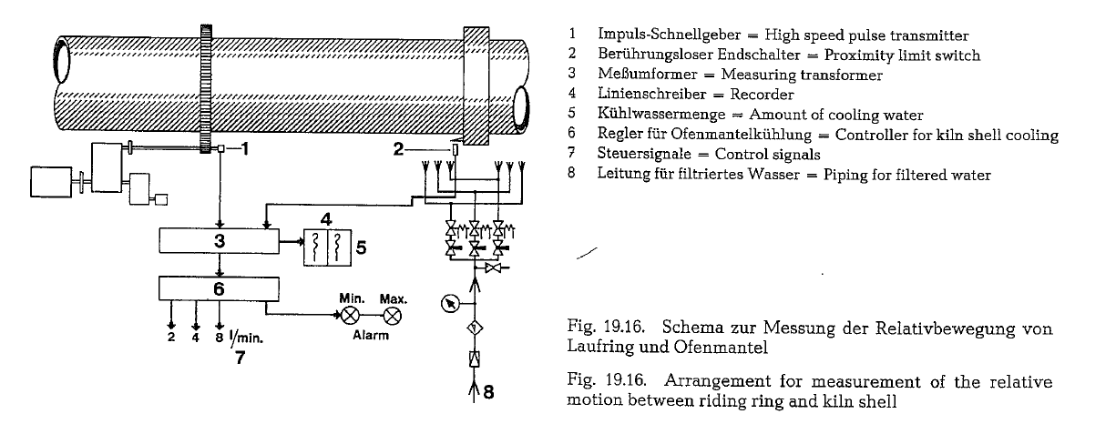
The F. L. Smidth Co. developed an electronic arrange ment for continuous measurement of the relative motion between riding ring and kiln shelL The princi ple of this arrangement is shown in Fig. 19.16.
A proximity limit switch is fixed to a pole at the side of the riding ring. This switch releases one pulse per revolution of the riding ring, and these pulses con ol the counting periods of the measuring transformer. On the kiln drive a high speed pulse transmitter is positioned, which releases approximately 20,000 pul ses per kiln revolution. The measuring transformer counts the number of pulses received from the pulse transmitter during one revolution of the riding ring, and the number of pulses received during one revolu tion of the” kiln shelL The difference between these two measured values is proportionate to the relative motion of the riding ring; this is displayed by the measuring transformer as well as by a recorder, which is connected to the output signal (0-10 V, DC). This output signal is also transmitted to the control ler, which releases control signals for the water spray arrangement, and alarm signals for maximum and minimum relative motion of the riding ring.
Filtered water is sprayed on the kiln shell through 2 x 3 sets of nozzles. The water spray arrangement is controlled by three solenoid valves through an elec tronic device, which is connected to the transmitter box [191a, 87c].
Riding rings weighing more than 100 metric tons are too heavy to handle during transportation and erec tion; therefore, they are divided into two identical. parallel rings, which are assembled in contact with each other. Despite their same shape, both rings show during operation a small relative movement; there fore, the contacting surfaces of these two rings, are also designed for lubrication [191b].
Self-adjusting supporting rollers
The decisive parameter for sizing of supporting roll ers is the Hertz pressure between supporting roller and the riding ring, measured in kg/em2. Assuming unyielding roller surfaces, the theoretical contact area is a straight line. In practice however, both sur faces are deformed by the pressure, so that the area of contact becomes an almost plane rectangle. Riding rings and supporting rollers are so amply sized that this deformation is kept far below the limit of elastic ity.
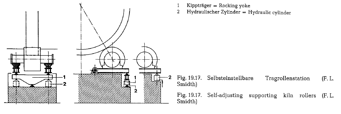
To keep the contact line always straight, the F. L. Smidth Co. developed a self-adjusting roller support construction. This system is based on the condition that to ensure the linear contact between roller shaft and bearing, the journal bearings are supplied with ball sockets (see Fig. 19.17.). Each bearing rests on a hinged supported bedplate.
The mutual balancing takes place either:
- Mechanically, e. by applying a rocking yoke, where the three supporting points are designed as bridge bearings (elastomer lamellas vulcanized between two steel plates).
- Hydraulically, e. resting on two interconnected cylinders, or alternatively coupled with a rocking yoke as a safety precaution against possible hydraulic failure.
Regardless of the operating conditions, this design ensures a full contact between riding ring and sup porting roller. It allows an even distribution of the surface pressure (Hertz pressure) over the toal width of the riding ring. As a result, the originally calcu lated Hertz pressure can be increased, allowing for a reduction in the dimensions of the riding ring and roller. Despite the increased number of components, this design is – according to the manufacturer – lower in price than the conventional fixed support construction.
Firing of the rotary kiln
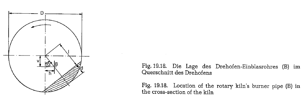
Arrangement of the burner pipe
The burner pipe can be aligned either parallel to the kiln’s longitudinal axis or parallel to the burner floor. In the latter case, the burner pipe is inclined to the kiln axts and to the material bed respectively; due to collision of the flame with the material bed, this posi tion of the burner pipe does not always contribute to good burning results.
Generally, the burner pipe is positioned in the center of the rotary kiln’s cross-section. But there are also modifications, especially in large diameter rotary kilns, where the location of the burner pipe is closer to the surface of the material bed and parallel to the kiln’s longitudinal axis, thus to prevent an inclination of the burner pipe towards the material.
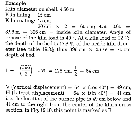
The following example deals with positioning of the burner pipe outside the center of the rotary kiln’s cross-section.
The coal dust burner
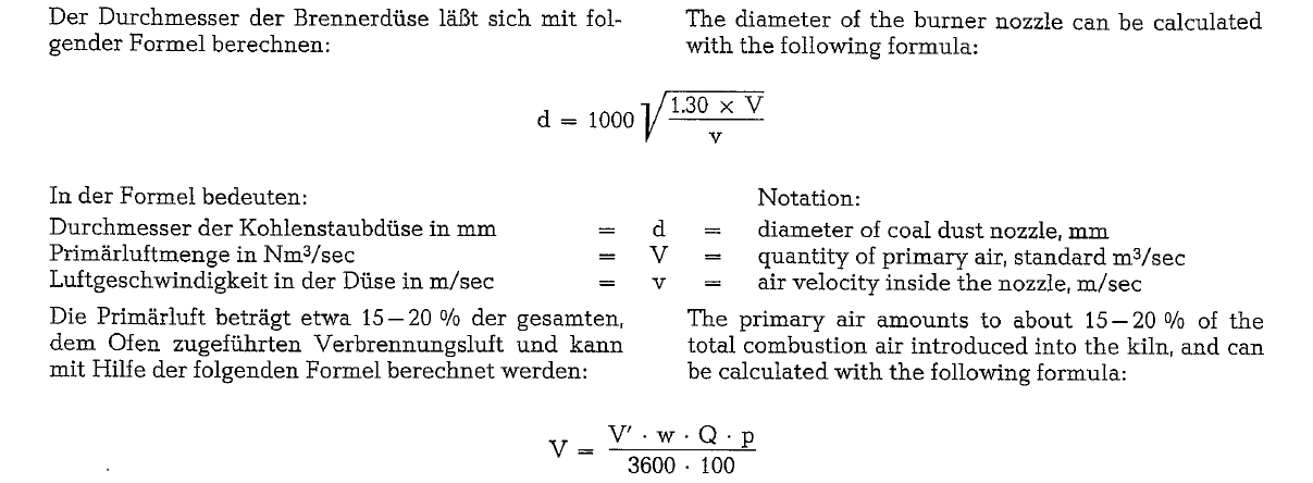
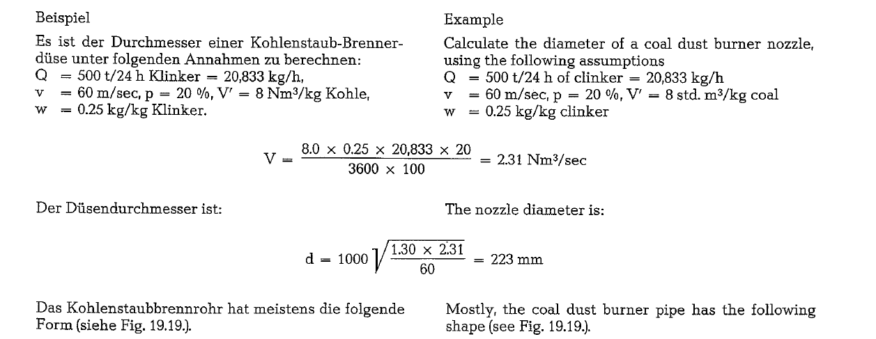
The diameter calculated in the above example refers to the marked piece of the burner pipe shown in Fig. 19.19.
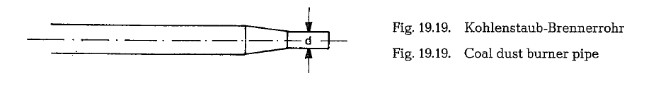
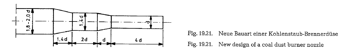
Narrowing the outlet of the burner pipe results in a better mixing of the coal dust-air compound. Also, changing the nozzle diameter allows to control the velocity of the primary air-coal dust mixture. Generally, the following rule is valid: the higher the veloc ity in the nozzle, the shorter and more intensive is the coal dust flame. The velocity of the primary air coal dust mixture is a function of the kiln capacity or of the kiln diameter respectively.
The diagram presented in Fig. 19.20. shows the rotary kiln’s diameter with the indication of the correspond ing velocity in the burner nozzle. These nozzle veloci ties result in optimal flame shapes, and cause, in this way, favorable conditions for heat exchange between the flame and the kiln feed.
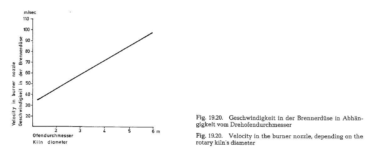
Good results were acquired with a newly developed coal dust burner [192], which is shown in Fig. 19.21. By thoroughly mixing of the coal dust with the primary air and by increased turbulence, this burner delivers a short intensive coal dust flame, resulting in a capa city increase of the rotary kiln.
In chapter “Fuels” it was already explained that the flame temperature increases with the temperature of the combustion air. Applied to the rotary kiln, this refers mainly to the temperature of the secondary air. Hot primary air is not an efficient carrier of the coal dust and therefore it might possibly impair the flame. Besides, the primary air fan limits the temperature of the primary air.
To prevent the burning away of the burner nozzle pit, the ignition of the coal dust flame should start at about 25 em from the nozzle rim, which can be acquired when applying the nozzle velocities shown diagrammatically in Fig. 19.20. Burning away of the nozzle and back-firing can occur, if the velocity in the coal dust nozzle decreases below 25-20 m/sec.
Ruhland formulated an equation in which he sum marized the rules required to calculate the length of a coal dust flame in a rotary kiln [192a].
Due to the tendency of the continuing fuel price increase even in the area of coal, the cement industry switched to the application of low quality coal with high ash content and low fractions of volatile consti tuents. Experience showed that the velocity in the burner nozzle depends not only upon the kiln diame ter, but also to a considerable degree upon the quality of the coal being used, especially upon the fineness of grinding.
The idea that an economic operation of the rotary kiln with this low quality coal is not possible, led to the application of a second fuel component. To satisfy this requirement, the Pillard Oil Firing Co., W Ger many, improved two special types of kiln burners; one for the combination of coal with fuel oil (type VR-K), and the other for the combination of coal with natural gas (type VR-GK). Pillard claims that a mini mum amount of primary air is required – in the region of 6 % of the total combustion air -for a wide range of flame adjustment.
The Pillard Burner Co. (Pillard Feuerungen GmbH. Taunusstein, W. Germany) developed recently (1984) a three-channel coal dust burner for the application of various solid fuels in rotary kilns. Taking into con sideration specific kiln conditions and fuel qualities it is – according to the manufacturer – possible to form any practically desired flame shape by stepless adjustment, even during kiln operation.
The design of the burner also allows the transition of the coal dust stream from circular cross-section to a ring-type cross-section. For start-up operations of rotary kilns the Pillard three-channel burner allows besides coal dust also the use of gaseous and liquid fuels from zero output to full capacity kiln operation.
Fig. 19.21.a. shows a partial cross-section of the Pillard three-channel coal dust burner.
Inside a central jacket pipe (1) nozzle pipes for liquid and gaseous fuels for start-up operation are located. From a concentric channel (2) flows clean air to generate a diverging and rotational component by the help of a movable whirling device. The coal dust air mixture is supplied by the concentric-channel (3). In the outer concentric channel (4) clean air flows over an axial body in an axially adjustable or low div erging direction respectively.
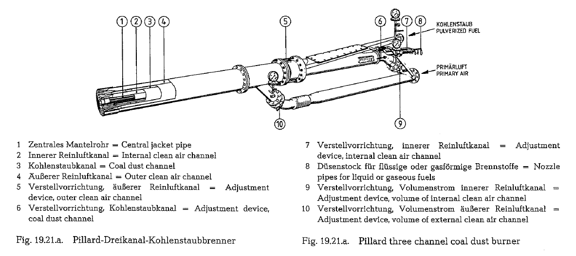
The velocities of the applied air streams can be step less regulated using the adjustment devices (5, 6, 7). The throttle valves (9, 10) are for regulation of the clean air streams.
Fuel oil burner
For fuel oil operated rotary kilns, the following oil burner or oil atomizer nozzles are in use:
The pressure oil atomizer; at fixed orifice, the oil throughput is controlled by variable
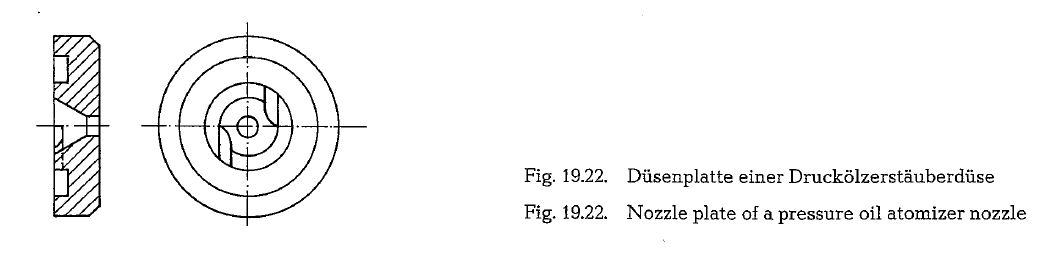
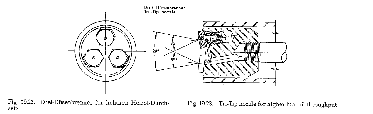
Fig. 19.22. shows the scheme of a pressure oil atom izer. The nozzle plate is furnished with tangential slots, which gives the oil a rotating movement. The pressure of the fuel oil is converted into kinetic energy. If e.g. the oil throughput has to be lowered to one third, then the pressure should be decreased to one ninth. For fuel oil No 6 (corresponding to fuel oil “S” according to German Standards DIN 51603/1963), an oil pressure of 142 psig is not sufficient for atomi zation. The operating pressure of pressure oil atomizers is about 1300 psig at 110 ac. The range of regulation is limited to a ratio of about 1 : 3. Low or high burner capacity can only be achieved by replacing the nozzles. For a high throughput of about 200 kg of fuel oil and more, multiple-tip nozzles as shown in Fig. 19.23. are employed.
Another type of pressure oil atomization is that with variable orifice and constant A horizontally displaceable core located centrally inside the nozzle inlet, reduces or increases the noz zle orifice, and by that the fuel oil quantity injected into the kiln. The operating pressure is about 285 psig. Also here, the range of regulation is limited.
Realizing the difficulties of the narrow control range at pressure oil atomization, the Pillard Oil Firing Co., W Germany. developed a special oil atomizer, which is controllable within a very wide range (type MY). With this atomizer it is possible during start-up oper ations, to switch one of the two oil supply lines to the oil return line. With this circuit even the largest kiln units can be started from the cold state up to normal operation, applying the regular burner operating dev ices.
Oil return burner
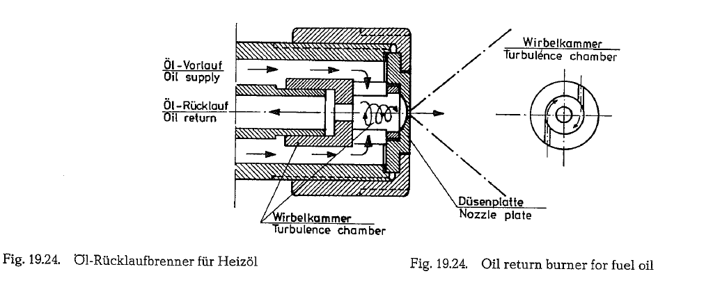
This burner nozzle allows for an adjustment with a turndown ratio of about 1 : 8; this is sufficient to start up the cold rotary kiln and for heating up to normal operation.
Fig. 19.24. shows a schematic of the oil return burner. The fuel oil comes through the tubular shell and through the tangential slots into the turbulence chamber; here, after getting into strong rotation, the oil is injected through the nozzle into the kiln. How ever, only one part of the fuel oil is injected through the nozzle orifice; the remaining part returns as oilThe quantitative division of the oil into oil supply and reflux is done by a control valve in the oil return line. The required pump capacity should be 30-50 Ofo above the maximum nozzle throughput. The operat ing pressure is in the range from 285 to 570 psig.
The Pillard two-channel burner
As to the air supply nozzles for rotary kiln fuel oil burners, the present development tends clearly towards the two-channel burner. The present state of the development is shown by the Pillard burner type VR.
In the air supply nozzle type VR, the primary air is supplied in two concentric channels. A whirling dev ice is located at the exit of the inner channel, which gives the internal air a rapid whirl. The external pri mary air is discharged axially. Adjustment of the mix ing of the two components allows for wide variations in the shape of the flame. Throttle valves distribute the primary air as required, during kiln operation, to either channel. The external primary air also serves the purpose of cooling the outer casing of the air noz zle. Besides, the outer casing of the air supply nozzle is usually protected from overheating by a refractory insulation (see Fig. 19.25.)
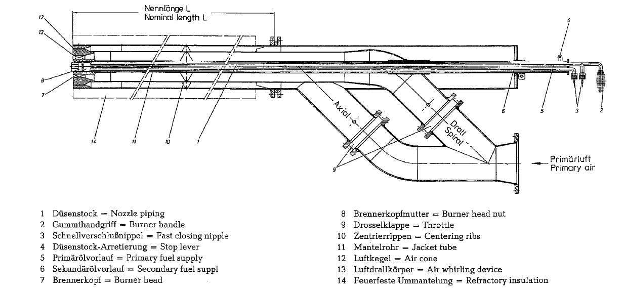
Fig. 19.25. Pillard two-channel burner, type VR
Ultrasonic burner
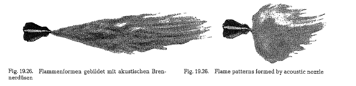
The so-called Ultrasonic burner [194] provides the means for shaping the fuel oil flame in wider limits. Acoustic nozzles using sound waves generated by either compressed air or steam at 90 psi, atomize the fuel oil to uniform particles of any desired size, with the possibility to produce a wide variety of flame pat terns. Fig. 19.26. shows two extreme flame patterns, formed with the acoustic burner nozzle.
The acoustic nozzle consists of a supersonic gas noz zle, a resonator and a fuel nozzle. Fig. 19.27. shows a schematic of this burner.
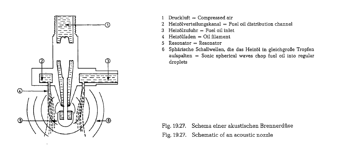
Depending on the burner model. the resonator vibrates with 10,000-20,000 Hz, thus creating an oil mist with oil particles of 5 micron diameter. The range of flow control is 1 : 15. Here the noise level might be a problem, since kiln operators are required to wear protective ear muffs. Actually, this is not an ultrasonic operation. To be ultrasonic, the frequency of vibration must be above 30,000 Hz, i.e. beyond the limit of audibility.
Burner for natural gas
The most common burner for natural gas in the U.S. cement industry is the plain burner pipe with only one channel for the gas, without the use of primary air, which is not required for the combustion of this fuel in the rotary kiln.
The high nozzle outlet velocity of the natural gas of 300-400 m/sec causes an intensive intake of the hot air from the clinker cooler and an instant thorough mixing with the gas which makes the use of primary air redundant. Consequently, the investment as well as the operating costs of the primary air fan can be saved. Simultaneously, heat expenditures required for heating of the primary air can be avoided. Thus, complete combustion of the gas can be attained with out expensive excess air. The ignition of the flame starts about 50 em from the rim of the nozzle.
At the gas burner which is schematically shown in Fig. 19.28. the flame length as well as the exit velocity of the gas from the nozzle are controlled by displace ment of the core inside the nozzle, thereby varying the cross-section of the nozzle’s orifice. Also the con tour of the core is of importance of the shape of the flame. The elongated nozzle core with rounded edges as shown in the picture forms a flame which is more elongated. Shorter nozzle cores with sharp formed edges, result in turbulent wide-angular, and thus, short flames.
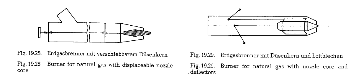
The nozzle core shown in Fig. 19.29. is furnished with curved deflectors, to give the emerging gas-stream a twist with the aim of further shortening the flame in this way. In this burner, the nozzle core and the deflectors are displaceable independently of each other. Nozzle orifices with diameters from about 70-120 mm are in use with cores to control the cross-section. The operating gas pressure is 35 psig
The Pillard Oil Firing Co., W Germany, reports good results with the newly developed natural gas burner system VR-G. In this burner, the gas stream is divided into at least two components, which are adjustable independently of each other. This system satisfies the demand for an optimum adaptation of the heat supply to the process requirements of the rotary kiln arrangement.
Feed preparation methods for rotary kilns
Two fundamental methods are known for the prepar ation of the feed for rotary kilns:
- The wet process; slurry with a water content of approximately 18-45 % is prepared in washmills, by wet grinding, or by a combination of both procedures.If the physical properties of the raw material com ponents (plastic clay, chalk with high moisture content, etc.) do not allow an economical prepara tion of dry raw mix, the application of the wet pro cess is indispensable.
- The dry process, where the dry state of the raw material components is exploited to prepare the raw mix.
According to the preparation processes quoted under items a. and b., the following rotary kiln burning pro cesses are applied:
- Wetprocess
- The long wet process rotary kiln with internal heat exchangers such as chains, segments or other
- The short wet process rotary kiln without internal installations, working in conjunction with a heat exchanger for partial drying of the These heat exchangers are known under the terms “”slurry dryer””, “concentrator”” and “calcinator””.
- The medium long wet process rotary kiln with preliminary mechanical dewatering of the slurry by suction or pressure For disintegration and final drying of the filter cake fed into the rotary kiln with a moisture content of 15-20 %, the kiln is furnished with a short chain section.
- The short wet process rotary kiln without internal installations with mechanical preliminary dewa tering of the The resulting filter cake is then processed to nodules. These are fed into a preheater, e.g. a shaft type preheater (Davis pre heater), or to a heat exchanger grate (Polysius Lepol grate).
- Dry process
- The long dry process rotary kiln without internal
- The long dry process rotary kiln with internal heat exchangers, such as chains, refractory bridges,
- The short dry process rotary kiln working in con junction with preheaters, such as suspension pre heaters or LepolThe dry process rotary kiln with waste heat boiler.
Comparison between dry and wet process
The basic advantage of the dry production method over the wet process, is the lower specific heat con sumption for clinker burning.
When deciding which production method to select for a new project, it should be realized that there is no general valid rule, because of the absence of a uni form method for a comparable appraisal of the effecquently the impossibility of proving unequivocally the superiority of one over the other method.
For this purpose, Soviet experts developed a formula which tells in what case the wet or dry process can be economically applied. However, the factors used in this formula are based on charge prices of the socia listic planned economy, and are therefore not appli cable in the domain of the competitive economy.
Previously, clinker produced by the wet method was considered to be of higher quality and uniformity, because of the better homogenization of the raw com ponents in the state of slurry. Now, highly sophisti cated pneumatic homogenizing machinery and meth ods for dry raw mix, allow the preparation of the raw mix with the same degree of uniformity as raw mix prepared by the wet method. There is no difference in the quality of the clinker.
However, Soviet experts claim that in the drying sec tion of the wet process kiln, besides the physical pro cess of water vaporization, there also occurs a weak ening in the bond of the crystal lattice. This results in an accelerated clinker of the crystal lattice. This results in an accelerated clinker formation during the burning process. It is said that this is the reason why sometimes the quality of wet process cements is superior to that of dry process cements.
Proportioning of dry raw material components to the required composition is much easier than proportion ing of moist, wet or plastic raw material components [197]. It is known that grinding of slurry requires a lower grinding cost. When grinding the same mater ial to the same fineness, dry grinding requires approximately 30 % more energy than wet grinding. However, this advantage is neutralized by the fact that the dry grinding wear rate of mill liners and grinding media is only 30- 40 % of the wet grinding wear rate. Thus the higher wet grinding wear rate off sets the cost of higher energy consumption of dry grinding of the raw mix.
A wet process cement plant requires about 20 % more silo volume for slurry storage, compared to the raw mix silo volume of a dry process cement plant with equal capacity.
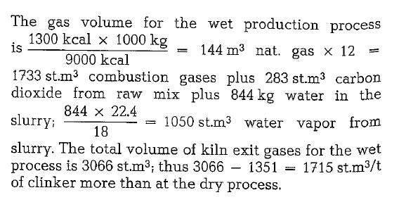
A conventional heat comsumption figure for the wet production process is 1300 kcal/kg of clinker, where as the heat consumption figure for the dry process
The volume of the kiln exit gases per ton of clinker in the dry production process is 89m3 nat. gas x 12 = 1068 st.m3 combustion gases plus 283 st.m3 carbon dioxide from raw mix, thus a total of 1351 st.m3 per ton.
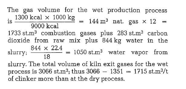
To produce e. g. 2000 mt/24 h of clinker, the raw material department of the dry process cement plant must handle 2000 x 1.6 = 3200 t/24 h of cement raw mix, whereas in a wet process cement plant the weight of the water in the slurry is 2000 x 0.844 = 1760 t/24 h more than in a dry process cement plant. This results in higher energy consumption.
Presently erected wet process rotary kilns whose design is influenced by raw material properties, are large units with approximate sizes of 5 m diameter and 160-200 m length. These kilns are equipped with expensive chain sections in the price range of $ 100,000.- Chains are difficult to handle, especially during kiln shut down operations and power black outs.
The sizes of larger capacity dry process kilns, work ing in conjunction with raw mix suspension preheat ers, vary from approximately 4 x 60 m to 5 x 80 m depending on production capacity. Generally, it can be said that for the same production capacity, the price of a short dry process rotary kiln with suspen sion preheater is the same as the price of a long wet rotary kiln with internal heat exchangers.
Presently, the dry cement production method is the most economical one. Of course, if there are basic raw material components consisting of high plastic chalk and clay with about 15-20 % natural moisture, easy to suspend in wash-mills, and if only low grinding energy is required, the wet process may be adopted.
In the U.S., 54% (1983) [141a] of the total cement prod uction is by the dry method. The number of dry pro cess cement plants is increasing. In Mexico, 97 % of the cement output is produced dry; in Japan, the cor responding figure is 65 %. In the Federal Republic of Germany, 92 % of the cement production comes from dry process cement plants; from 1952 to the present time, the number of wet process cement plants dropped by 18 %. The Soviet Union, traditionally the country of wet process manufacturing, with 88 % wet process cement plants, recently started a long range program for conversion to the dry production proquently the impossibility of proving unequivocally the superiority of one over the other method.
For this purpose, Soviet experts developed a formula which tells in what case the wet or dry process can be economically applied. However, the factors used in this formula are based on charge prices of the socia listic planned economy, and are therefore not appli cable in the domain of the competitive economy.
Previously, clinker produced by the wet method was considered to be of higher quality and uniformity, because of the better homogenization of the raw com ponents in the state of slurry. Now, highly sophisti cated pneumatic homogenizing machinery and meth ods for dry raw mix, allow the preparation of the raw mix with the same degree of uniformity as raw mix prepared by the wet method. There is no difference in the quality of the clinker.
However, Soviet experts claim that in the drying sec tion of the wet process kiln, besides the physical pro cess of water vaporization, there also occurs a weak ening in the bond of the crystal lattice. This results in an accelerated clinker of the crystal lattice. This results in an accelerated clinker formation during the burning process. It is said that this is the reason why sometimes the quality of wet process cements is superior to that of dry process cements
Proportioning of dry raw material components to the required composition is much easier than proportion ing of moist, wet or plastic raw material components [197]. It is known that grinding of slurry requires a lower grinding cost. When grinding the same mater ial to the same fineness, dry grinding requires approximately 30 0/o more energy than wet grinding. However, this advantage is neutralized by the fact that the dry grinding wear rate of mill liners and grinding media is only 30- 40 % of the wet grinding wear rate. Thus the higher wet grinding wear rate off sets the cost of higher energy consumption of dry grinding of the raw mix.
A wet process cement plant requires about 20 % more silo volume for slurry storage, compared to the raw mix silo volume of a dry process cement plant with equal capacity.
A conventional heat comsumption figure for the wet production process is 1300 kcal/kg of clinker, where as the heat consumption figure for the dry process
The volume of the kiln exit gases per ton of clinker in the dry production process is 89m3 nat. gas x 12 = 1068 st.m3 combustion gases plus 283 st.m3 carbon dioxide from raw mix, thus a total of 1351 st.m3 per ton.
To produce e. g. 2000 mt/24 h of clinker, the raw material department of the dry process cement plant must handle 2000 x 1.6 = 3200 t/24 h of cement raw mix, whereas in a wet process cement plant the weight of the water in the slurry is 2000 x 0.844 =1760 t/24 h more than in a dry process cement plant. This results in higher energy consumption.
Presently erected wet process rotary kilns whose design is influenced by raw material properties, are large units with approximate sizes of 5 m diameter and 160-200 m length. These kilns are equipped with expensive chain sections in the price range of $ 100,000.- Chains are difficult to handle, especially during kiln shut down operations and power black outs.
The sizes of larger capacity dry process kilns, work ing in conjunction with raw mix suspension preheat ers, vary from approximately 4 x 60 m to 5 x 80 rn depending on production capacity. Generally, it can be said that for the same production capacity, the price of a short dry process rotary kiln with suspen sion preheater is the same as the price of a long wet rotary kiln with internal heat exchangers.
Presently, the dry cement production method is the most economical one. Of course, if there are basic raw material components consisting of high plastic chalk and clay with about 15-20 % natural moisture, easy to suspend in wash-mills, and if only low grinding energy is required, the wet process may be adopted.
In the U.S., 54 % (1983) [141a] of the total cement prod uction is by the dry method. The number of dry pro cess cement plants is increasing. In Mexico, 97 % of the cement output is produced dry; in Japan, the cor responding figure is 65 %. In the Federal Republic of Germany, 92 % of the cement production comes from dry process cement plants; from 1952 to the present time, the number of wet process cement plants dropped by 18 %. The Soviet Union, traditionally the country of wet process manufacturing, with 88 % wet process cement plants, recently started a long range program for conversion to the dry production process.
Rotary kiln capacity
The variety of the rotary kiln systems, burning meth ods, and influencing factors makes it difficult to establish kiln capacity formulas. For practical pur poses of rotary kiln sizing, statistical data for each kiln system are used to derive capacity figures which are applied as indicating factors.
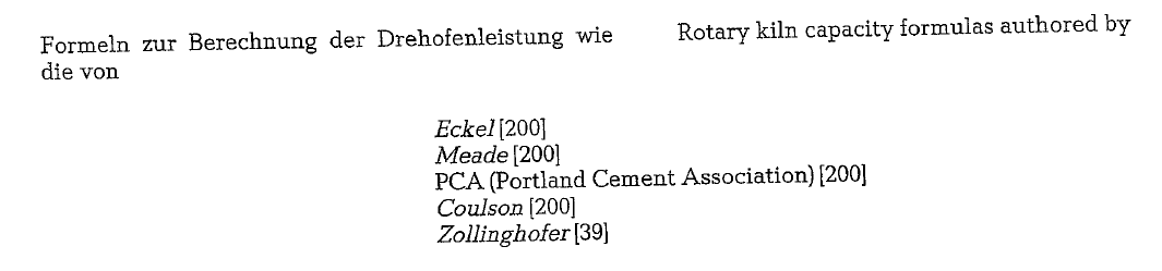
are based on geometrical dimensions of the rotary kiln.
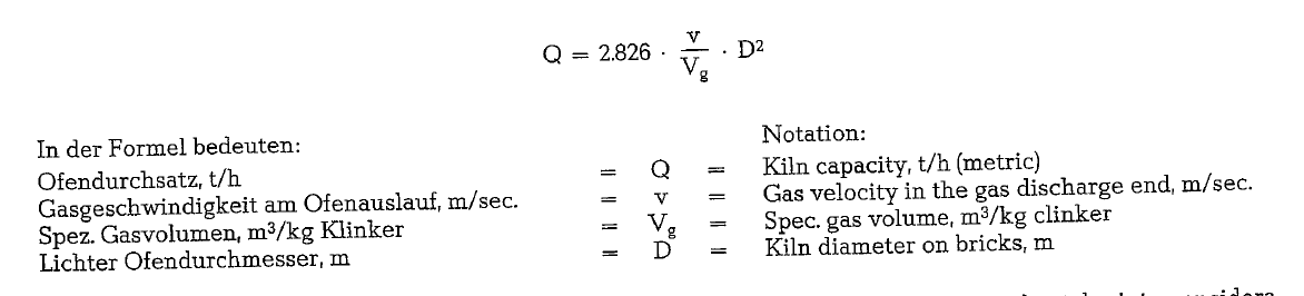
Since the kiln capacity formulas take into considera tion only a fraction of the factors influencing the rotary kiln’s capacity, they have merely limited appli cation.
Chodorow[202] developed a kiln capacity formula for wet process kilns, which was accepted for production planning calculations by the Cement Industry Insti tute of the Soviet Union. This formula reads:
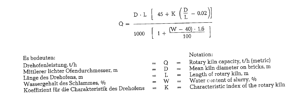
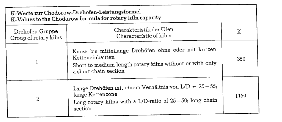
This index is defined in the following table.
To compare the operation of rotary kilns, formulas for the following criteria can be applied:
- The heat capacity of the rotary kiln; this is the quantity of heat per unit of time which can be generated in the burning zone of the rotary The heat capacity formula (according to Chodo roW)reads:
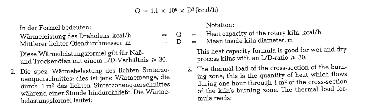
2-The thermal load of the cross-section of the burn ing zone; this is the quantity of heat which flows during one hour through 1m2 of the cross-section of the kiln’s burning The thermal load for mula reads:
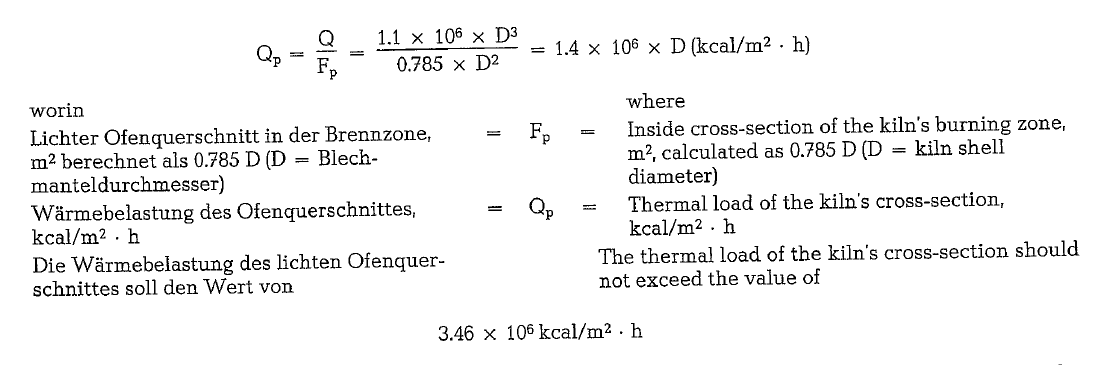
This figure results from the gas velocity in the kiln’s burning zone; based on an economical heat exchange between gas and material, the gas veloc ity should not exceed 8.6 m/sec. Wet process kilns fed with slurry containing a high percentage of water, need more heat for slurry drying; in this case more excess air is used for burning, and therefore the gas velocity in the burning zone will exceed the quoted figure of 8.6 m/sec, and will approach a velocity of 10m/sec. High gas veloci ties do not only impair the heat transfer, but also cause high carry over of dust from the kiln load. It should be noted that the dust concentration in the kiln gas increases with the third power of the gas velocity.
3-The thermal load of the burning zone; this repre sents that heat quantity which is generated in one hour per cubic meter of burning zone space. For this, the length of the burning zone should be known. This can be inferred from the diagram shown in Fig. 19.30. The length of the burning zone varies with the specific heat consumption for clinker burning.
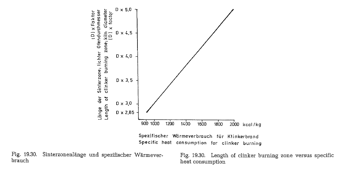
It is known from practical experience that the ther mal load in the burning zone amounts to approxi mately 300,000 kcal!m3 · h. This is an orientation figure which can vary by ± 10 %. This value can be considered as an invariable magnitude, since experi ments with the aim to increase this figure applying forced kiln operation result in high exit gas tempera tures, and high gas velocities, thus missing the goal.
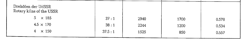
19.3.2.1. Long wet process rotary kilns – Sizes and capacity figures
Table 19.9. contains sizes and capacity figures for long wet process rotary kilns.
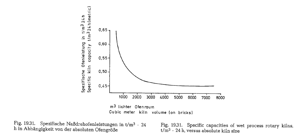
The table demonstrates that the specific capacity figure of long wet process kilns is on the average 0.526 t/m3 · 24 h. The kiln lining was taken into consideration when calculating the kiln volume. The spe cific rotary kiln capacity is a function of the kiln’s absolute size. Older, small size wet process rotary kilns, not listed in the above table, with a volume of about 500 m3, show high specific capacities of 0.65 t/m3 · 24 h. New large wet process rotary kilns how ever, with volumes of 7500- 8000 m3, show specific capacities of 0.45 t/m3 · 24 h. This correlation is shown in Fig. 19.31.
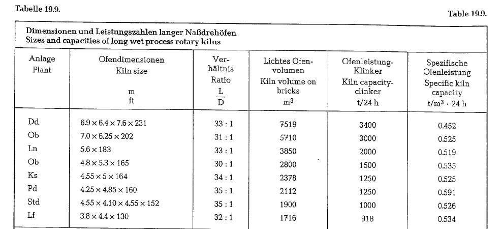
The Length : Diameter (LID) ratio of long wet process rotary kilns is on the average 33 : 1. The specific heat consumption of long wet process rotary kilns is in the range of about 1300-1650 kcal/kg of clinker, depend ing on the water content of the slurry, as well as on other influencing factors as chemistry of the raw material, quality of the fuel, etc. When compared to short wet process rotary kilns of older constructions, long wet process rotary kilns are operated with fuel savings of about 400- 700 kcal/kg. At long wet pro cess rotary kilns the exit gas temperature is about 150-230 o C. The dust concentration of normally operated long wet process kilns is approximately 15 grams/m3.
The power input of long wet process rotary kilns is about 17-27 HPh/t of clinker counted from the slurry silo down to the discharge of the clinker into the grate cooler. To speed up slurry drying, all wet process rotary kilns are equipped with internal heat exchangers, mostly with chain sections. The pressure drop of long wet process kilns with chain systems amounts to approximately 150-180 mm W.C.
19.3.2.2. Data of wet process rotary kilns of the USSR
The following contains characteristic data of some standard sizes of wet process rotary kilns manufac tured in the USSR.
- Wet process rotary kiln 4 x 150m; LID = 5: 1 Slurry contains 36 % water
Kiln slope: 4 %
Production: 850 t/24 h Revolutions: 0.57-1.14 rpm
Circumferential speed of kiln shell: 21-24 em/sec
Number of riding rings: 7 Length of chain section: 32.5 m Kiln drive motor: 430 HP
Kiln volume on shell: 1884 m3 Kiln volume on bricks: 1525 m3
Kiln weight: 1652 t
Weight of kiln lining: 794 t Tickness of kiln shell: 32 mm
Thickness of kiln shell under riding ring: 50 mm
- Wet process rotary kiln 5 x 170 m; LID = 38 : 1 Slurry contains 38 0/o water
Kiln slope: 4 %
Production: 1200 mt/24 h
Revolutions: 1.35 rpm
Circumferential speed of kiln shell: 32 em/sec
Number of riding rings: 7
Size of riding rings: 5400 x 700 mm (6) Size of riding rings: 5500 x 800 mm ( 1) Weight of riding rings: 36.3 t (6); 44.6 t (1)
Gear ring: 7000 x 700 mm; weight: 74.8 t
Kiln drive: 2 x 335 HP
Kiln volume on shell: 2703 m3 Kiln volume on bricks: 2244 m3
Chain section: 220 t of chains with
4065 m2 of chain surface
Kiln weight: 2262 t; kiln shell as such: 990 t Heat consumption: 1550 kcal/kg
3-Wet process rotary kiln; 5 x 185m; LID = 37: 1 Slurry contains 38 0/o water
Kiln slope: 3.5 0/o
Production: 1700 t/24 h
Revolutions: 0.4- 1.24 rpm; regular operation
1.22 rpm
Circumferential speed of kiln shell: 15.7-32 em/sec
Number of riding rings: 8
Kiln drive motors: 2 x 415 HP Volume on shell: 3631 m3 Volume on bricks: 2940 m3
Heat consumption: 1585 kcal/kg
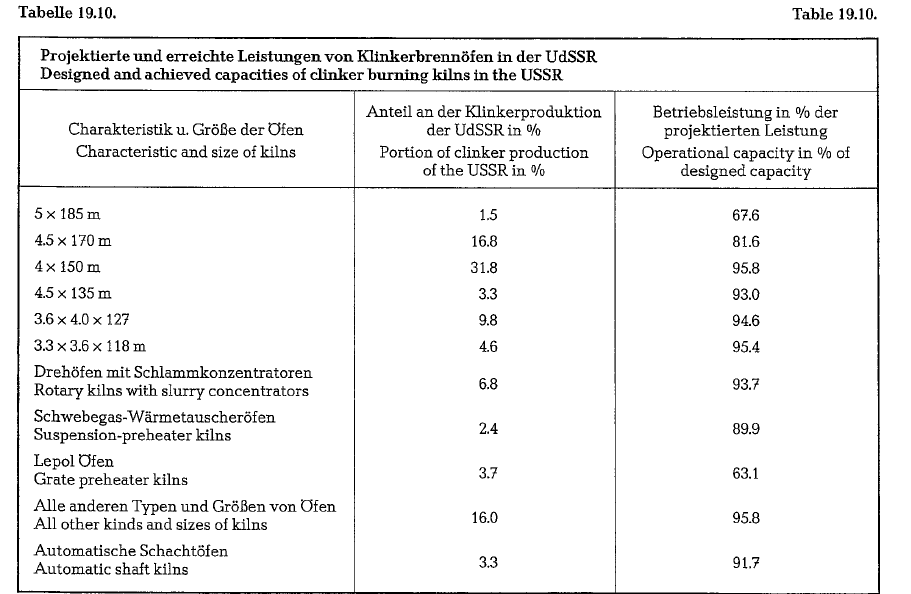
The above cited capacities of the three types of Soviet wet process kilns however, were not achieved by all installed kilns. Table 19.10. contains data about designed and operationally achieved capacities, not only of the kilns cited here, but also of wet process kilns of other sizes as well as of dry process kilns and also of shaft kilns.
The short rotary kiln (Pyrorapid-kiln of the KHD Humboldt WedagAG)
Looking back at the development of the clinker burn ing process during the last 50 years, we find that the goal has been always the specific reduction in size of the rotary kiln itself. It is the logical conclusion due to the fact that this aggregate makes the clinker burning process possible, however at high operating cost.
Step by step such process functions as preheating the raw mix, dehydrating of the clay, decarbonization of the calcium carbonate were shifted to other aggre gates. Milestones in this development are the travel ling grate preheater, the suspension preheater, and the suspension preheater with precalciner. The addi tion of a calciner to the suspension preheater system makes it possible to decarbonate the raw mix almost totally, and to preheat it at the same time to about 900 oc.
Shifting the decabonization reaction from the rotary kiln (reaction time in minutes) to the suspension pre heater (reaction time in seconds) has, in addition, the advantage of a fast sintering reaction, as the fast cal cined hot raw mix shows a higher reactivity. The time necessary to complete this clinker forming reaction is shortened (rapid burning).
However, this advantage is lost if the temperature of the hot raw mix is not immediate.ly elevated to sin tering temperature by being too long in the transition zone of the rotary kiln. The short rotary kiln (LID = 10-12) fits such cases much better than the normal length rotary kiln.
The effects of the fast formation of the clinker miner als in the short rotary kiln are:
- Grindability is The highly reactive · decomposition products of the raw mix compo nents eliminate the hard sintering of the clinker granules.
- The alite crystalls remain This improves the high early strength characteristics of the cement, reducing the grinding costs as compared to slowly burned clinker having the same lime standard.
- Conversely, for the same strength development, the lime standard can be lower if burned
- The influence of accessory components such as alkalies, sulfates, fluorides, and traces of heavy metals are not completely known; during rapid burning their activities could be
- According to the manufacturer, less noxious substances are emitted with the exhaust gases by the Pyrorapid kiln and, therefore, this kiln is more friendly to the This is also sup ported by the fifth stage of the cyclone preheater.
- Coating and plugging problems with the calciner and the preheater vessels, due to recirculation of particles, are less Often it is not necessary to install a gas bypass which raises the operating costs.
- The rapid burning system is unsuitable for clinker production destined for low alkali cement, if the sulfates and alkalies of the raw mix are so high that the installation of a gas bypass would be necessary.
The first Pyrorapid kiln system is in operation since March 1981 in a German cement plant
Slurry dewatering
There are generally two ways to reduce the water content in the slurry:
- Chemically, by addition of slurry thinners
- Mechanically, by slurry dewatering, using proper filters, e. drum or disc filters. Also filter presses are applied which form briquettes with a water content of about 18-20 %; however, this requires additional costs. Mechanical slurry dewatering allows for shortening of the long wet process kiln.
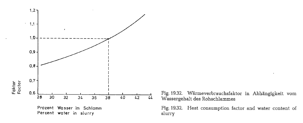
The diagram presented in Fig. 19.32. shows the pro portion between the water content of the slurry and the specific heat consumption
Thus e. g. a rotary kiln fed with slurry containing 38 % water, shows a specific heat consumption of 1500 kcal/kg of clinker. Lowering the water content of the slurry to 36 % would reduce the specific heat consumption to 1500 x 0.95 (factor) = 1425 kcal/kg, and vice versa, increasing the water content from 38 to 41 % would step up the specific heat consumption to 1500 x 1.08 = 1620 kcal/kg.
Chemical dewatering of slurry- Slurry thin ners
Cement slurry is a heterogeneous mixture of water and solids; the latter are present as very fine dis persed particles. This mixture has a specific viscosity which is measured by the size of propagation of the slurry on the Southard-plate. The viscosity of a well pumpable slurry corresponds to a diameter of 6- 6.5 em of the propagation on the Southard viscosi meter. A similar cement slurry viscosimeter is that of the F. L. Smidth Company.
Slurry thinners are added to the cement slurry to reduce the water content, simultaneously maintain ing the same viscosity.
Each percent of water reduction in the slurry increases the kiln capacity by about 1.5 %; simulta neously, the heat requirement for clinker burning drops by about 1 %.
Slurry thinners are fed into the raw mill; some of them work simultaneously as wet grinding aids.
The effect of the slurry thinners depends much on the physico-chemical properties of the slurry. The appropriate slurry thinner is experimentally ascer tained for each raw material or cement plant respec tively.
The correct concentration of the thinning agent in the slurry is of great importance. Each thinning agent is characterized by a peak concentration point; exceeding this point results in an increase of the slurry’s viscosity. Thus e. g. an addition of 0.33 % NaOH reduces the water requirement of a slurry from 40 to 34.6 %; after increasing the amount of NaOH however, the slurry becomes firmer.
The age of the slurry is also of importance; however, this can hardly be utilized in the plant”s operation. A freshly produced slurry of 40 % water had the same viscosity as a 7 days old slurry from the same raw material with a water content of 35.8 %. Coarser grinding results in a viscosity decrease of the slurry.
The ions and molecules of the slurry thinner are adsorbed on the surface of the raw mix particles in the slurry. The adsorption process prevents agglom eration of the particles, thus reducing the internal friction and increasing the flowability of the slurry.
There are two groups of slurry thinners:
- Alkaline electrolytes; sodium silicate (water glass), Na2Si03, sodium hydroxide, sodium car bonate (soda), Na 2C03•
- Surface-active, mostly organic substances: lignin derivatives, humic acids, sulfite liquor, calcium lignin-sulfonate, carbonaceous additives, molasses.
Calcium-lignin-sulfonate und sulfite liquor are byproducts of the paper industry. After pulping the wood with calcium sulfite and sulfur dioxide, the cel lulose remains undissolved, whereas the wood pulp forms the solution. The sulfite liquor so obtained is usually fermented and used for the production of alcohol. When treating the residue with calcium hydroxide, a product is obtained with contains up to 90 % of calcium-lignin-sulfonate. Depending on avail ability, either calcium-lignin-sulfonate or sulfite liq uor are used as slurry thinners.
In the USSR. sulfite liquor is much in use as a slurry thinner. An addition of 0.3- 0.4 % of the sulfite liquor concentrate (dry substance) related to the solids of the slurry, make it possible to reduce the water con tent in the slurry by 3- 4 %, and in some cases up to 8 %. Sulfite liquor seves simultaneously as a grinding aid.
A mixture of sulfite liquor and sodium carbonate (ratio 1 : 1) added to the slurry in an amount of 0.6- 0.8% (dry substance), reduces the water content of the slurry by 5-8%.
In one case, mentioned in the literature, an addition of 0.075 % Na2C03 made it possible to reduce the water content from 42 to 31.4 % without impairing the flowability of the slurry.
Sodium silicate in the amount of 0.1 % related to the dry matter of the slurry, reduced the water content from 35.5 to 24 %.
Sodium tripolyphosphate, Na5P3010, abbreviated STPP (a widely used detergent builder), when added in an amount of 0.8 % (related to the dry substance), reduced the water content of the slurry by 3 %; here it should be noted that soluble salts of calcium or magnesium which might possibly be present in the slurry, will tie up the phosphate and render it useless as a slurry thinner.
An increase in the pH-number functions also as slurry thinning; this results in higher concentration of the hydroxyl ions, which in this case work as deflocculants. This can be achieved by adding soda to the STPP.
Care should be taken when applying alkalies as slurry thinners because of the detrimental influence of the alkalies to the burning process as well as to the quality of the cement.
In each case, care must be taken to assure that the cost of the slurry thinner is lower than the savings resulting from reduced fuel consumption
Mechanical dewatering of slurry
Chain systems
Wet and dry process kilns have different chain sys tems; in the following, chains for both processes are discussed. In a dry process kiln, the only task of the chain system is the recuperation of heat between the hot kiln gases and the dry raw mix.
In addition to this, in wet process kilns the chain sys tem is in charge of evaporation, raw material trans port, and the prevention of mud rings.
Chain systems are not mechanical dewatering de vices in a true sense, but since they perform a sub stantial amount of mechanical work (in addition to the drying of the slurry) they are often classified as mechanical dewatering devices.
There are two different types of chain systems
- The chain curtain (Fig. 33.)
- The garland chains (Fig. 34.)
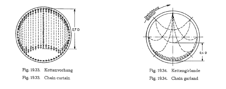
As chain curtains, the chains are attached only on one end. The length of the chains should be approxi mately 0.7 of the kiln’s internal diameter (see Fig. 19.33.). The distance of attachments of the partic ular chains along the circumference ist obout 30 em. In less dense chain curtains, a distance of 40- 45 em is applied. The distance between the rings is of the same size. The rings are arranged vertically to the kiln’s longitudinal axis. In the USSR. the chain cur tain is attached along a helical line.
The lowest point of the garland chain loop should be 0.4 D above the kiln’s lining (see Fig. 19.34.) Garland chains are attached on both ends, along a helical line, which with the kiln’s longitudinal axis forms an angle of 45- 60 o. In kilns with diameters up to 4 m, this angle should be 45- 50 o, and a 60 o angle should be applied in kilns with diameter above 4 m.
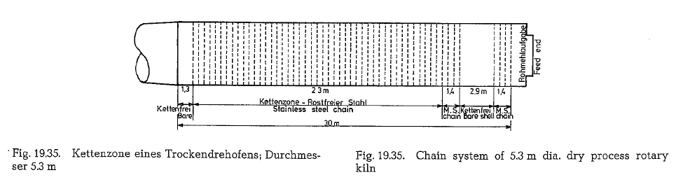
Dry process rotary kilns are normally supplied with chain curtains throughout (Fig. 19.35.).
One or two chainless sections are applied along the chain zone with the aim to:
- Equalize gas temperatures
- Serve as a buffer area to equalize varying rates of material transportation
- Precipitate kiln dust
- Allow for installation of thermocouples
Chain sections for wet process rotary kilns are a com bination of garland and curtain chains.
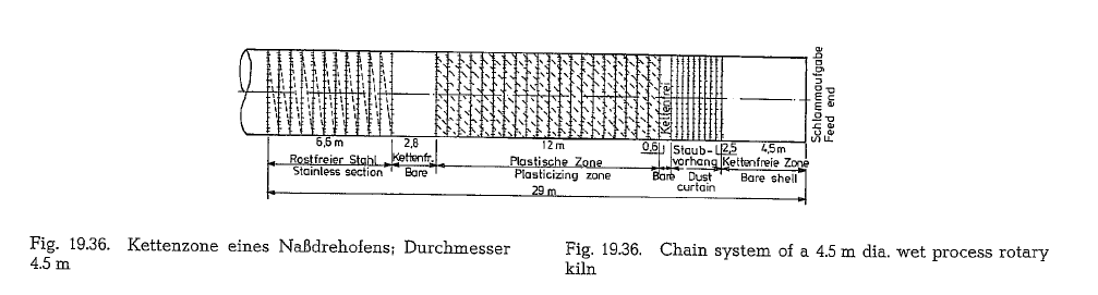
Fig. 19.36. Chain system of a 4.5 m dia. wet process rotary kiln
Garland chains convey the material in the kiln more efficiently than free hung chains; this is of special importance for wet process kilns. However, chain cur tains are easier and faster to install than garlands.
Further, it should be noticed that the slurry leaving the chain section should contain about 8- 10 OJo water, since lower water content promotes excessive dusting, due to disintegration of the granules.
Weight of chains
For a clinker production of 1 t/24 h the following chain weight is used:
- In wet process kilns 120 kg
- In dry process kilns 105- 110
By selecting the chains it should be noted that the following chain surface has to be apportioned to 1 m3
of chain section volume.
- In wet process kilns 6-8.5 m2/m3
- In dry process kilns 5-12 m2/m3
In this case the kiln volume means the volume of the chain zone.
Modern rotary kilns supplied with such chain sys tems will show the following heat consumption:
- Wet process kilns 1280- 1430 kcal/kg of clinker
- Dry process kilns 980- 1130 kcal/kg of clinker
A properly designed chain system can provide for a gain in fuel consumption of approximately 300 kcall kg of clinker, compared to kilns with less efficient heat exchangers.
It is a rule of experience that 1500 m of installed chain, reduce the kiln exit gas temperature by about 110 deg C.
The thermal effect of garland chains is 1.5 times higher than that of curtain chains of the same dens ity, i.e. 1m2 of garland chain surface evaporates per unit of time 50 % more water than curtain chains.
Chain sections in dry process kilns are not required to do the drying, thus kiln exit gas temperatures will be about 400 °C, compared to an exit gas temperature of about 200 o C for well designed chain sections in wet process kilns.
Chain material
For temperatures below 530 oc, steels should be selected that can be heat treated and hardened. How ever, the hardness so obtained, disappears at elevated temperatures. For temperatures from 530-640 oc, hardenable, high chromium stainless steel can be used.
For temperatures in the range from 640-800 oc 18 Cr 8 Ni stainless steel is recommended. For gas temperatures from 530-970 oc, No 309 or 310 (ASTM) stainless steel is recommended.
For application over 970 °C, an alloy with high chrome-nickel content, preferably of high hot strength should be used. High nickel alloy materials (over 20 %) are not used, because of their susceptibility to sulfur attacks. High chrome-nickel content provides for resistance against oxidation. Nevertheless, the oxygen content of the kiln gases should not exceed 2 %.
In reducing kiln atmosphere, hydrogen sulfide sev erly attacks the chains. Most chains fail through overheating.
The wear of chains in long wet process rotary kilns is in the range of 100-150 g/t of clinker. Long dry pro cess kilns show a chain wear rate of 80-120 g/t of clinker
Internal installations in wet process rotary kilns
Aside from chain sections, other classifications of internal heat exchangers in wet process rotary kilns include:
Slurry preheaters
Slurry dryers
Slurry preheater
Slurry preheaters inside rotary kilns are located before the chain section. A widely used slurry pre heater is that developed by the F. L. Smidth Co.; this preheater which is shown in Fig. 19.37. is also called the F. L. Smidth-slurry preheater.
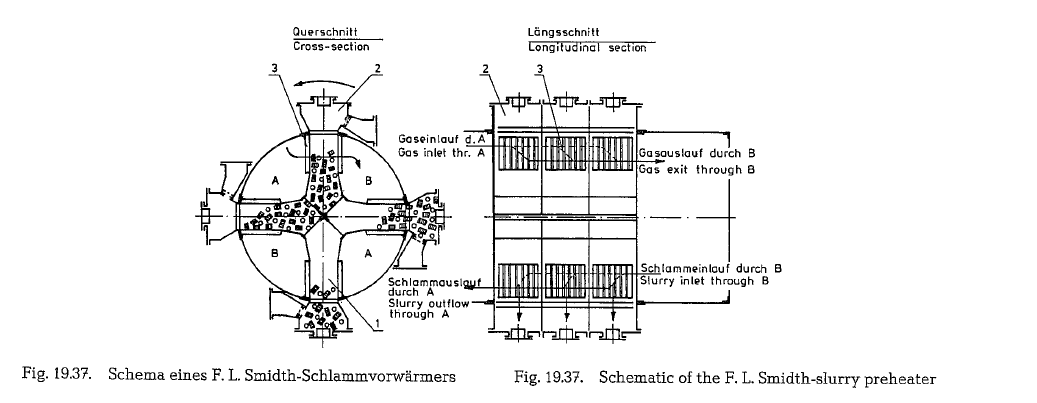
A metal cross (1) (see Fig. 19.37.) divides the kiln’s crossection into four compartments. Each two com partments located opposite, are designated A and B. Viewed from the slurry inlet, the A-compartments are covered with steel enclosures, whereas the B-compartments are covered at the opposite sides. The slurry entering the kiln, flows through compart ment B to the interoir of the cross which is filled with packing media. During the revolution of the kiln, the slurry is lifted by vessels (2) which protrude from the kiln shell. After a half revolution, the slurry flows into the compartments, and then into the kiln towads the chain section. The hot kiln gases enter the slurry preheater through the A-compartments and flow through the grid (3) into the B-compartments, from where, after passing a short section of the kiln, they leave the kiln at a low temperature. The gases pass the preheater in counter-current, and heat the slurry directly; also, the slurry is heated by the hot walls of the compartments as well as in contact with the pack ing media. The F. L. Smidth-slurry preheater heats the raw slurry from about 10-15 oc up to about 55-65 oc. This preheater serves simultaneously as a dust filter, since the kiln dust is precipitated in the slurry, thus remaining with the slurry in the kiln.
The slurry preheater shown in Fig. 19.38. works on a principle similar to the F. L. Smidth-preheater with the difference that here the kiln cross-section is div ided into six compartments.
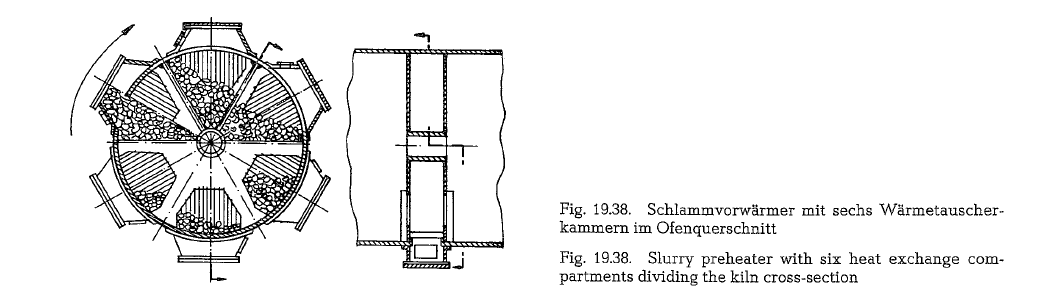
This slurry preheater is a Soviet innovation and was first employed in the Leningrad cement plant. The disadvantage of this slurry preheater consists in plug ging of the grid slots after a certain period of opera tion; to prevent this, about 2- 3 % water must be added to the slurry.
The slurry preheater shown in Fig. 19.39. works on another principle; here a chain curtain acts as a heat exchanger between the hot kiln gases and the slurry.
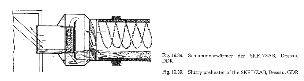
This slurry preheater was, in many cases, applied to the Soviet wet process rotary kiln of the size 4.5 x 170 m; the diameter is 5.5 m at a length of 2.35 m. The total chain length is 160m with a weight of 2.2 tons and a chain surface of 31 m2. This slurry preheater is manufactured by SKET/ZAB, Dessau, GDR.
Slurry dryers
In addition to chain sections which dehydrate the raw slurry to approximately 8- 10 % water content, in many cases special slurry dryers are inserted and located behind the chain section when viewed from the slurry inlet; after removing the remaining water content from the predried slurry, these slurry dryers simultaneously do the preheating of the dried raw mix.
Such a slurry dryer is shown in Fig. 19.40.; this is a so-called cellular heat exchanger which divides the kiln’s cross-section into seven compartments, thus achieving a better heat exchange between gas and solid material. The cellular heat exchanger, a development of the Soviet NII-Cernent Research Institute, was first applied in a 4.5 x 5 x 135 rn wet process rotary kiln of the Kuybyshev cement plant; the material is high heat resistant Cr-Ni-steel (25 % Cr and 6 % Ni). The cellular heat exchanger is inserted into the kiln in two 4.5 rn long sections each; its surface for the 5 rn diameter kiln is 380 rn2. The cellular heat exchanger is also applied in long dry process rotary kilns. It is more expensive than similar ceramic installations, but it causes a lower pressure drop.
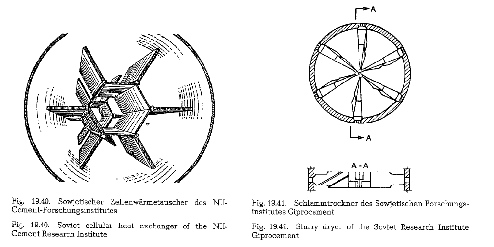
A slurry dryer developed by the Soviet Research Institute Giprocernent, is shown in Fig. 19.41.
Depending on the kiln’s length, 8-12 of these slurry dryers are built into the kiln. The main features of this slurry dryer are: Lifting of the kiln feed for better mixing with the kiln gases; heat transfer from the hot metal to the solid material. Also, a turbulent motion is imparted to the kiln gases, thus creating a more favorable heat transfer.
External heat exchangers for wet process rotary kilns
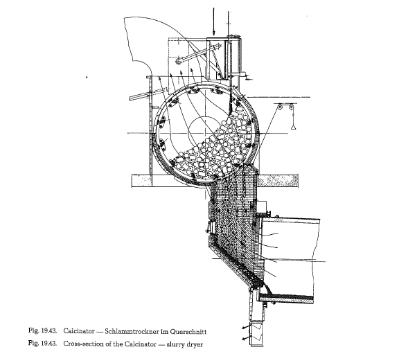
Additional products are available which preheat or dry the slurry outside the rotary kiln, e.g., the Calcinator of the 0 +K Orenstein + Koppel, Ennigerloh, Germany and the Concentrator of the Krupp Polysius, Beckum, West Germany.
The Calcinator consists generally of a rotating drum; the cylindrical part of the drum is covered by grates with uniform slots (see Fig. 19.42.).
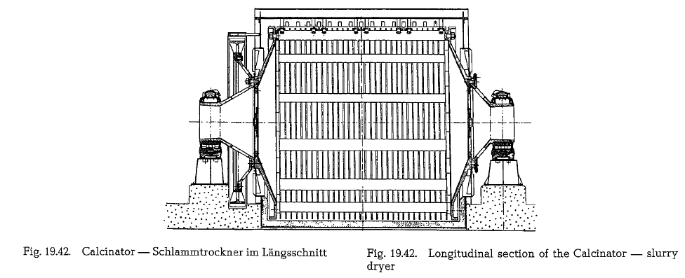
The drum is filled with packing media up to 50 % of its volume, and rotates, depending on the diameter, with a speed of 1.6- 1.1 rpm. The drum is enclosed by an insulated sheet metal housing. The slurry distribu tion device which disperses the slurry along the length of the drum is located on top of the housing.
The raw slurry with a water content of about 35- 45 %, flows from the distributing device through the grate slots into the drum, covering the hot surface of the filling media. Due to the slow rotation of the drum, the numerous tiny branched channels between the filling bodies are constantly changed. This results in an intensive exchange of heat between the slurry and the kiln exit gases. Fig. 19.43. shows the flow of slurry and of the gases through the calcinator drum.
The temperature of the gas leaving the Calcinator is approximately 125 a c. Due to the friction of the packing bodies against one another, the dried layer of slurry becomes detached, and is formed into nodules. The nodules thus produced, fall through the grate slots into the kiln. The residual moisture of the nodules is about 10-12 %.
The application of a Calcinator depends on the prop erties of the raw material. The raw slurry must have a certain plasticity, to guarantee the formation of nodules. Depending on the water content of the slurry, the heat consumption of wet process rotary kilns, working in conjunction with Calcinators, is in the range from 1250-1400 kcal/kg of clinker.
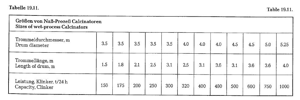
Calcinators are supplied in the following sizes (see table 19.11.).
Calcinator and Concentrator can also be applied as raw mix preheaters in the dry production process. However, before feeding into the Calcinator or Con centrator, the dry raw mix must be moistened and pregranulated, by adding about 12-14 0/o water. When used in the dry production process, Calcinator and Concentrator lower the specific heat consump tion down to about 1100-1200 kcal/kg of clinker. In the dry production process however, these preheat ers were largely replaced by raw mix suspension preheaters.
The long dry process rotary kiln
The long dry process rotary kiln was developed in the United States, since this kiln requires only little operating attendance and is not apt to upset condi tions. Originally, these 140-160 m long rotary kilns were not supplied with internal heat exchangers; this caused exit gas temperatures of about 700-750 oc. Therefore water spray was applied to reduce the temperature of the exit gases before entering the dust collector. To improve the heat economy, chain sections were then applied to the long dry process rotary kilns; also metallic cross-installations as well as ceramic heat exchangers were later applied.
Ceramic heat exchangers
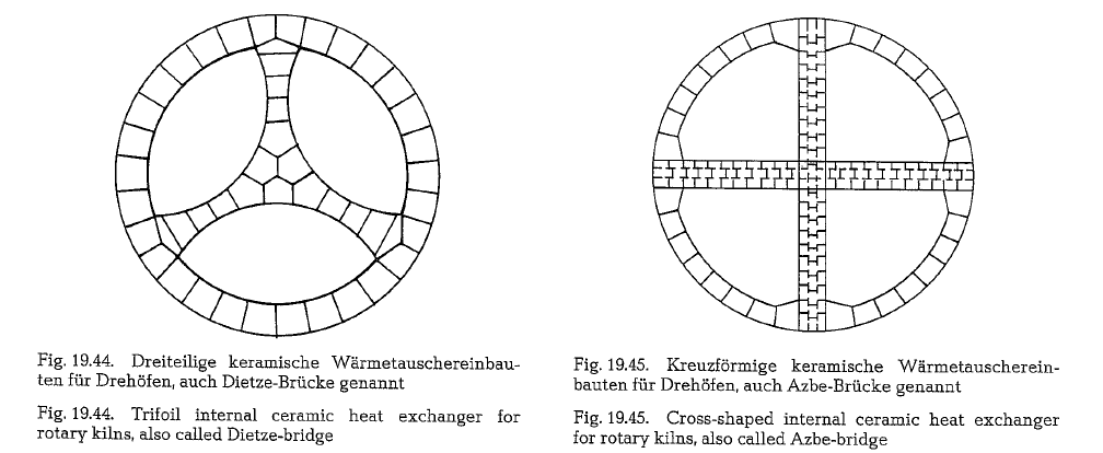
Ceramic heat exchangers (see Fig. 19.44. and 19.45.) are installed inside the kiln in about 4- 5 m long sec tions. It is a rule to install three sections with a dis tance of about 3- 4 m from each other; the particular sections are displaced by 60 o. For ceramic installa tions high refractory material with an Al203-content of 70-75 % is applied.
Fig. 19.44. shows a ceramic heat exchanger, dividing the kiln’s cross-section into three sectors. This kind of ceramic installations is called Dietze-bridge.
Fig. 19.45. shows a ceramic heat exchanger which div ides the kiln’s cross-section into four sectors or quad rants; this kind of ceramic heat exchanger is called Azbe-bridge.
The purpose of these installations is to divide the kiln feed as well as the kiln gases into three or four cur rents respectively, to create a better contact between gas und material and consequently a better heat transfer. Here, also a higher rate of heat transfer occurs between the ceramic material and the kiln feed. The thorough overturn of the kiln feed by help of the internal kiln installations makes it possible that hot material strata transfer heat to colder mater ial. Insufficient overturn of the kiln feed can cause an increase in free lime content of up to 2 % and even more, and higher loss on ignition of the clinker. The application of internal ceramic installations increases the capacity of the rotary kiln by about 8-12 %, decreasing simultaneously the specific heat con sumption at an equivalent rate. The temperature of the kiln exit gases is reduced by about 80-100 deg C. Ceramic heat exchangers are usefully installed where the temperature of the kiln gases is about 1200-1000 oc, since in this section of the kiln there is the greatest temperature difference between gas and kiln feed, and therefore this zone of the kiln is best qualified for an intensive heat exchange.
However, ceramic as well as metallic heat exchanger installations cause a higher pressure drop, which requires a higher electrical energy input for the kiln”s draft fan. In the gypsum-sulfuric acid process, where the presence of S02 in the kiln gases does not allow the use of metallic heat exchangers, ceramic heat exchangers are usefully applied.
When converting long wet process rotary kilns into dry process kilns with chain systems, in various cases an increase in clinker production by about 35- 40 % compared to wet process kilns was achieved, reduc ing simultaneously the specific heat consumption by roughly 33 %.
The exit gas temperature of long dry process rotary kilns with chain installations ranges between 380- 400 oc with these gases the raw material required for the kiln with a moisture content up to 13 % can be dried without additional heating. Using hot waste air from the grate clinker cooler as additional heating, raw material with a moisture content of up to 15 % can be dried [232b]. This is extensively utilized in Europe, where the dry process rotary kiln is usually linked to a raw material dryer, which indeed compli cates the operation. In the United States on the other hand, because of operational reasons, linking the rotary kiln to the raw material dryer is avoided. Fuel thrift was not as stringent before the current oil crises in America as in other countries.
Ceramic lifters, lifter bars
By lifting the kiln feed with the help of metallic lifter bars, ceramic lifter bricks or pocket bricks (see Fig. 19.46.), the individual feed particles are directly exposed to the gases causing an acceleration of the heat transfer. Consequently, a turbulent motion is imparted to the kiln gases thus intensifying the heat exchange.
The application of either lifter bricks or lifter bars in short dry process kilns, resulted in the following effects: Reduction of the kiln exit gas temperature from 600 to 500 °C, increase in kiln capacity by 12 %, and reduction of the specific heat consumption by 20 %. Since ceramic lifter bricks show an inclination to spalling, metallic lifter bars are better qualified for this purpose.
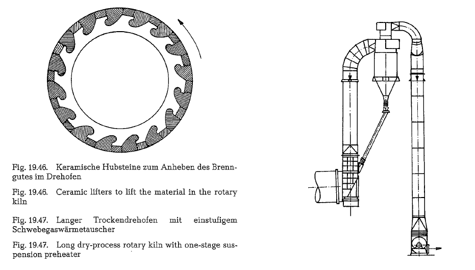
One-stage suspension preheater
To reduce the dust emission, i.e. to relieve the dust collector as well as to improve the heat economy, long dry process kilns are often combined with a one-stage raw mix suspension preheater; such a heat exchange arrangement is shown in Fig. 19.47. Usually two heat exchanger cyclones working in parallel are applied. Chapter “Raw mix suspension preheater” of this book contains more detailed information about this type of heat exchanger.
Sizes and capacities
In the Federal Republic of Germany long dry process rotary kilns amount to only 2 % of the total number of kilns. In the United States, these kilns can be fre quently seen; they consist to a great extent in the total number of dry process rotary kilns. As is well known, the dry production process amounts to 54 % in the total cement production of the United States. In the remaining part of the world, kiln manufactur ers supplied several hundred long dry process kilns to the cement industry.
Table 19.12. contains sizes and capacity data of long dry process rotary kilns.
The table demonstrates that smaller kiln units show a high clinker capacity expressed in t/m3 · 24 h. The specific kiln capacity decreases with increasing kiln size. This ratio of specific kiln capacity to the kiln size is shown in the diagram in Fig. 19.48.
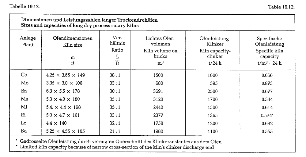
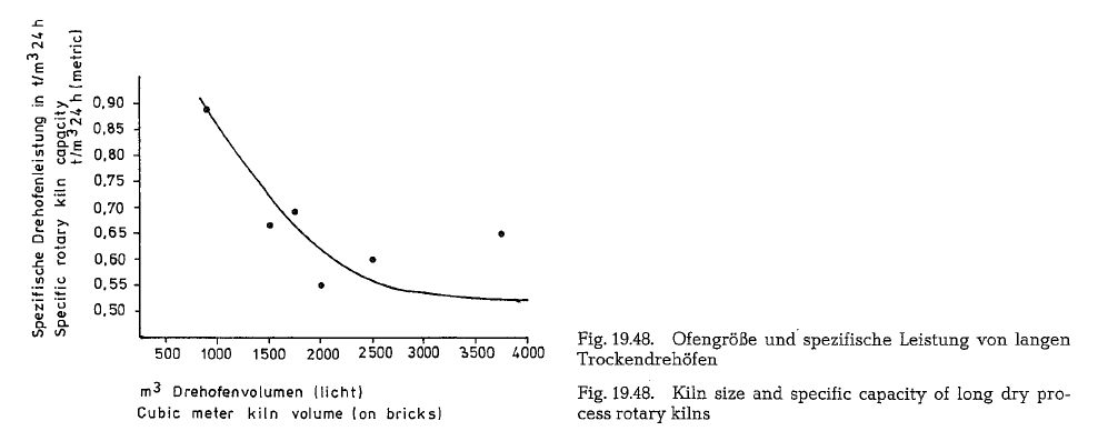
Projected sizes of long dry process rotary kilns with capacities from 3000 to 5000 t/24 h, may be as follows:
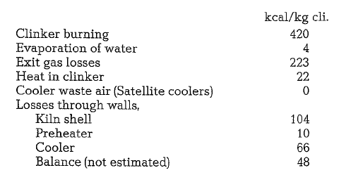
The exit gas temperature is 370 oc, and the heat con sumption amounts to 897 kcal/kg of clinker
Long dry process rotary kilns without the one-stage suspension preheater show higher exit gas temperatures of about 700-750 oc. For the dust collectors the temperature of the exit gases must be reduced to 285 oc. This is mostly achieved by employing a water spray system, which is described in section 19.7.
Cooling of the rotary kiln shell
Practical experience of the Soviet cement industry showed that water cooling of the burning zone of the rotary kiln’s shell has a protective influence on the lifetime of the refractory. Cooling of the kiln shell extends the refractory’s lifetime 1.5 to 2 times, com pared with refractory without shell cooling. Cooling of the kiln shell facilitates the formation of a protec tive coating on the refractory, especially in cases where raw mix with a high content of Si02 is employed.
Without cooling of the kiln shell, a thin fused layer of low viscosity liquid clinker phase is formed on the hot refractory, which fails to provide a protective coating. Of course, cooling of the kiln shell causes also cooling of the refractory; on the cooled refrac tory, the thin fused layer of the liquid clinker phase gets a higher viscosity, thus creating favorable condi tions for the formation of coating.
In the majority of cases where water cooling was applied, it was possible to employ in the rotary kiln’s burning zone, high alumina refractory, instead of other, more expensive kiln lining.
In rotary kilns with diameters of roughly 3.6 m and more, where chrome-magnesite bricks of 230 mm thickness were used, it was possible to reduce the thickness of the bricks down to 160 mm, and in some cases even to 120 mm, after water cooling of the kiln shell was employed. The sole reduction of the brick size resulted in savings of 20 %. Besides, a thinner lining increases the effective kiln volume and thus also the capacity of the rotary kiln.
There are no higher heat losses caused by cooling the burning zone of the kiln shell, on the contrary, it is asserted, heat losses by radiation are reduced by the insulating properties of the coating built up on the refractory.
By changing the quantity of the cooling water, it is possible to control the thickness of the coating on the refractory. In practice the cooling of the kiln shell’s burning zone is accomplished according to the drawing shown in Fig. 19.49.
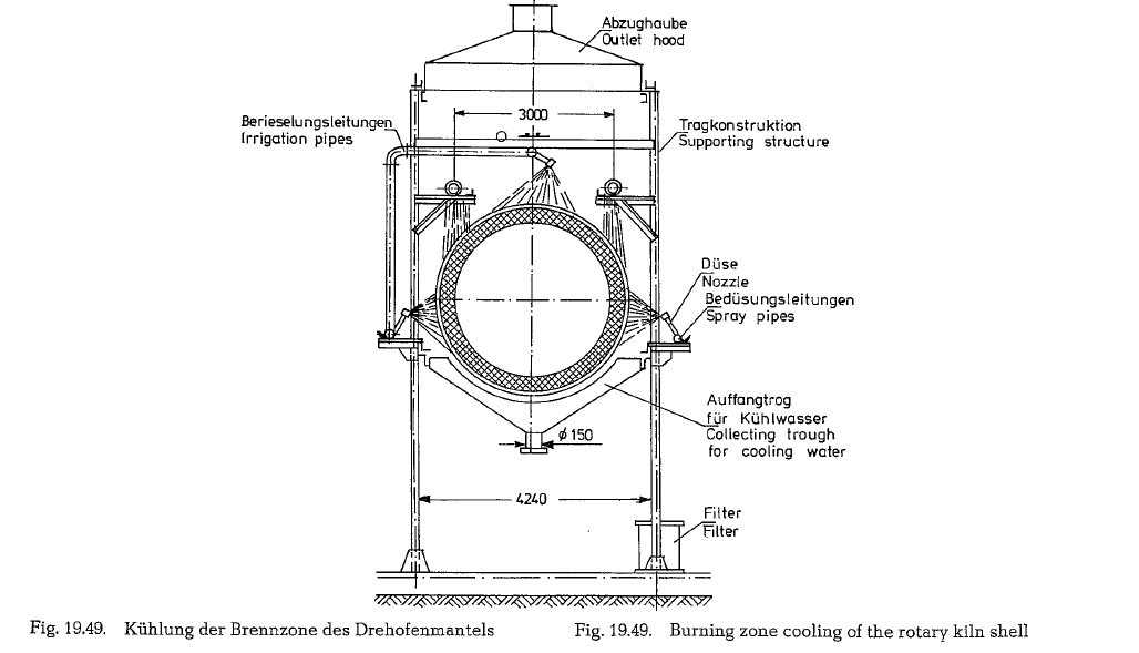
The cooling arrangement consists of two irrigation pipelines with a diameter of 150 mm; along the total length of each of these pipelines are two rows of 4 mm diameter orifices, located at a distance of 30 mm from each other. The irrigation pipeline is div ided into 8 sections with separate water supply. In order to extend the temperature curve, the irrigation orifices on both ends of the pipelines are arranged further apart. In addition to the irrigation pipelines there are also 3 water spray pipelines. After start-up of the kiln to normal operation, cooling is performed by gradually engaging the spray system to prevent sudden cooling. Later, irrigation is cut in, whereby the spray system, according to the requirements, is mostly disconnected. The spray nozzles are located in a distance of 700 mm from the kiln shell. The spray water requires filtration.
The length of the water cooled kiln section equals 6 kiln diameters, starting from the tip of the kiln burner. The water consumption for shell cooling of the 5 x 185m Soviet wet process rotary kiln amounts to 80m3/h. The cooling arrangement of the rotary kiln shell described above, is a development of the Soviet Research Institute Giprocement, and is widely employed in the cement industry of the USSR [234].
It is debatable whether cooling of the rotary kiln shell is beneficial, since there is evidence that water cooling may also have negative effects.
Cooling of the rotary kiln exit gases
Water spray is required to condition rotary kiln exit gases for passage through fabric dust collectors and to moisten kiln exit gases for electrostatic precipita tors. So-called bypass gases from suspension prehea ter kilns also require water spray. The following example shows how much water is required for the temperature reduction of kiln exit gases.
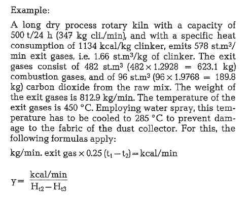
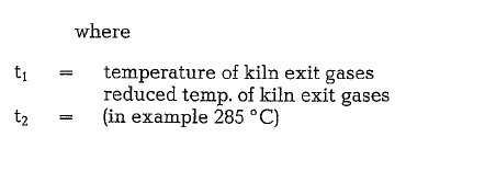
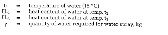
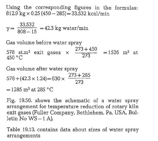
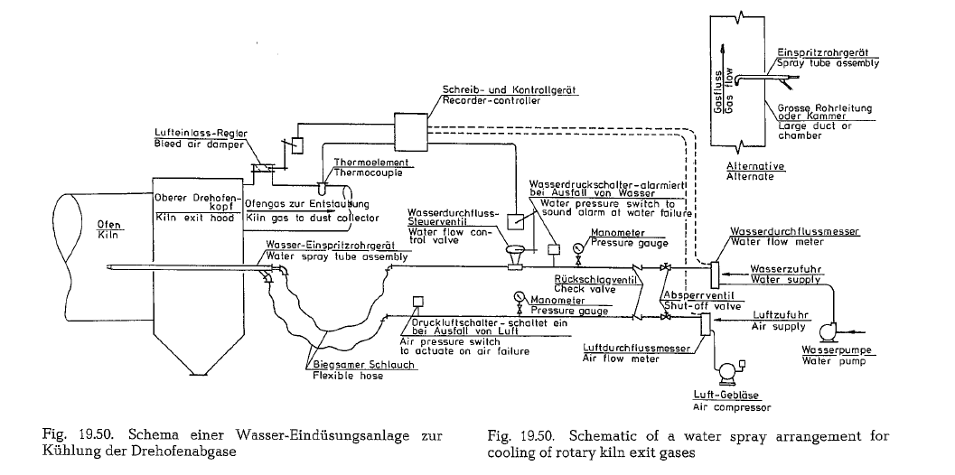
Water spray systems for kiln exit gas cooling are mostly used in the U.S., where the fuel cost was until recently not a decisive factor. In contrast to Ameri can practice, European cement plants always utilized the hot kiln exit gases for raw material drying. Utiliz ing kiln exit gases in rotary dryers or drying-grinding mills arranged behind the kiln, make water spray sys tems dispensable.
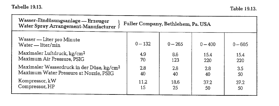
The Lepol-kiln
The invention of the Lepol kiln in 1928 was a signifi cant development in the field of the dry production process, when considered from the viewpoint of heat economy, especially under European manufacturing conditions. The term “Lepol” was created by combin ing the initial syllables of the inventor’s name (Otto Lellep) with the company’s name Polysius; the latter acquired the patent and continued the development of this process. Until World War II, the drastic reduc tion in heat consumption by more than 50%, resulted in the erection of about 120 Lepol kilns, with capaci ties up to 600 metric t/24 h, and a heat consumption of about 1000 kcal/kg clinker. After 1950, this process was further refined, resulting in the so-called double gas circuit, and 300 more Lepol kilns were erected with capacities up to 3000 metric t/24 h. Simulta neously, the heat requirement was reduced to approximately 800 kcal/kg clinker.
The main feature of this process is a short rotary kiln working in conjunction with a traveling grate; the grate is covered with a 15-20 em thick layer of raw material pellets or granules, penetrated by 1000 o C hot kiln exit gases. The temperature of the grate exit gases is about 100 oc. Due to the filtering effect of the layer of granules, the dust load of the exit gases is very low; also the low temperature as well as the con tent of water vapor make the exit gases ideally conditioned for electrostatic precipitation.
Fig. 19.51. shows the schematic of a Lepol kiln with single gas circuit. Fig. 19.52. shows the Lepol kiln with double gas circuit.
With single gas circuit according to Fig. 19.51. the rotary kiln exit gases penetrate the bed of nodules downward, from where they are withdrawn by suc tion and led to the dust collector. Fresh air is supplied through the inlet damper to the drying compartment, to prevent the bursting of the granules, due to high vapor pressure. This results in heat losses and in higher exit gas volume. Therefore, in the course of further development of this process (Fig. 19.52.), fresh
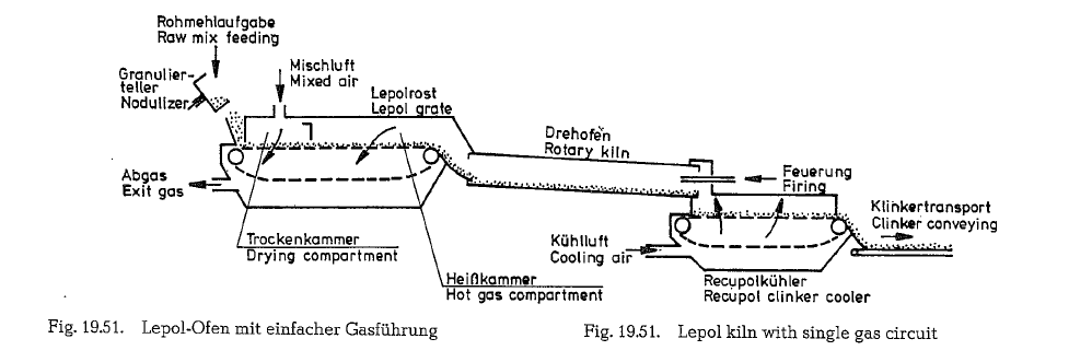
air is no longer added. With this improved process, the kiln exit gases of about 1000 o C. penetrate for the first time the bed of nodules in the 1. compartment, and after passing a set of intermediate dust collection cyclones, enter into the 2. compartment with a tem perature of about 400 ac, where they pass the bed of nodules for the second time. This results in a considerable reduction of the volume of the exit gases, which at this point show a temperature of about 100 oc.
The intermediate dust removal from the exit gases and the subsequent discarding of the alkali laden dust generated inside the alkali condensation area, creates an excellent opportunity to reduce the alkali content of the cement by eliminating this dust from circulation.
If the alkali content is to be reduced to a lower level, a bypass arrangement is closely connected to the rotary kiln inlet in the area above the traveling grate. Air is used to cool this part of the diverted exit gases, which are then led into an electric filter, to precipi tate the alkali laden dust particles. The cleaned gas is then led from the E-precipator to the drying compart ment of the Lepol grate.
Fig. 19.53. shows a flow chart of a Lepol kiln with bypass arrangement.
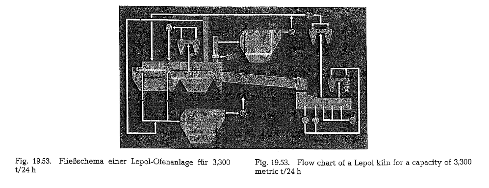
It shows a Lepol kiln with a capacity of 3,300 metric t/24 h; the wet production process is applied. This process was selected because of the high natural moisture, as well as with regard of the chlorine and alkali situation of the raw material. The chalk (22- 23 % out of pit moisture) which is quarried with a bucket excavator, is then ground together with the clay slip, screened, homogenized and stored. The slurry is then thickened with lime milk up to 40 0/o moisture. It then passes a row of eleven chamber fil ter presses, where the water content is reduced to about 21.5 %. Then the filter cake is stored in silos, whence it is withdrawn by screw conveyors, nodu lized in a kneading mill, and subsequently fed by a swinging belt conveyor to the Lepol grate; see flow chart in Fig. 19.54.
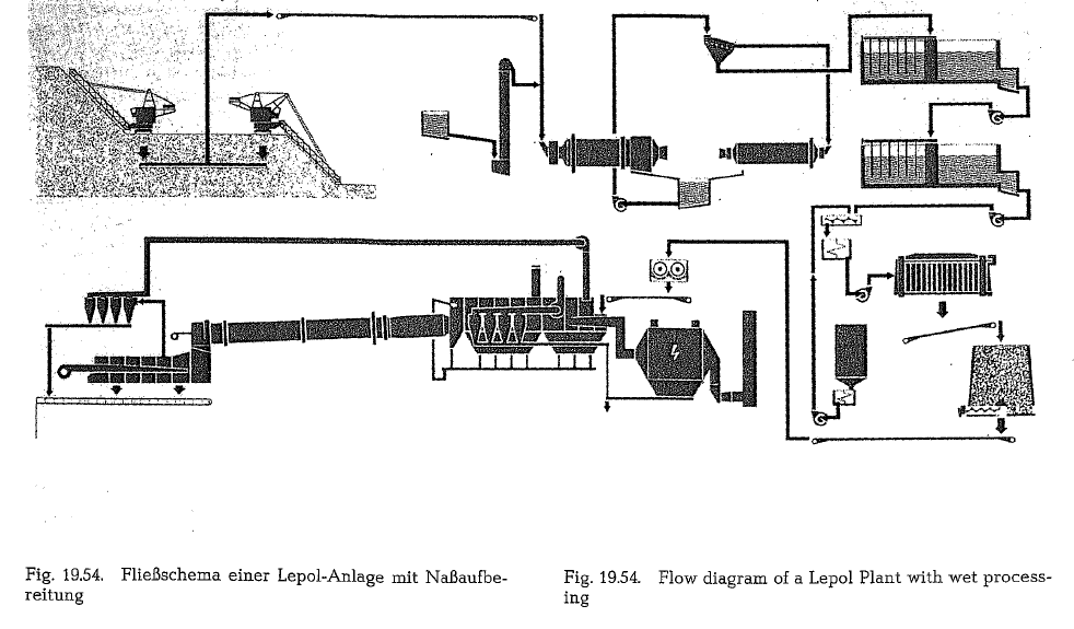
On the flow chart, Fig. 19.53., the Lepol grate is di vided into a predrying, drying, and hot gas compart ment. The gas is evacuated from the suction compart ment, and blown into the drying compartment. The predrying compartment which is supplied with clinker cooler exit air, is located in front of the drying compartment. The volume of the clinker cooler exit air is approximately 1st.m3/kg of clinker at about 290 °C.
Bypass gas is drawn off from the hot gas compart ment; it is then mixed with air which results in cooling to a temperature of 420 oc, cleaned in an electricprecipitator and also led into the predrying compartment.
The resulting advantages are:
- No expensive dust removal from the clinker cooler exit air.
- No additional dust source generated by the clinker cooler.
- Low heat losses by the cooler exit air and the bypass gas.
The sizes of the machinery are:
Lepol grate 5.6 x 61.7 m
Rotary kiln 5.6 x 90 m
Clinker cooler 3.3 x 31.3 m
In addition to the Lepol kiln with double gas circuit, raw mix suspension preheaters were developed, which are described in the following chapters of the book.
Despite the enormous expansion of the raw mix sus pension preheater kilns, the Lepol kiln remained pre dominant in cases with special raw material condi tions, such as, e.g. high alkali content, or where raw material properties exclude the preparation of dry raw mix. The Lepol kiln”s advantage is its versatility, since this kiln is also used for burning of crushed rock such as limestone or dolomite gravel and the pyroprocessing of nickel and iron ore pellets [234a, 234b].
Pingback: Cement Rotary Kiln Design | Key Factors in Rotary Kiln Shell Design