Contents
Fuels in the cement industry
In the physical state, fuels may be classified as solid, liquid, or gaseous. All three are employed in the cement industry. The solid fuels are: coal (anthracite), lignite, peat, wood, and coke. Coal and lignite are used in cement rotary kilns and in dryers. Coke is used in cement shaft kilns. Among liquid fuels it is heavy fuel oil which is predominantly used in cement manufacturing. Natural gas is the most common gas eous fuel in use. The use of other gases is of minor importance.
TO DOWNLOAD THE EXCEL SHEET AND ALL THE OTHER USEFUL BOOKS AND RESOURCES KINDLY CLICK HERE


In the 1890″s pulverized coal firing was achieving its first real commercial success in the cement industry of the United States. Thomas A. Edison, in the early 1900’s made improvements in the firing of pulverized coal in cement kilns, greatly increasing their effi ciency and output. Pulverized coal firing has largely developed as an empirical art. Theoretical under standing has generally followed rather than preceded practical accomplishments in the field of pulverized coal firing.
The investment costs of coal mines are roughly 20 times higher than that of oil or gas wells. Again, the exploitation cost of natural gas is 3- 5 times lower than that of crude oil. The shipment of natural gas does not require elaborate transportation, and the construction costs of gas pipe lines are only a fraction of the construction costs of railroads for transporta tion of coal. Generally, the investment cost of gas pipe lines amortize within 3- 5 years. On the other hand, with gas pipe lines, the cement industry depends only on one supplier.
The cost of a coal preparation department of a cement plant amounts to about 15-20 % of the cost of the total plant machinery. In comparison, natural gas is especially advantageous since no machinery is required for its preparation and storage.
The preparation of 1 t of coal and grinding to 8-10% residue on the 170 mesh sieve is connected with the following energy requirements:

Depending on the heating value of the coal, a clinker: coal ratio of 4:1 can be assumed.

When switching from coal to natural gas in existing cement plants, it was repeatedly possible to lower the cement production cost by 8-10 %. Simultaneously, the production of cement per plant worker increases by about 6-8 %.
Table 18.1. contains the proportions of the three kinds of fuel used in the manufacturing of cement in the United States.

Since the combustion of natural gas and fuel oil is practically ash-free, it is simpler to make a proper raw mix. Thus the chemical composition of the raw mix is free of variations which might occur due to dif ferent ash contents of the coal. This advantage is also applicable with the use of natural gas.
Table 18.2. contains data concerning the consumption of the three kinds of fuel for the production of cement in the United States, arranged according to the wet and dry production process.

In 1981 the production of cement in the Soviet Union amounted to roughly 127 million t (metric) [142b]. Since a considerable amount of blended cements are produced in the Soviet Union, it is difficult to deter mine the rate of clinker production. Soviet Cement Standards permit the use of large amounts of hydraulic additives to various types of cements. Therefore, in this way much fuel can be saved for clinker burning. A Soviet official source quotes sav ings of 40 % of fuel by using hydraulic additives [142c]. From this it can be speculatively assumed that disregarding the addition of gypsum -the above quoted figure of produced cement, contains only 60 % of clinker. In the 60s, about 60 % of the produced clinker were burnt with natural gas. Approxi mately equal parts of the remaining clinker were burnt with fuel oil or coal.
After a production of 33 million t (metric) in 1980, the cement production in the Federal Republic of Ger many dropped to 27.5 million tin 1982. Also a contin ued conversion of the German cement plants from oil to coal can be noticed. In the past 10 years, depend ence on oil has been reduced from 80 to 8 0/o. The consumption of natural gas is no longer mentioned in the statistics
Coal used in the cement industry should comply with the following requirements:
LHV 6500- 7000 kcal/kg
Ash: 12-15%
Volatile matter: 18-22 0/o Moisture up to 12 0/o, as delivered.

In some East European countries brown coal for clinker burning is frequently employed.
This coal has the following properties: LHV = 4800 kcal/kg
Ash: 12 0/o
Volatile matter: 40- 50 %
Fineness: 40 % residue on the 170 mesh sieve.
In the German Democratic Republic, mixed firing is successfully applied. The composition is as follows: 50- 75 % lignite and 50- 25 % bituminous coal.
Lepol kilns are fired with the following mix: 40 % lig nite and 60 % bituminous coal.
The cement industry of the USSR uses coal from nearby coal mines. Often, this coal is of inferior quality, e. g. dust coal and coal mud. Table 18.3. con tains information about properties of coal used in the cited cement plants.
Solid fuels- Coal
Solid fuels consist of organic and mineral consti tuents. The organic constituents include carbon (C), hydrogen (H), oxygen (0), and nitrogen (N). Sulfur (S) and ash comprise the mineral composition. Coal ash may quantitatively consist of: 15-21 % Al203, 25- 40% Si02, 20-45% Fe203, 1-5% CaO, 0.5-1% MgO and 2- 8 % S03. Some coals show a content of chlorides which generally is in the range from 0.01 to 0.1 %; coals high in ash contain chlorides up to 0.4 %, and fluorides up to 0.02 %.
Brown coal ash consists of 25-40% CaO, 3-10% Al203, 0.5-5 % MgO and up to 40 % S03. Besides mineral constituents, coal ash contains salts (chlor ides and sulfates), and volatile matter such as water of crystallization in clay minerals. It also contains ar bon dioxide in the carbonates and sulfurous acid in the sulfates.
Table 18.4. contains the elementary composition of coal and coke.

The combustible components are carbon, hydrogen, and sulfur; when burning, these constituents combine with oxygen from air and generate heat. The higher the portion of combustibles in the fuel, the higher is its heating value. When evaluating fuel, only the content of carbon and hydrogen is rated. Sulfur, although combustible, is not desired, since its combustion prod uct is sulfur dioxide (S02), which in combination with water forms sulfurous acid (H2S03); sulfurous acid causes corrosion of the metallic parts of the kiln and behaves as exit gas in the atmosphere very destruc tive to the organic environment. Sulfur which remains in the coal ash becomes part of the clinker during the burning process, thus lessening its quality. Additionally, it should be noted that in certain cases a minimal amount of sulfur is even desired, since this sulfur causes sulfatizing of the alkali oxides. These alkali sulfates generated in this way, are the most stable sulfur containing phases, and leave the kiln with the clinker, thus reducing the alkali circulation in the kiln system. Only excessive sulfur results in obnox ious S02-emissions from the cement kiln [249]. Ash and moisture are undesirable constituents of fuels, and are designated as inert contents. During the burning process, the ash is almost completely absorbed by the clinker; therefore the chemistry of the coal ash must be taken into consideration when calculating the chemical composition of the raw mix.
When drying coal it should be noted that completely dry coal is difficult to ignite. As is known, carbon does not react directly with atmospheric oxygen; the combustion to CO and C02 proceeds by way of chain reactions where carbon reacts first with the more active OR-radicaL The presence of small quantities of water vapor is required for the ignition of fueL Thus, the drying process of coal should not go too far. A moisture content of approximately 1- 1.5 % in the pulverized coal promotes combustion.
Volatile matter
The content of volatile matter is important for the rating of coals. The loss in weight as the result of carbonization of coal under exclusion of air, represents the total of volatile matter.
Coal from younger geological formations contain more parts of oxygen, hydrogen, and nitrogen than coals from older geological formations. During combustion, these elements and their compounds generate more volatile matter than coals from older geological formations.
When burning coal on the fire grate, the length of the flame depends on the content of volatile matter. Coals which are high in volatile matter, generate a long flame on the fire grate and are called long-flam ing coals, whereas coals containing little volatile mat ter produce short flames and are therefore designated as short-flaming coals.
However, coals behave differently by burning them as pulverized coal in rotary kilns. Long-flaming coals injected as pulverized coal into the hot rotary kiln, decompose with high speed. The gasified volatile matter burns off immediately and the segregated coke particles are highly porous; this allows for a quick and complete access of oxygen, thus enabling a fast combustion of the coke. These circumstances promote fast combustion limited to a short section of the rotary kiln, thus generating a short flame.
Short-flaming coals contain little volatile matter, and decompose only slowly when burning in the rotary kiln as pulverized coal flame. The low content of vola tile matter causes slow combustion along an extended kiln section, and the more dense coke has a low combustion velocity. As a result, the so-called short-flaming coal, when burned as pulverized coal in a rotary kiln, generates a long flame.
The standard content of volatile matter for coals used in the combustion of pulverized coal is about 18- 22 %. However, when applying proper grinding, it is now possible to utilize also low gaseous coals in rotary kilns.
Coal analysis
Two kinds of analyses are in use for the classification of coal:
- The proximate analysis; this analysis involves quantitative determination of moisture, volatile matter, carbon and This analysis is for quick preliminary appraisal of coal.
- The ultimate analysis; this analysis is for the exact calculation of combustion processes, and involves quantitative determination of the following con stituents: moisture, carbon, hydrogen, sulfur, oxy gen, nitrogen, and ash.
Heating value
The most important property of fuels is the heating value, i. e. the quantity of heat generated from 1 kg (or 1 m3) of fuel during combustion in the furnace. The heating value is exclusively determined calorimetri cally. Calculation of the heating value derived from the ultimate analysis is only for preliminary informa tion.
The lower heating value which is standard in Euro pean practice, takes into account the heat losses spent for the evaporation of fuel moisture as well as of the water generated from the combustion of hydro gen. This heat could be regained as a result of water vapor condensation, i. e. in the process of cooling the combustion gases. However, since the temperature of the kiln exit gases is over 100 °C, the heat of vapori zation (539 kcal/kg of water) cannot be utilized for kiln operation. With no moisture and hydrogen in the fuel. the lower heating value equals the higher heat ing value. The following formula should be applied when converting the higher heating value into the lower heating value:

Heating value and heat consumption
To insure economic kiln operation, the heating value of the coal should be about 7000 kcal/kg. Coal with lower heating value increases the specific heat con sumption for clinker burning, decreasing simulta neously the specific kiln throughput. Fig. 18.1. con tains a diagram, showing the ratio between the spe cific heat consumption and the heating value of the coal when burning clinker in the rotary kiln.

Thermochemical reactions and gas volumes


Ignition temperature of coal
Ignition temperature ist that surface temperature of a fuel at which the combustion reaction reaches a speed which insures the uninterrupted burning of fuel. To reach the ignition temperature, a certain period of time -the ignition time -is required. The ignition time is that time which is needed to raise the temperature of the fuel surface to ignition tempera ture. This time is determined by the temperature gra dient and by the heat transfer conditions. It results from the fact that the surface is a determining factor of the ignition; also, the surface of the fuel depends on the particle size, i. e. on the fineness of grinding (in the case of coal.) Thus it is possible to regulate the ignition temperature and the ignition time by con trolling the fineness of the ground coal. The curve in Fig. 18.2. shows the relationship between the ignition temperature and the fineness of the coal. The upper limits refer to anthracite, and the lower limits to high volatile coals, i.e. coals with high volatile matter
The diagram shows that the ignition temperature of pulverized coal is between 200 and 550 oc. It is further evident that the fineness has a more important influence on the ignition of coal than the content of volatile matter.
Pulverized coal and combustion air must be heated to ignition temperature. At 20 % excess air, the heating of the combustion air requires about 90 %, whereas the heating of the pulverized coal requires only 10% of the heat, which is necessary for ignition.

Burning time
The faster the combustion gases are removed and replaced by fresh air, the faster the coal particles burn. To fulfill this precondition, a high relative velocity between combustion air and the coal parti cles is required. The combustion process consists of two phases: the removal of volatile matter, and the combustion of the solid constituents, i. e. the coke. Gumz [172] developed a combustion time formula, which was used for the derivation of a combustion time diagram for coal dust particles. The diagram indicates the combustion time in seconds, for coal dust particles with diameters from 0.02-0.5 mm, at combustion temperatures of 900 and 1500 °C; see Fig. 18.3.

Heat transfer from the coal dust flame
Fuel gases or flame gases respectively, pass their heat to the environment mainly by radiation and only to a small degree by direct contact with the material to be burned, i. e. by convection.
Only about 13 % of the rotary kiln volume is usually filled, therefore the major portion of the heat is trans ferred to the kiln lining with the kiln feed receiving a relatively small portion of the total heat volume.
The largest portion of the heat transfer occurs by radiation. The rules of radiation of solids cannot be applied to radiation of flames. The flame radiation does not occupy the total thermal spectrum. Monatomic and diatomic gases such as nitrogen and oxy gen are in the range of infra-red, entirely transparent, and their thermal radiation equals zero. Therefore, the presence of these gases in the flame is only a bal last. On the other hand, gases with a higher number of atoms, such as e. g. H20, C02 and S02, develop a considerable thermal radiation, due to their absorption bands in the infra-red range. C02, e. g. radiates in the range of the following absorption bands in milli micron (10-9 meter); A = 2.64-2.84, 4.13-4.47, and 13.0-17.0.
Water vapor has five absorption spectra with the fol lowing maximum wave lengths A: 1.36, 1.85, 2.70, 5.90 and 19.60. The dependence of the gas radiation on the temperature is different than that of solid bodies. The exponent for C02 is T3,s, and for water vapor T3, instead of T4, resulting from Stefan-Boltzmann’s law.
Thus the radiation active constituents of the pulver ized coal flamme are:
- The C02-content of the flame gases
- The H20-content of the flame gases
- The content of suspended dust in the flame
Schack [173] developed formulas to calculate the heat radiated by C02 and H20. The following require ments result from these formulas to promote the heat transfer by the gases in the clinkering zone:
- An increase in the flame temperature
- An increase in the concentration of C02 and H20
- An increase in the kiln diameter, up to maximum limits.
Combustion gases
The diagram shown in Fig. 18.4. indicates the volume of combustion gases in m3, which is generated when burning 1 kg coal with heating values from 5000 to 9000 kcal/kg with the application of 10 % excess air. The diagram is based on analyses of roughly 30 American kinds of coal.
Flame temperature
For the calculation of the coal flame temperature, the same formula as for the calculation of the fuel oil flame temperature can be applied; see section 18.2. Fuel oil.

Nitrogen oxides include nitric oxide, NO; nitrogen dioxide, N02, and dinitrogen oxide, N20. They are produced, among others in the combustion flame of the rotary kiln, and enter the atmosphere with the exit gases. Oxides of nitrogen undergo many reac tions in the atmosphere. Nitric oxide reacts with oxy gen to form nitrogen dioxide. The presence of NO and N02 results in the following reaction:

Nitrogen oxides with the exception of N20 (laughing gas) are poisonous; so e. g. nitrogen dioxide can be harmful when inhaled, and nitric acid can be prod uced on the lung tissue with the moisture in the lungs*; it also·can combine with the hemoglobin of the blood, diminishing its oxygen carrying capability.
Since during the combustion process in the rotary kiln various oxides of nitrogen are generated, these oxides are frequently designated with the collective formula NOx. NO, i. e. nitric oxide or nitric monoxide, is generated in the flame, in connection with which two kinds of NOx are distinguished. If the NOx is par tially generated by the reaction of the oxygen with the nitrogen of the combustion air then we have to do with the so-called thermal NOx. If the NOx formation results from oxidation of the fuel’s nitrogen com pounds, then the product is the so-called fuel-NOx. Nitrogen dioxide, N02, results fom the reaction of the already existing NO with the oxygen of the combus tion air.
Many fuels contain organically combined nitrogen. If the total amount of this nitrogen would be trans formed into NOx, then the concentration would be very high. However, in a cement rotary kiln no con nection between combined nitrogen and NOx was noticed.
Furthermore, the oxygen concentration in the flame as well as the kind and velocity of mixing of oxygen with the fuel, are of great importance for the temper ature and the NO-formation. The mixture depends to a large degree on the kind of fuel, and on the content of volatile matters.
An increase of the material temperature in the combustion zone causes an increase in the formation of NOx. A very hot combustion zone can result in a strong increase of the NOx content. Also, a shorter and sharper flame can cause an increase in NOx-formation:
It is said that with the aid of an NOx-recorder, the kiln operator is in the position to control the kiln in such a way that he can reduce variations in the NOx content of the kiln gases, thus securing a greater kiln operating stability. Above all kiln coating in the burn ing zone can be avoided. Likewise, an increase in the content of free lime as well as an increase in the liter-weight of the clinker are depending on the NOx-content of the combustion gases [173 b]. Further more, a paper reports about the determination of nitrogen oxides in the combustion gases [173 c]. Ono, Katsuki et al. report about a catalytic reaction of nitrogen oxides with carbon monoxide over cement raw mix to reduce the content of NOx of the rotary kiln exit gases in the preheater, whereby iron com pounds are the active catalysts.
A recent U.S. survey revealed that the cement indus try contributes only 0.4 % to a total annual NOx emis sion of more than 22 million tons, and is thus among the minor offenders. The following tabulation shows the sources of NOx producers in the United States.
For the environmentalists however, it seems to be easier to control 148 cement plants than 125 million motor vehicles which emit NOx gases unpunished. In the United States, the regulations are not uniformly. There exist few Federal regulations, and a number of state and local ones. Some of these take into account the ambient air quality at the place of reception (0.05 ppm), some limit the NOx concentration in relation to the type and size of the particular cement plant, while others put a limit on the hourly exhaust.

Equipment for determining NOx is a du Pont Spectro photometric Analyzer, Model 411, designed for con tinuous monitoring of S02, and discontinuous NOx analysis. An FLS modification of this instrument mea sures NOx automatically every 10 minutes.
Coal preparation
Pulverization of coal requires special precautions for preventing coal dust explosions. A coal dust explo sion occurs if the following three conditions exist:
- The concentration of coal dust in the gas mixture is within the explosion limits.
- The oxygen content in the gas mixture is suffi cient for an
- There is sufficient thermal energy to cause an
Thus the absence of one of these three factors would be theoretically enough to prevent a coal dust explo sion. In practice, however, it is preferable to eliminate two or, possibly, all three factors.
However, as this cannot always be guaranteed, special design features are provided for coal grinding plants (inert operation, explosion-resistant construc tion, etc.)
Concentration of coal dust
For mineral coal, the range of explosion is within con centration limits of 150 grams/stan. m3 (lower explosion limit), up to approximately 1500 grams of coal dust (upper explosion limit) per stan. m3 of air. These concentration limits may vary, depending upon the gas content and the fineness of the coal. The fineness of the coal dust should be equivalent to a residue of 10-15 % on the 170 mesh sieve (sieve opening 88 microns). The concentration range below the lower explosion limit is between 0-150 grams/stan. m3, and is rather narrow. In the pulverization of coal, this range of concentration cannot be considered because of excessive gas requirements.
One would also rather avoid working with coal dust concentration within the explosion limits, i. e. between 150 and 1500 grams/stan. m3, even in the absence of the two other factors. The coal dust con centration which lies above the upper explosion limit is the only effective concentration which can be prac tically utilized in coal drying-grinding plants.
Oxygen in the gas mixture
There should be a maximum of 14% oxygen in the drying-grinding system. Part of the exit gases is recir culated to reduce the 02-content.
As to the 02-content, dangerous situations might sometimes originate during plant start-up operations. Lowering the 02-content results in increase of the lower explosion limit and decreases the upper explo sion limit, thus narrowing the explosion range. This provision also increases the ignition temperature of the gas mixture.
Sufficient thermal energy
The thermal energy required for causing an explo sion can originate from the following three sources:
- Self ignition of coal.
- Overheating of the coal by excessive hot drying gases.
- Overheating of machine parts.
Coal drying
Drying of coal with moisture contents in the range from 15-40% is mostly performed in drum dryers, the same type of dryers employed for raw material drying. The temperature of the flue gases entering the drum dryer should not exceed 450 °C; this results in a higher specific heat consumption for coal drying compared to drying of cement raw material.
The temperature of the drum dryer’s exit gases should be approximately 120 oc, and that of the dried coal, approximately 70 o C.
The rate of evaporation for coal drying in drum dryers is 25-35 kg of water vapor per 1 m3 of dryer volume per hour. Waste heat from rotary kilns and from clinker coolers is used to operate drum dryers for coal drying; frequently, hot air from the kiln hood is employed.
The heat consumption for coal drying in drum dryers is approximately 1500 kcal/kg of water.
Coal should be dried to a residual moisture content of 1-1.5%.
The maximum moisture content of coal to be dried in drying-grinding plants is 15 %. The maximum tem perature of the hot gases entering the drying-grind ing plant should be 350 °C.
Coal grinding
Coal grinding is performed either in bowl mills or in tube mills [171c]. The fineness of the ground coal should be equivalent to a residue of 1.5-2 % on the No. 70 mesh sieve and of approximately 15% residue on the No. 170 mesh sieve. The rule is approximately:
The shorter the rotary kiln in which the coal is burned, the finer the coal.
The energy consumption for grinding of coal is within the range of 10-30 kwh/t.
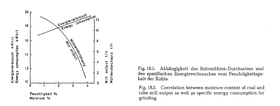
The moisture of coal has a significant influence on the capacity of the mill. For a moisture increase from 1-3 % the capacity of a tube mill decreases by about 45 -50 %, with a proportionate increase in specific energy consumption of about 10 % for the same parti cle size; this correlation is diagramatically shown in Fig. 18.5.
It should be mentioned that the shown capacity decrease when grinding coal with increasing mois ture applies only to grinding plants which are not supplied with a sufficient volume of hot gases.
Therefore, as already mentioned, coal should be dried to a residual moisture content of 1-1.5 %.


Mode of operation of coal mills
As to the compatibility of the coal mill and the rotary kiln, there exist basically two different modes of operation:
The direct firing mill
This mill functions directly with the rotary kiln and must adjust to the demands of the kiln.
The investment cost of a direct firing mill is roughly 40 % lower than that of a comparable installation with bin firing.
However, under certain circumstances, the opera tional dependence of the kiln upon the direct firing mill results in a bottleneck.
Control of the rotary kiln flame is complicated by the direct coal firing mill. Water vapor from the coal is blown into the rotary kiln along with the dried coal, thus reducing the flame temperature. It is said that each per cent of coal moisture lowers the flame temperature by 10-14 deg C. thus decreasing the throughput of the kiln. It is known from experience that an increase of the flame temperature by 10 deg C causes an increase in kiln production by at least 1 0/o.

Fig. 18.6. shows a flow diagram of a direct coal firing mill
Fig. 18.7. shows a similar arrangement, but with an air-swept mill (ball mill); the drying heat is drawn from the hot kiln end of a rotary kiln, equipped with satellite coolers. Otherwise, this mill shows all draw backs of a direct firing mill, as described above.
The drawbacks of a direct coal firing mill are elimi nated in the drying-grinding arrangement shown in Fig. 18.8. A feed hopper with a few hours’ storage capacity, positioned on load cells, is located between the cyclone collector (6) and the primary air fan (8). The load cells control the mill feed. The coal dust is sup plied into the kiln by a feeding screw conveyor. The mill exit air is blown into the kiln as primary air.


The central grinding plant or bin firing system
The mill capacity of a central grinding plant is essen tially higher than the coal consumption of the kiln. This creates a stockpile of coal dust, which functions as a surge between kiln and mill. The central grinding plant is generelly necessary where several kilns or several firing units of one kiln system are to be sup plied with fuel from the same grinding plant.
Fig. 18.9. shows the schematic arrangement of a central coal grinding plant.
Fig. 18.10. shows a similar arrangement (central grind ing plant) employing Tirax-type ball mills (F. L. Smidth). Also here, the drying heat is drawn from the hot kiln end.
The mills shown in Fig. 18.8. to 18.10. are ball mills with large intake openings (air-swept mills), for drying-grinding of raw coal with an initial moisture content of up to 20 %.
These mills are supplied with one dyring and two grinding compartments, working in closed circuit with a separator. For a large air inflow into the mill, the feed end is provided with an appropriate opening; therefore, this side of the mill rests on a slide shoe bearing, whereas the discharge end is positioned on a trunnion bearing (see Fig. 18.11.).


The F. L. Smidth Co. developed a standard series of coal drying-grinding mills, with a capacity of 4-30 metric t/h of dry coal (see table 18.7.). The mill capa city is based on coal of normal grindability and closed circuit grinding with air separator. The particle size of the mill feed should not exceed 15 mm, at a moisture of maximum 10 %. The product is ground to a fine ness of 85-88 % passing the No. 170 ASTM-sieve.

Liquid fuels- Fuel oil
The most important property of fuel oil is its ability to burn in the liquid state. Paraffins, olefins, napthenes and aromatic compounds are the four main groups of hydrocarbons forming fuel oils. The most significant fuel oils are:
Mineral fuel oil (from crude oil)
Coal-tar oil (from low-temp. carbonization of coal)
Bituminous coal-tar oil (from low-temp. carbonization of bituminous coal).
Fuel oils consist of several hundred compounds of hydrocarbons. Generally, fuel oils consist of 85- 90 % carbon, 5-10% hydrogen; oxygen, nitrogen, and sul fur amount to about 3-4 %. In some kinds of fuel oil, the sulfur content amounts up to 3 %. Despite large variations in viscosity the heating values are within the limits of LHV = 8500-10,000 kcal/kg.
Viscosity
The most significant characteristic distinguishing fuel oils is their viscosity. Viscosity is a scale for internal friction and depends on the temperature of the oil.
Viscosity is measured in absolute and empirical units. In continental Europe the Engler scale is employed, whereas in England the viscosity is measured in Red wood-seconds and in the USA in Saybolt-seconds (Universal and Furol). In the absolute system of units, viscosity is indicated in Poise as dynamic viscosity,


and in Stokes as kinematic viscosity. Thus e. g. 1 cen tistokes equals the viscosity of water at 15 a C. Engler-degrees indicate the ratio of the discharge time of oil to water; fuel oil of 100 Engler-degrees (E) requires a discharge time which is 100 times longer than that of water. Engler-degrees are not propor tional, that means 10 Engler-degrees do not have dou ble the viscosity of 5 Engler-degrees; on the other hand the double amount of centistokes equals the double viscosity.
High viscosity fuel oils are considerably cheaper, but require preparation and preheating facilities to lower their viscosity. Despite these additional expenditures their thermal price is lower than that of light-weight fuel oils.
Table 18.8. contains a comparison of different viscos ity scales.
Viscosity reference temperatures are: For Redwood 37.4 °C, for Saybolt 21 oc, for heavy fuel oil (No 6 oil according to ASTM) Saybolt-Furol 50 oc and Say bolt-Universal99 oc.
With rising temperature the viscosity of fuel oils decreases, becoming nearly constant at 120 oc. For this reason it would be useless to heat the oil beyond 120 octo lower its viscosity, with the aim of achiev ing better atomization in the burner.
Specific gravity
The specific gravity of fuel oils is generally around 1 g/cm3 at 15 oc. Specific gravity measured at other temperatures should be converted to 15 oc, applying the cubical expansion coefficient of 0.00065/degree C.
In the United States the specific gravity is expressed as Sp. Gr. 60 °F/60 °F. This is the ratio between any volume of oil at 60 oF (15 °C) and the weight of an equal volume of water.
The US-oil industry measures the specific gravity of oil in API-degrees (American Petroleum Institute). To convert the API-scale to specific gravity at 15 oc (Sp. Gr. 60/60 F), the following formula is used:

The German designation density (Dichte) is in this matter not used in America, where the specific grav ity is applied. Referred to water at 39.2 oF (4 o C), the specific gravity equals numerically the density.
Table 18.9. contains a classification of American fuel oils with data concerning specific gravity and heating value.
According to this table, American fuel oils are div ided into 5 classes (fuel oil No 3 is eliminated). The cement industry uses mostly fuel oil No 6.
Table 18.10. contains typical analyses and properties of US-fuel oils.
Fuel Oil specified commercially as Bunker C-Oil, cor responds roughly to No.6 fuel oil.
It should be noticed that American standards for fuel oils (Tentative Specifications for Fuel Oils, ASTM, Des. 396- 64 T), do not contain regulations pertaining to the maximum sulfur content.

German specifications DIN 51603 (1976) contain requirements for commercial fuel oils in West Ger many. Four kinds of fuel oils are specified:
- Fuel oil EL, super light
- Fuel oil L, light
- Fuel oil M, medium
- Fuel oil S, heavy
Fuel oils L and M are products from anthracite and bituminous coals; fuel oils EL and S are crude oil products. Fuel oil S is commonly used in cement rotary kilns, and depending on local resources, also fuel oils L and M. Proper atomization in the oil burner, requires preheating of fuel oil S to 120 ac whereas fuel oils L and M require preheating only to 80 °C.
Table 18.11. contains data for fuel oil S, which is mainly employed by the German cement industry; data are from Standard Specification DIN 51603.
Heating value
In countries using the metric system, the heating value of fuel oils is expressed in kcal/kg as LHV. In America, the heating value is quoted in either Btu per gallon at 60 op or Btu per pound. The heating value per gallon increases with the specific gravity. The HHV of No 6 fuel oil is about 150,000 Btu/gallon. The heating value per pound varies with the specific gravity. With decreasing specific gravity the heating value increases, since the lighter oil contains more hydrogen. The HHV per pound is roughly 18,000 Btu. The heating value of heavy fuel oils varies only slightly.


Because of the heat of formation during combusion, Dulong’s or other similar formulas are not applicable to calculate the heating value of fuel oils. The heat of formation represents the energy necessary to disso ciate the fuel’s molecules into reactive individual ele ments. Thus the heat of formation is the difference between the total of the heat of combustion of the particular elements and the heat of combustion of their compounds in the fuel.
The heating value is determined as HHV in the bomb calorimeter. To convert the HHV into LHV, the fol lowing formula is used:


To remove vanadium, sulfur and other harmful com ponents, additives are employed, which form emul sions with these components; these emulsions are easy to separate. In Germany, Vescolin and Vanafag in a ratio of 1 : 1000 are added to the fuel oil for this purpose.
Flame temperature
The theoretical flame temperature from the combus tion of fuel oil can be derived from the following for mula:

Fig. 18.12. shows a diagram where the theoretical flame temperatures of fuel are plotted versus the rate of excess air and the temperature of the secondary air. The heating value of the fuel oil is LHV = 9,765 kcal/kg, and the specific gravity is 0.96 g/cm3 (15.9° API), at a sulfur content of 2 %
Preparation of fuel oil
The fuel oil which is delivered to the cement plant by a variety of methods of transportation, is conveyed by a set of discharge pumps to the storage tank. If neces sary, the discharge terminal is also equipped with a heating arrangement for heating the fuel oil in the tank cars to accelerate the outflow of the oil. The cap acity of an oil tank in a cement plant depends on the fuel oil consumption as well as on regional transpor tation conditions. Storage tanks with capacities of 1000 to 10,000 m3 of volume or more are in use. Lon ger distances between the oil storage tank and the rotary kiln necessitate an intermediate tank. The vol ume of this tank usually equals one day”s oil consumption
To be both pumpable and prepared for atomization in the kiln burner pipe, the fuel oil must have a proper viscosity, as has previously been described.
To heat the fuel oil, generally three different media are used: water vapor, heat carrier liquid, and electri cal current. It would not be economical to heat the whole content of large fuel oil storage tanks to keep the oil in a pumpable state. It is sufficient to heat the oil locally, close to the discharge pipe; this is per formed by the application of so-called suction-hea ters, as shown in Fig. 18.13.

Large storage tanks are supplied with up to four suc tion heaters with a heating power of approximately 75 kW each. To make the fuel oil pumpable, it is heated to about 30- 50 o C. This is also the entering temperature of the fuel oil into the pump and heater set.
Since steam is not always available in cement plants, the application of fuel oil heating requires a special, generally electrically heated, steam boiler. For the operation of a relatively small boiler plant, the chemi cal treatment of the boiler feed water, the discharge of the condensate, etc., makes the use of steam for this purpose impractical. As an example, it may be mentioned that for the heating of fuel oil from about 50- 100 o C. as it is used in a 2000 metric t/24 h pre heater kiln (expected fuel consumption 125-130 kg/ min), a 500 kW electrically heated steam boiler with a capacity of about 655 kg steam per hour is required.
The low operating pressure and the liquid phase of thermal or heat carrier liquids make them more prac tical for fuel oil heating than steam operation. Heat carrier liquids can be heated with natural gas, with light fuel oils, or electrically.
Heat carrier liquids, (to quote only a few of them) are: superheated water, mercury, Dowtherm {diphenyl diphenyloxide) of the Dow Chemical Co.; mixtures of salt solutions, e. g. 40 % NaN02, 7 % NaN03 and 53 % KN03; also various mineral oils as Mobiltherm of the Socony Mobil Oil Co., or Exxon Thermal-oil. The operating temperatures of these heat carrier media are approximately 300 oe, with the exception of superheated water which is used up to an operating temperature of 230 o C.
Electric heating is also used as resistance heating for direct heating of the oil lines. In this case the oil pipes themselves are the electric resistors, thus being heated.
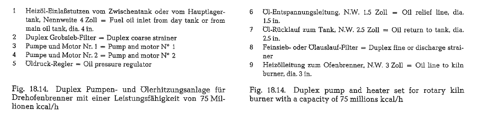
The pump and heater set heats the fuel oil from 50 oc to about 100 o -110 °C, and conveys it with the pres sure required for atomization into the kiln burner pipe. Fig. 18.14. shows a diagram of a fuel oil pump and heater set; this set works for a rotary kiln heat capacity of about 75 millions kcal/h with a through put of 128 kg/min of fuel oil, at a pump pressure of 21 atii. The entering temperature of the oil is 45 oe, and the temperature of the heated oil is approxi mately 110-112 oc.
Fuel oil pumps, oil heaters and oil strainers are com bined in this set which is mostly manufactured as a twin set (Duplex), in block construction on a common base plate, as is shown in Fig. 18.15.
The coarse side strainer with 25- 35 mesh (ASTM) sieves is placed in front of the pumps to prevent entering of solids; the fine side strainer with 100-200 mesh (ASTM) sieves is used to prevent plugging of the burner nozzles).
The operation of rotary kilns with fuel oil requires large conveying quantities and high working pres sures. Therefore, positive displacement pumps such as gear or screw pumps are used almost exclusively for this purpose. Centrifugal pumps are hardly appli cable for this operation.


Combustion of fuel oil
To calculate the combustion gases, the following fuel oil composition may be assumed:


The gas analysis performed with the Orsat-apparatus will show a different composition, since the water vapor from combustion is condensed and absorbed by the aspirating water; thus the water vapor does not appear in the total volume of the analysis.
Atomization of fuel oil
The cement industry employs mainly oil atomizing burners. Mechanical work is necessary to atomize the oil into smallest possible particles. Here, the size of the drops is of the same importance as the particle size when burning pulverized coal. The smaller the oil drops, the better the combustion. The combustion of fuel oil in the form of an aerosol occupies an inter mediate position between the surface reaction of the coal dust flame and the volume reaction of fuel gas firing.
At the oil-pressure atomizing burner, the actual oil burner lance, which atomizes the oil under high pres sure (about 45 atu) is centrally located inside the pri mary air supply pipe. At pressure atomization, the proportion of primary air is low; it amounts to about 3 % of the total combustion air, and its main purpose is to cool the burner pipe inside the hot kiln hood, and to initiate and stabilize the ignition of the oil. Pri mary air is also an instrument for shaping the flame.
Comparison between coal and fuel oil
Both kinds of fuel, i. e. fuel oil and coal, are success fully employed in the cement industry. Economic fac tors are decisive in the selection of one or the other. However, there are differences in the utilization of the heating value of the two fuels. Hansen [174] quotes the following energies which are required to
initiate a reaction between 1 kg of fuel oil, chlass ‘”S'”, and oxygen. Fuel oil ··s”” is used in Germany as rotary
kiln fuel (see table 18.10.). The storage temperature of the fuel oil is 15 oc, the oil’s setting point is 30 oc, and the content of distillate is 30 %. To make the oilcombustible, the following expenditures are required:
- For melting of the paraffines, if the storage tem perature of the fuel oil is below the setting point (melting heat is roughly 1 kcal/kg):(30 -15) x 0.1 = 1.5 kcal.
- For preheating to atomizing temperature, corres ponding 120 oc (specific heat of fuel oil is 0.5 kcal/kg. deg):(120-15) x 0.5 = 52.5kcal.
- For vaporizing of 30 % distillate (30 kcal/kg):10 kcal.
- For transforming the molecules into elements, e. to split the hydrocarbon molecules (paraffines, naphtenes, olefins, and aromatic compounds, depending on the origin of the fuel oil) into carbon and hydrogen. The heat expenditure for this pro cess (also called heat of formation), amounts to 593 kcal.

Table 18.12. contains a grouping of preheater kilns showing the additional heat consumption when using fuel oil versus coal.

Gaseous fuels- Natural gas
The most important gaseous fuel in the cement indus try is natural gas. The main components of natural gas are methane, CH4, and ethane, C2H6. The heavier hydrocarbons such as propane, C3H8, butane, C4H10, pentane, C5H12, and hexane, C6H 14, appear in natural gas only in small quantities. If natural gas contains pentane and hexane, it is called wet gas. Generally, these fractions – often down to propane – are scalped from the natural gas by liquifaction. Propane particularly is much used for domestic service and distributed in steel bottles.
Sometimes heavy hydrocarbons are denoted as nor mal (n), e. g. n-butane, whereas the remainder is called isobutane. In both cases the chemical formula is the same; the prefix ,iso'” denotes a different arrange ment of atoms in the molecule. However, the chemi cal and physical properties of the isomers are differ ent from that of the normal modification. Sulfur in natural gas occurs in the form of hydrogen sulfide, H2S. Sometimes natural gas also contains approxi mately up to 10 % inert gases as carbon dioxide, COz nitrogen, N2, and helium, He. The heating value of natural gas is in the range between 8000 and 10,000 kcal/m 3 at 16.5 oc and 30 inches Hg (US-standard conditions for natural gas).
To meet requirements for residential heating during wintertime in the U.S., natural gas is sold to industrial consumers on a non-continuous basis. This requires a second fuel source, oil or coal, for kiln operation during the winter season. Table 18.13. contains analy ses of natural gas from U.S. sources.


Southern France’s natural gas (gas wells located in Lacq) is used by several cement plants; the gas has the following composition:
95- 97.5 % CH4, 5- 2.5 % CnHm, N2 < 1 °/o; LHV = 8840 kcal/m3. These cement plants use this gas by firing a mixture of 30- 40 % coal dust and 60- 70 % gas.
Heating value
The heating value of a mixture of fuel components equals the total of the heating values of the particular components. If the fuel is a chemical compound, then the heating value equals the total of the heating val ues of the particular elements, reduced by the ther mal energy which is required for the dissociation of the molecules of this compound.
For the dissociation of the chemical bonding existing between hydrogen and carbon in the hydrocarbon moleculecules of natural gas, a thermal energy is required which equals approximately 9 % of the total heating value [174a]. The heating value of methane is:

Despite the fact that the thermal energy required for the dissociation of the hydrocarbon molecules is included in the heating value determined by the cal orimeter method, the Soviet cement expert Wal berg [174a] says that the energy expenditure for split ting the molecules is the reason which also is well known from operational experience that the flame temperature of natural gas is approximately 70-150 deg. (0 C) lower than the temperature of the coal dust flame. Therefore, when using natural gas as rotary kiln fuel, an attempt must be made to keep the temperature of the secondary air as high as possible while at the same time reducing the volume of excess air to the lowest possible rate.
Section 18.3.5. contains an explanation concerning the higher heat consumption when firing with natural gas, compared to rotary kiln operation with fuel oil or coal.
In any case, the practical result is a higher heat con sumption for clinker burning in the rotary kiln when using natural gas compared to coal or fuel oil (see table 18.14.). This example demonstrates several pre heater kilns in which seasonal changes of fuel from oil to natural gas and vice versa are practiced. An increase in the heat consumption causes also a decrease in the kiln output; this is particularly clear in the example of a kiln quoted on line 4 of the cited table, where a 1600 t/day kiln, after switching to natural gas, produces only 1500 t/day.

Flame temperature
Fig. 18.17. contains a diagram showing flame tempera tures resulting from the combustion of natural gas with varying volumes of excess air
Volumes of combustion gases


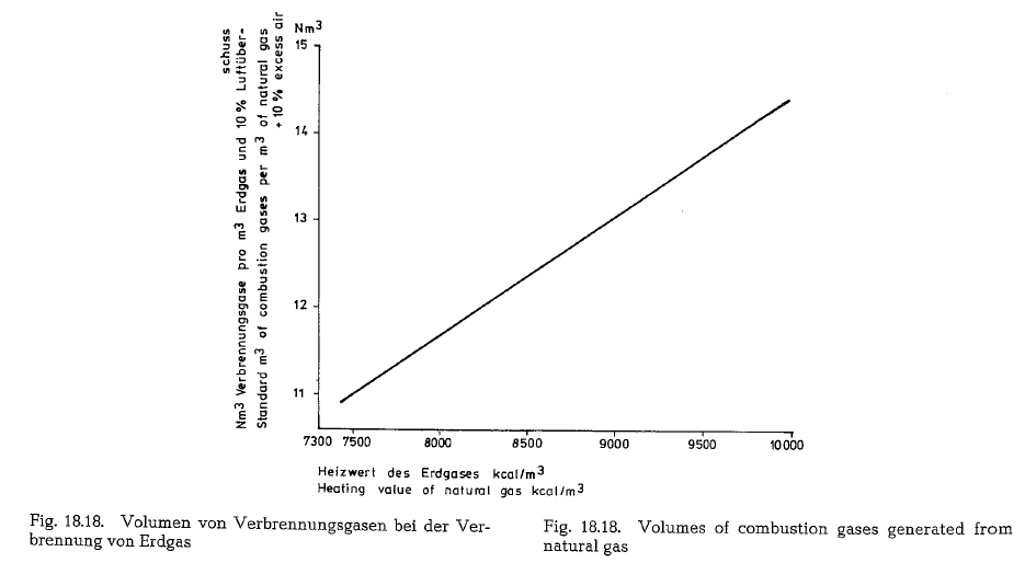
Fig. 18.18. contains a diagram showing the volumes of the combustion products in Nm3 (standard m3) at the combustion of 1 m3 of natural gas with different heat ing values, applying 10% excess air.
Table 18.15. contains specific gravities, heating values and other data concerning light hydrocarbons.
Combustion of natural gas
The following calculation of volumes and weights of combustion gases generated from combustion of natural gas, uses a gas composition as shown below (gas analysis from Southern Natural Gas Co., Bass Junction, Georgia).

Since the gas is metered saturated with water, it will be necessary to subtract 1.73 % from the total heating value to allow for the presence of water; thus the vol ume of 1 cf is apparently reduced by 1.73 %, and in our example:
(9323)(1.0000- 0.0173) = 9162 kcal/st.m3


Volumes of combustion gases from coal, fuel oil and natural gas
The combustion of coal, fuel oil and natural gas gen erates different gas volumes from the same amount of thermal units.
The following compilation contains volumes of com bustion gases (including 10% excess air), generated from the combustion of 1000 kcal of coal, fuel oil and natural gas.
1000 kcal of coal generate 1.24 stm3 of combustion gases
1000 kcal of fuel oil generate 1.31 stm3 of combustion gases
1000 kcal of natural gas generate 1.47 stm3 of combus tion gases
This demonstrates that fuel oil generates roughly 6 % more combustion gases than coal, and natural gas 18.5 %. This should be taken into consideration when sizing pyroprocessing equipment.
The higher volumes of combustion gases from fuel oil and gas also explain the higher heat consumption when firing fuel oil and especially natural gas, com pared to coal firing. This means that the air require ment for the combustion of 1000 kcal of coal is the lowest, higher with fuel oil, and the highest with the combustion of natural gas. The increased requirement of combustion air results in:
- lower flame temperatures from fuel oil and natural gas as compared to coal;
- higher kiln exit gas volumes and thus higher heat losses with the exit gases;
- higher gas velovicties inside the rotary kiln, resulting in a lower heat exchange rate from the gas to the kiln charge;
- lower specific kiln capacity and consequently higher specific heat losses by heat radiation through the kiln shell.
TO DOWNLOAD THE EXCEL SHEET AND ALL THE OTHER USEFUL BOOKS AND RESOURCES KINDLY CLICK HERE