Contents
Grinding methods in the state of development
IF YOU LIKE OUR POSTS AND WANT TO DOWNLOAD ALL OF THEM OFFLINE & IF YOU ARE INTERESTED IN DOWNLOADING THE MOST IMPORTANT BOOKS IN CEMENT INDUSTRY + ALL THE FORMULAS AND EQUATIONS AND CALCULATIONS SHEETS CLICK HERE TO DOWNLOAD THEM
Planetary ball mill
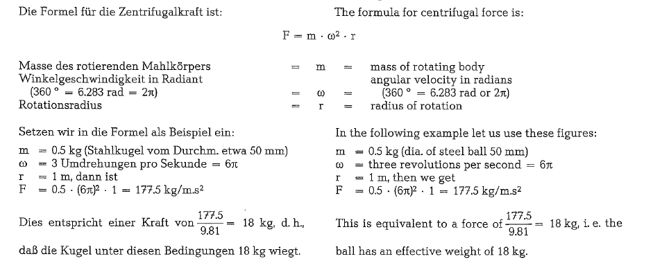
Aside from all other variables, the efficiency of a ball mill is proportionate to the specific gravity of the grinding media. The efficiency of a ball mill would increase correspondingly when using grinding media heavier than steel (spec. gr. of steel balls 7.8). Grinding with tungsten carbide balls (spec. gr. 14) results in proportionately higher mill efficiencies; however, such grinding media are too expensive [148b]. This relationship leads to the following premise: replace the higher specific gravity of the grinding media by centrifugal force.
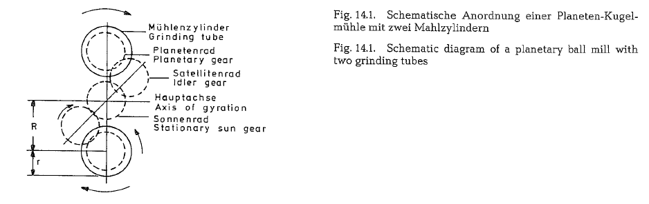
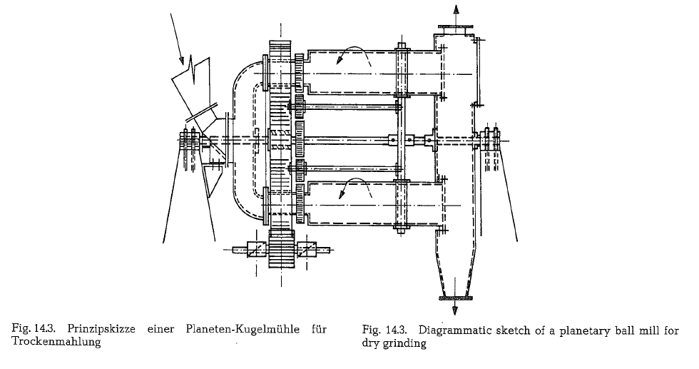
This is the fundamental idea of the centrifugal or pla netary ball milL A planetary ball mill consists of two or more parallel grinding tubes, performing a gyros copic movement around a common axis of rotation. Fig. 14.1. shows a schematic of the cross-section of a planetary ball mill with two grinding tubes
The radius of gyration R. is larger than the radius of the grinding tubes, r. The grinding media in the grind ing tubes are inside a field of centrifugal force. The induced mass forces of the grinding media are consi derably larger than the pull of gravity; under these circumstances the latter is almost non-existent for the grinding media.
Thus the content of the mill is influenced by two forces:
- The centrifugal force generated by gyration of the grinding tubes around the axis (main axis).
- The centrifugal force generated by rotation of the grinding tubes around their own
When combining these two centrifugal forces, it is possible to reduce considerably the sizes of the grind ing tubes and media.
It might be further concluded that:
- The mill output is proportionate to the third power of the speed of rotation around the axis of the assembly.
- The part of the trajectories of the grinding media is determined by the ratio of the radius of gyra tion (R) to the radius of the mill tube (r).
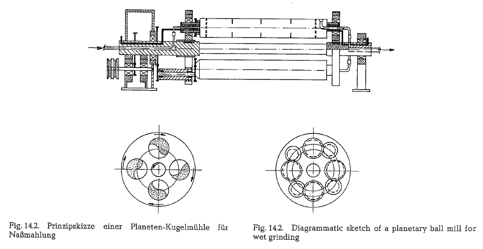
Fig. 14.2. shows a diagrammatic sketch of a planetary ball mill equipped with four grinding tubes for wet grinding of an iron oxide dispersion [148d]. The length of the grinding tubes is 1000 mm; the inside diameter is 150 mm. A transmission gear is located between motor and main shaft. The rotation of the planetary assembly is opposite to that of the mill tubes. A sys tem of hollow shafts serves for the continuous feed ing and discharging of the grinding tubes. The plane tary assembly rotates at 366 rpm. The speed of rota tion of the grinding tubes, when rotating opposite to the main assembly is 725 rpm. The power input for one grinding tube is 29.5 HP (22 kW), and for the total mill 118 HP (88 kW). Proceeding from the effective throughput of this planetary mill, it can be shown that the planetary ball mill demands only about 3 % of the grinding energy a regular tube mill would require for the same fineness and output of iron oxide [148e].
A planetary ball mill equipped with three grinding tubes and with a grinding capacity of 5.5 t/h of hard goldbearing quartzite (grinding from approximately 7 mm feed size down to 74 micron) has a weight of 1 t [148f]. A conventional ball mill would show a weight of approximately 25 t for this througput.
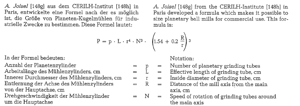
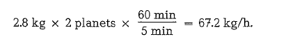
This formula demonstrates that a higher mill output requires a larger mill tube diameter as well as higher revolutions of the planets around the main axis. Start ing data for the following example are test results collected from a laboratory mill. Batch grinding with 160 rpm and 2.8 kg charge of cement per mill tube (2 grinding tubes a 20 em length) and 5 minutes grinding
time, resulted in a fineness of 3000 Blaine. Under these conditions, and when operated continuously, this mill would have a capacity of
A mill with 6 planetary tubes and with a tube length of 60 em would show an output of 67.2 x 3 x 3 =
604.8 kg/h. At twice the speed of rotation (N = 320 rpm) the mill output would be 604.8 x 23 = 4838.4
kg/h, and at four times the speed of rotation (640 rpm) the output would result in
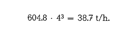
This mill would require a construction volume of approximately 1.5 m3
Advantages of the planetary ball mill: low manufac turing and installation costs; low weight of the mill; control of fineness by varying the speed of rotation; grinding balls of planetary mills can be four times smaller than that of regular ball mills.
Disadvantages: the small weight ratio of grinding media and mill lining to the mill throughput requires frequent replacement of the worn out steel; it is likely that the critical grinding temperature will be exceeded when grinding cement; however, this could be prevented by intensive air cooling of the grinding tubes; the design of the continuous feeding and discharge arrangement has yet to be stabilized.
Although the planetary ball mill is not a new idea, much development work is being presently per formed in many countries to make this mill commercially feasible
The South African Chamber of Mines operates a pla netary ball mill for grinding of gold ore with a drive motor of 1000 kW
According to recent reports [114a] the 1000 kW machine has operated extremely well.
Fig. 14.4. shows a picture of an installation of the 1000 kW planetary ball mill, including foreground, and variable speed hydraulic gearbox; coupled transfer gearboxes with disc brake on left hand box; in center feed chute and spiral-type feeder. Either side and slightly below of spiral feeder the excentric shaft and main bearing in the U-frame; and the hydraulically tensioned bolts to hold the mill tube at the top of the mill frame.
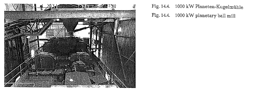
Process results are very interesting -over 90 t/h of minus 19 mm feed milled to 65% of minus 75 J..LID in a single pass, with the mill 50 % full of 50 mm dia. grinding balls (volumetric), run at 198 rpm, and draw ing 747 kW (power input).
The mill linings are generally good for over 150 hours with less than 4 hours downtime for switching lining tubes. The grinding ball consumption is about 1.2 kg Mn steel per ton of mill feed, and the liner wear is about 0.2 kg/t. The ball wear is still rather high, and is to some extent due to poor casting of the balls, and resultant fracturing of them. The mill feed is Witwa tersrand hard quartzite with a specific energy con sumption in this kind of mill of 30-35 kWh/t
Comminution by exploding sparks
In certain situations a flash voltage wave or electric spark can generate an extremely high gas pressure. This pressure is produced by the thermal expansion of a confined gas which is heated by the electrical discharge to an extremely high temperature. An even higher pressure can be produced when this high tem perature causes a confined liquid to be converted into the gaseous state. For this purpose, simple electrical circuits can be used for producing sparks between underwater electrodes with voltages of 10,000 to 100,000 Volts [148i].
The powerful release of energy called “‘exploding spark”‘ results in a percussive compression wave of great mechanical force, accompanied by a sonic wave as well as by a flash, generated by the high tempera ture. This electrohydraulic phenomenon, also called underwater lightning, appears to have important engineering applications.
By means of an “”exploding spark”” an electrical signal can be converted into a mechanical motion with a time lag of 1 to 10 x 10-6 seconds. The impulse generates a high pressure wave which moves with a velocity of about 15,000 meter/s, and which can be compared to an explosion in the range of 400,000 kW. Thus, a shattering power approximately 18 times more powerful than that of nitroglycerine is produced. Many experiments involving these principles have been conducted to disintegrate rocks and other dense solids.
Research work performed by the Office of Ordnance Research, U.S. Army Ordnance Corps, indicated that the pressure developed in underwater sparks experi ments was of the order of 5,000 atmospheres. An increase in the diameter of the spark channel pre sumably requires the arrangement of a multiplicity of spark gaps to boost the power of the underwater pressure wave [148k].
Based on these experiments and on theoretical calcu lations it was concluded that to reduce 1 t of lime stone from a particle size of approximately 45 rom to particles of 1 micron in size, the energy requirement would be only 8- 10 kWh/t.
With these figures the efficiency of this new kind of comminution can be calculated and compared to con ventional size reduction involving grinding of cement raw mix in a tube mill. For this example cement raw mix consists roughly of 80 % limestone and 20 % marl; marl is assumed to have the same grindability as limestone.
Particles 1 micron in size have a specific surface of 30,000 cm2/gram (see Fig. 10.2.}. The specific surface of cement raw mix with a fineness expressed as 14% residue on the 170 mesh sieve equals 2400 cm2/gram (see Fig. 10.3.}. The grinding energy required to prod uce 1ton of cement raw mix can be assumed with 23 kWh/t, whereas the size reduction energy required to produce 1 ton of disintegrated limestone by electrohydraulic comminution is, as previously quoted, 8- 10 kWh; for this calculation a figure of 10 kWh/t will be applied. To get simpler figures, square meters will be used in the following calcula tion, instead of square centimeters;
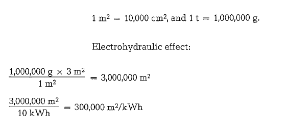
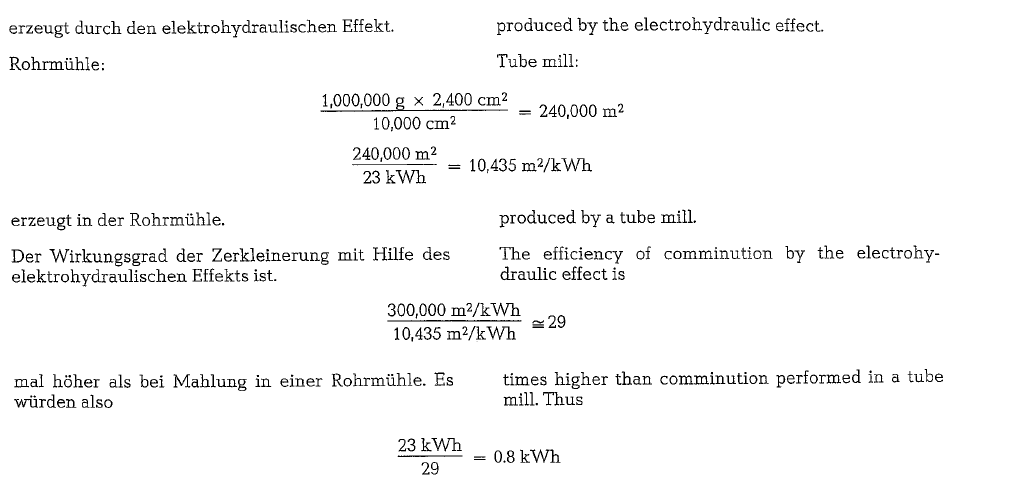
would be required to produce 1 ton of cement raw mix with 2400 Blaine applying the electrohydraulic effect for particle size reduction, instead of 23 kWh/t when grinding in a tube mill. This is a very impres sive figure; however, it should be realized that the process of electrohydraulic comminution has yet to be developed to the extent of performing size reduc tion on a practical scale.
Grinding systems with the High-Pressure Grinding Roll
The comminution of brittle material between two rollers in a material bed deals with, in comparison to traditional methods, an energy saving process using well known principles and it requires no exotic equipment. The heart of such a system is the high pressure grinding roll which is a part of Krupp Poly sius’ program.
The principle of this grinding machine is shown in Fig. 14.5. It consists essentially of two smooth rolls, with a diameter-to-length ratio of about 3, revolving in opposite directions. Both rolls run in antifriction bearings and are guided in slide supports. One roll has a fixed, adjustable mounting. The pressure required for the grinding process is applied by a hydraulic system via the other roll. The rolls react very quickly to any tramp metal in the bed of mater ial by withdrawing of their normal working position and then returning just as rapidly to their original place. In the illustrated version, the rolls are driven by DC motors via cardan shafts and shaft-mounted planetary gear units. The material is fed from above through a hopper into the gap between the rolls. A similar roll crusher, but with grooved rolls is shown
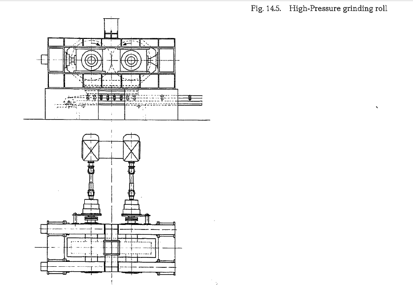
in section 3.10. of this book. The ground material emerges from between the rolls as a compacted cake, whose consistency depends on the grinding pressure employed. This cake contains both fine and coarse particles and must be sent through a second size reduction machine, either merely to disagglomerate the cake or for further grinding.
When considering the reasons for the remarkable saving in energy achieved by the high-pressure grinding roll compared with the ball mill, the differ ences between the two processes must be examined.
Although in both cases the particles of material are subjected to the grinding force in the same way, namely through compressive and shearing forces within a bed of material. it is possible that a higher proportion of shearing force could be generated in the ball mill, which would have an unfavorable effect.
However, the main difference is that in the ball mill
the grinding and conveying of the material takes
place stochastically. The grinding media possess widely varying kinetic energies; the energy utiliza tion deteriorates, if the energies applied are either too great or too small, and the specific energy con sumption must increase. In the grinding roll. how ever, the high pressure applied to the bed of material is determined and can be set to the optimum intens ity.
Three types of comminution occur:
- general reduction of the particle size
- reduction of the strength of individual particles by cracking
- production of a high portion of fine
Two areas of application have been foreseen for the grinding roll:
- as a primary grinding unit for existing grinding plants,
- as an autonomous mill for finish-grinding.
Primary grinding with the High-Pressure Grinding Roll
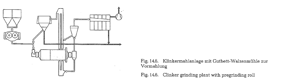
Fig. 14.6. illustrates a ball-mill system equipped with dynamic and stationary separators. In order to relieve the ball mill of the primary or coarse grinding, it is preceded by a grinding roll. A considerably higher degree of comminution is achieved with the grinding roll than with conventional jaw, cone or roll crushers because it produces a substantial portion of fines. This can be seen in the particle-size distributions shown in Fig. 14.7. for a roll crusher and for the grind ing roll. The solid curves represent the feed material, the dotted curves the material produced by each machine. In the pair of curves numbered 2 (for the grinding roll), the high portion of fines is noticeable. This high output of fines is always achieved, even with a relatively low energy input, and represents the advantage of the grinding roll compared with other grinding systems.
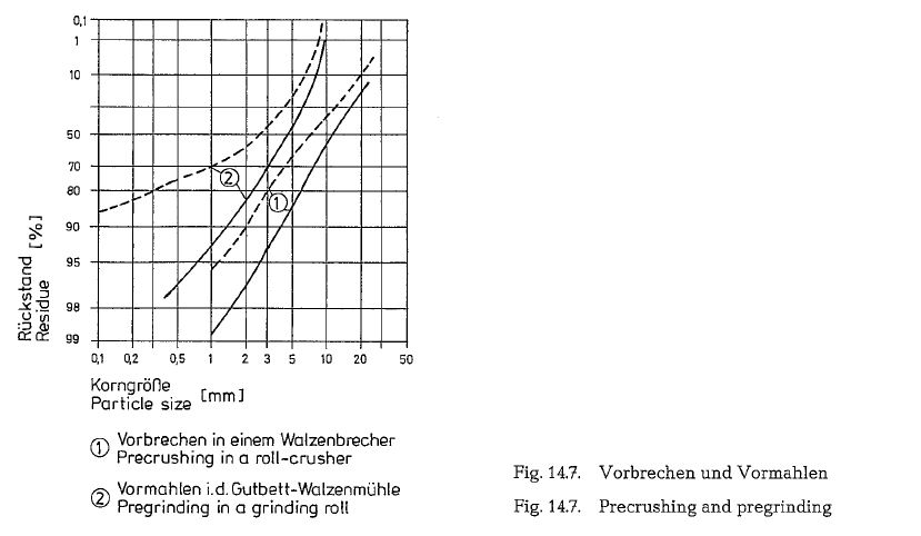
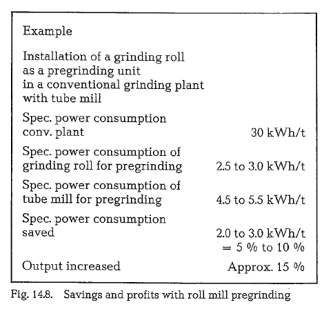
Fig. 14.8. shows the extent of the energy savings and improvement in output which can be attained when using the grinding roll as a primary mill. The figures given are based on a conventional ball-mill grinding system with a specific energy requirement of 30 kWh/t. The grinding-roll primary grinding stage requires about 2.5 to 3.0 kWh/t. The same degree of primary grinding in a ball mill would require about 4.5 to 5.5 kWh/t. The saving in energy is therefore 5-10% of the total energy requirement. Further more, the installation of the grinding roll as a primary mill increases output by about 15 %.
According to the manufacturers, these are very conservative estimates. They are convinced that further development and optimization will lead to significantly better results in the near future. The tests carried out to date support this view.
Finish-grinding with the High-Pressure Grinding Roll
For the further object of the grinding roll -the fin ish-grinding of brittle materials (in this case clinker) -various systems could be used.
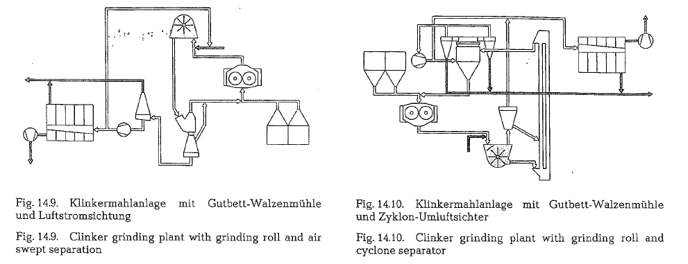
Fig. 14.9. illustrates a plant in which the grinding roll operates in a closed circuit system. The compacted cakes of material are fed to a hammer mill and disag glomerated. The particles are then carried in the air stream to static primary and finish separators. The tailings discharged from the separator are returned to the grinding roll for further size reduction. The fin ished product carried in the airstream after the separ ators is collected in cyclones and filters. Instead of the hammer mill, a ball mill could also be used in this system.
The advantage of such a system, besides the attaina ble reduction in energy consumption, is the simple mechanical design of the plant. Furthermore, it is also possible to grind moist materials, which are dried by hot air in the hammer mill.
Another possible application of the grinding roll is illustrated in the flow chart shown in Fig. 14.10. Here too, the compacted cakes produced by the grinding roll are disintegrated in a hammer mill. The hammer mill is dedusted and the dust-laden air passed through a separator to remove the coarse particles. These are returned to the grinding circuit. The air stream after the separator is led to a filter, where the finished product is collected.
Most of the disintegrated product in the hammer mill is discharged by gravity and fed to a dynamic separa tor by bucket elevator. Here the material is separated into finished product and tailings. The tailings are returned to the grinding roll for further size reduc tion.
In this system, a ball mill or similar machine could also be used instead of the hammer mill for disinte grating the compacted cakes of material.
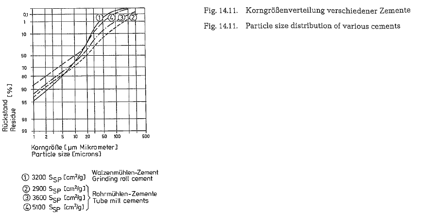
The cements produced in the described systems dis play – similarly to those from roller mills -a very steep particle size distribution. Fig. 14.11. shows a grinding roll-cement and three Portland cements with the qualities PZ 35 F, PZ 45 F and PZ 55 (accord ing to German standards DIN 1164) produced from the same clinker as the grinding roll-cement by an industrial two-compartment separator mill. The spe cific surface values are:
grinding roll-cement 3.200 cm2/g ace. to Blaine con ventionally-produced cements from ball-mill systems 2.900 cm2/g, 3.600 cm2/g, and 5.100 cm2/g.
The grinding roll-cement has by far the steepest par ticle size distribution line and therefore the narrow est particle size distribution, which very positively affects its strength development.
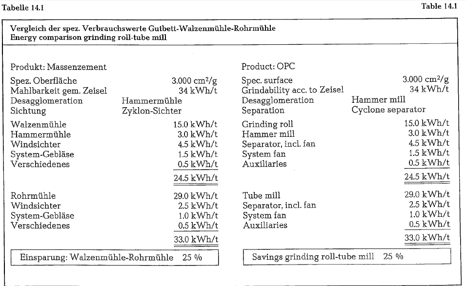
The possibilities offered by a system such as that illustrated in Fig. 14.10. are shown in Table 14.1. Here, two systems are compared on the basis of a clinker with a grindability of 34 kWh/t according to Zeisel. The first system consists of a grinding roll, a hammer mill for disagglomerating the cakes of material, a cyclone separator, the system blower and the auxil iary units. The total energy requirement of this sys tem is 24.5 kWh/t. The second system consists of a tube mill, a cyclone separator, the system blower and the auxiliary units. Under identical operating condi tions, this system requires 33 kWh/t. The attainable savings of a grinding roll-system compared with a tube mill-system are – referred to cements of the same specific surface -approx. 25 %.
The questions of wear and operational reliability of the grinding roll can at present only be answered on the basis of the results obtained with the pilot plant. Since the commissioning of this unit, no measurable wear has been suffered by the roll jackets.
With the wear-resistant materials available today for instance high chrome alloy steel -the problem of wear can be effectively mastered. Furthermore, the cylindrical shape of the grinding rolls means that there is no relative movement of a “shearing” nature between the grinding surface which could promote wear.
As the effeciency of the grinding roll depends on the surfaces of the rolls being as smooth as possible, a device will be supplied with the grinding roll which will permit the surfaces to be smoothed without dis mantling the rolls. It is also being investigated whether worn out rolls can be returned to their ori ginal form by hard facing {rewelding).
The noise emission level of a grinding roll unit is con siderably lower than those of a ball mill.
Of course, only long-time tests can prove the opera tional reliability of the grinding roll. However, its mechanical simplicity should guarantee a long and reliable service life [114c, 114d].
IF YOU LIKE OUR POSTS AND WANT TO DOWNLOAD ALL OF THEM OFFLINE & IF YOU ARE INTERESTED IN DOWNLOADING THE MOST IMPORTANT BOOKS IN CEMENT INDUSTRY + ALL THE FORMULAS AND EQUATIONS AND CALCULATIONS SHEETS CLICK HERE TO DOWNLOAD THEM
Thank you for pointing out that the planetary ball mill is low in weight. Grinding seems like an important step in making sure the metal or glass is smooth. Hopefully, companies would make sure the people they are hiring to grind are the best possible.