Contents
Air separators
IF YOU LIKE OUR POSTS AND WANT TO DOWNLOAD ALL OF THEM OFFLINE & IF YOU ARE INTERESTED IN DOWNLOADING THE MOST IMPORTANT BOOKS IN CEMENT INDUSTRY + ALL THE FORMULAS AND EQUATIONS AND CALCULATIONS SHEETS CLICK HERE TO DOWNLOAD THEM
Separation as performed by mechanical air separators is the division of a given material stream into two separate streams, using air as the carrying medium. Hereby one stream should contain only fine particles, and the other, as far as possible, only coarse particles. To perform this funktion, the separator feed must be evenly distributed inside the separator, and subjected to classifying forces, which should be variable. The classifying forces acting upon the various solid parti cles of different sizes, are described farther down.
The dispersion separator, (also called the mechanical air separator) is the most representative air separator in the cement industry. This kind of separator utilizes a distribution plate to disperse the feed material into the separating space. There are various designs of feeding arrangements of the mechanical air separator. The majority of the mechanical air separators gener ate the circulating air inside the separator itself; therefore they are also called circulating air separa tors. Mechanical air separators can also be supplied with separating air generated outside the separator.
The operation of the air separator is based on the fol lowing principles:
The action of an air current of a certain velocity upon a mass-particle is proportional to the surface pre sented by this particle to the air current, thus to the square of the mean dimensions of the particle. The action of the force of gravity upon a mass-particle is proportional to the volume, thus to the cube of the mean dimensions of the particle. Therefore the effect of the force of gravity increases faster than that of an air current of constant velocity. If these two forces are concurrent, i. e. when particles being in a state of free fall are exposed to an ascending air current, the force of gravity will prevail over the effect of the air current as particle dimensions increase. On the other hand a properly adjusted air current will oppose the force of gravity and lift up the finest mass-particles
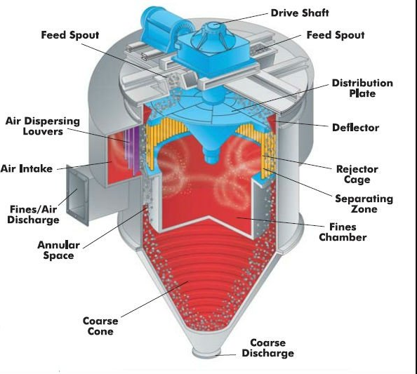
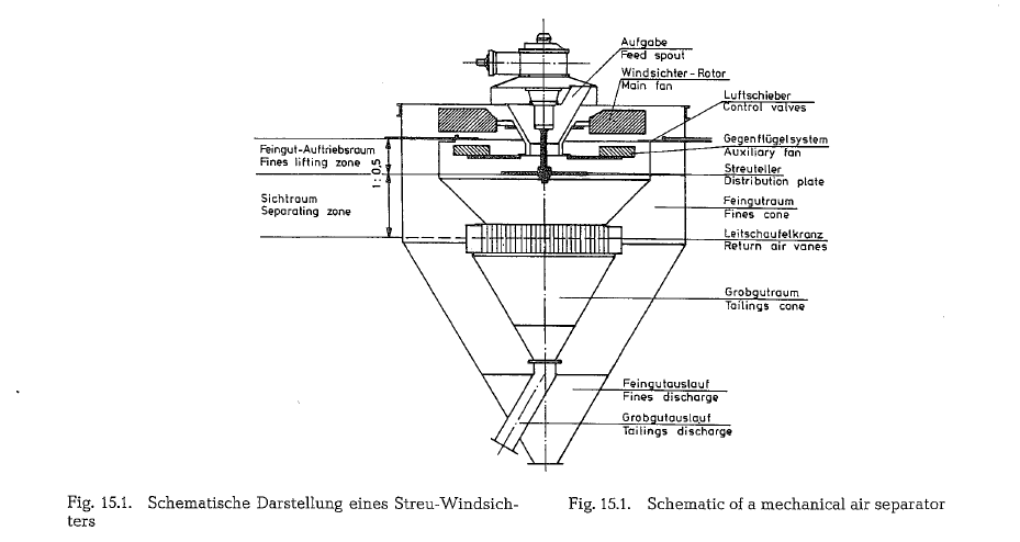
Fig. 15.1 shows a typical mechanical air separator. The separator feed passed through the hollow feed spout and drops by gravity to the distribution plate. The drive shaft operates through the hollow feed spout. The separator main fan creates a continuous circulating air current into which the distribution plate disperses the separator feed.
Materials leaving the distribution plate are acted upon by three forces (see Fig. 15.2.a.):
- The centrifugal force, Fe
- The force of the ascending air current, Fd
- The force of gravity, Fg
Air velocity, volume of air, and speed of rotation are important factors in the separating of the fine parti cles from the coarse ones.
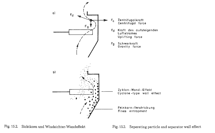
The distribution plate must impart to the particles a centrifugal force of sufficient magnitude to throw the particles into the separating zone faster than new feed is received at the hub of the distribution plate. Radial dispersing ribs welded on the distribution plate prevent sliding of the separator feed. As heavier and larger particles are thrown farther outwards and their centrifugal force is decreased, they settle by act ion of gravity. If they hit the separator wall, cyclone type wall effect forces them down into the tailings cone [150].
Fig. 15.2.a. shows the three forces acting upon a parti cle in the separator. Fig. 15.2.b. illustrates the cyclone-type wall effect inside the separator as well as the entrapment of fines by accumulation of coarse particles; this circumstance contributes to a blurred dividing line between fine and coarse particle frac tions.
Fine particles up to a certain size are lifted by the ascending air current and pass between the blades of both the auxiliary and main fan into the outer separa tor cone which is also called fines cone. Underneath the separating zone the return air vanes are located. The main fan moves the air from the fines cone into the separating zone through this grating of vanes. The separation of the fines from the descending air current in the outer separator cone is performed by decreasing the air velocity as well as by change of direction of the air current. Because of the low rate of descent of the smallest particles, these fractions are always suspended in the air current and therefore a portion of fine dust is continuously circulating and a fraction of the fines comes into the separator tailings.
Main fan, auxiliary fan, and distribution plate are mounted on a common shaft. The auxiliary fan acts against the intake air current caused by the main fan; this counteraction can be controlled by the number of blades of the auxiliary fan. A large number of blades causes a stronger counteraction, i. e. it chokes the upcoming air current more than a smaller number of blades. An adjustment in the number of blades is necessary, when switching to other types of cement. The grinding plant must be shut down to accomplish this.
Another possibility for fine adjustment of air separa tors is offered by the horizontal control valves which make it possible to change the cross section of the ascending air current. By adjusting the air control valves it is possible to choke the air current and shift the classification boundary closer to the separator fines. This fine adjustment can be accomplished with out stopping the operation of the grinding plant [151).
The blades of the main fan are also adjustable; adjust ment can produce a larger or smaller fan diameter. Maximum outward position of the blades with air control valves wide open, results in increased separa tor capacity, but with the tendency to yield a coarser product. Any desired product fineness can be attained when adjusting the blades of the main fan, the blades of the auxiliary fan, or the air control valves; however, the capacity of the air separator is reduced.
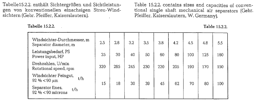
Separator manufacturers suggest that the fraction of fines present in the separator feed should be approxi mately 70 O/o; and, a circulating load of about 200 % is recommended [152].
The separator finished product is judged by the amount of coarse particles in the fines.
The criterion for separator capacity is the amount of fines which pass into or are still present in the sepa rator tailings.
The finer the particle size of the finished product, the lower the separator’s production capacity. The effi ciency of an air separator depends upon the type of mill working with the separator. The higher the length to diameter ratio of the mill consequently the lower the circulating load- the better the selectivity of an air separator [153, 154].
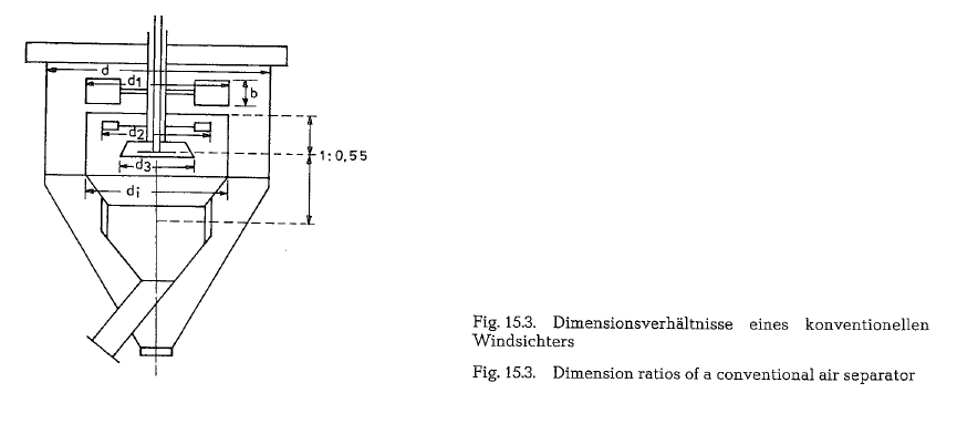
Dimension ratios of conventional air separators
Fig. 15.1. left, shows separating and lifting zones for the separator fines. The heights of these two spaces are of particular significance for the classifying work of an air separator. The upward air current should have the opportunity to remain as long as possible in interaction with the separator feed dispersed by the distribution plate, or in other words, the residence time of the separator feed in the air current should be extended to create a more selective action. The separating zone should have a maximum height to achieve this result. In the fines lifting zone of the separator the classified fines are being elevated and thrown over the brim of the inner cone into the fines cone; this should happen very fast. For an effective classifying action the ratio of the heights of both zones, i. e., the height of the separating zone to the height of the fines lifting zone should amount to a maximum of 1 : 1. A better classifying action will be attained with a ratio of 1 : < 1. The ratio of heights of both zones of the separator shown in Fig. 15.1. is 1 : 0.5, which provides an acceptable classifying perform ance. Separators with a height ratio of 0.8 : 1 to 0.5 : 1 and below, show an unsatisfactory classifying action.
The following suggestions are made by Tanaka [155] for the dimension ratio of some structural elements of a conventional mechanical air separator (see Fig. 15.3.).
According to the scheme, the dimensions shown should comply with the following ratios:
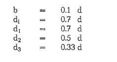
Tanaka is not specific about the height ratio of the separating zone of the fines lifting zone, but the pic ture shows that this ratio equals 1 : 0.55; this indicates efficient classifying action.
Air separator sizes
Conventional mechanical air separators are available in sizes up to 10m in diameter and with capacities up to 250 t/h (metric) of separator fines [156]. Generally air separator sizes are specified by the diameter of the outer separator casing.
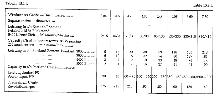
Table 15.2.1. contains separator sizes and capacities for cement raw mix and Portland cement; these are conventional single shaft mechanical air separators, manufactured in the United States.
Specific power requirement of air separators
The specific power requirement of mechanical air separators depends upon the quality of separator feed, the circulating load, and the desired fineness of the finished product. Figures in the magnitude from 2 to 6 kWh/t (metric ton) are quoted; this includes also separators with air supply from outside [157].
Air separators with speed controlled auxiliary fan
The essential difference of this kind of dispersion type separators consists of the specific design of the adjustment to control the separator fines. For this type of separator design, the auxiliary fan has a separate drive with variable and stepless speed con trol. The distribution plate or ring is attached to the shaft of the auxiliary fan. The speed of the auxiliary fan amounts to 50- 60 % of the main fan’s speed; the speed of the main fan is constant. The range of speed of the auxiliary fan is about 1:3; in larger units this ratio decreases to 1:1.75. The direction of rotation of the auxiliary fan is the same as that of the main fan. So as not to inhibit the action of the distribution plate, the number of revolutions of the auxiliary fan should be kept above 80 rpm. To assure constant speed of the distribution plate, seperators with indivi dual drives for the distribution plate were developed [158].
The main shaft is hollow and contains the built-in shaft of the auxiliary fan. The double drive through core and sleeve shaft would complicate feeding the separator from above and therefore the side-entry of the feed to the distribution plate and the separating zone was developed. The blades or wings of the auxil iary fan are radially adjustable and counteract the suction caused by the main fan. When changing the speed of the auxiliary fan it is possible to control the suction and thus to alter the range of fineness at will. Increasing the speed of the auxiliary “fan (thereby decreasing the circulating air current) causes fewer fines to be picked up from the dispersed separator feed; the particle sizes of the fines are smaller and the amount of fines lower. By decreasing the speed of the auxiliary fan (thereby increasing the circulating air current) more fines mill be picked up from the separa tor feed; however, in this case the particle sizes of the fines shift more toward the range of the separator coarses, thus reducing the circulating load. By simply adjusting the speed of the auxiliary fan the fineness of the end-product can be changed without interrupt ing the operation of the mill and separator. With this kind of separator, Blaine numbers from 2000 to 7000 cm2/gram can be produced, depending upon the nature of the mill feed.
The circumferential speed of the main fan amounts to about 40 m/s, and that of the auxiliary fan is in the range from 18-30 m/s. These figures are useful for determining or checking the revolutions of separa tors of various sizes.
Sizes and capacities of speed controlled separators
Table 15.5.1. contains a capacity diagram for various sizes of speed controlled mechanical air separators (Heyd separator). This diagram was developed by the Christian Pfeiffer Company in Beckum, W. Germany [159].
The geometrical, mass-related comparison surface 0’m• shown in the capacity diagram was determined by evaluation of a particle size distribution curve, from a system of coordinates with linear spacing on both sides. Thereby it was started from a mass-related geometrical surface which is calculated as:
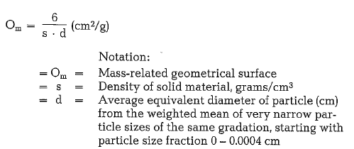
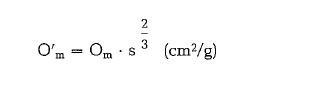
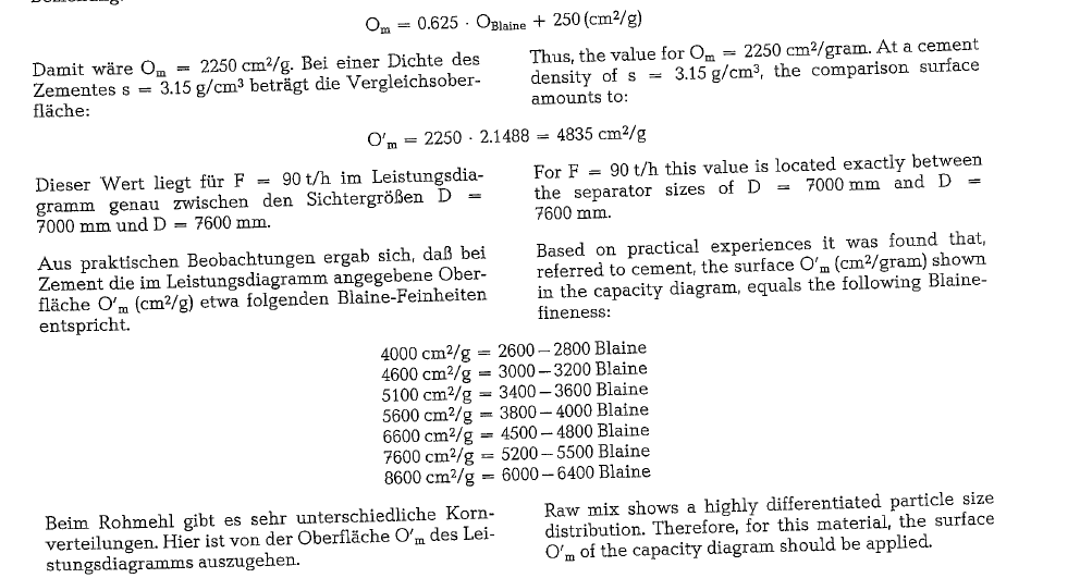
The comparison surface refers exclusively to solid material with a density of s = 1 gram/cm3. In the cap acity diagram the following relation is valid for the conversion of the geometrical surface Om to the geo metrical comparision surface 0’m·
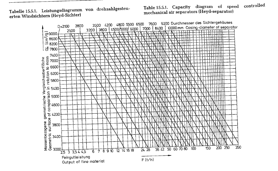
Example for the selection of a separator according to the capacity diagram:
Determine a separator size for a capacity of 90 t/h (metric) of cement with a fineness of 3200 Blaine. Within the limits of 2000 to 6000 Blaine, the following aproximated ratio exists between the geometrical surface and the Blaine-test:
In the USA, the Heyd-separator is manufactured by the Fuller Company, Bethlehem, Pa.
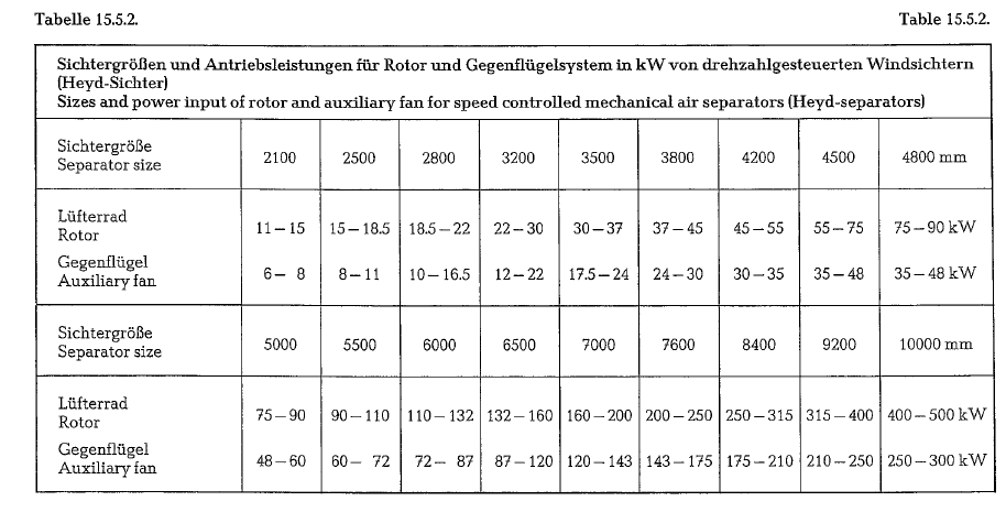
The Christian Pfeiffer Co. manufactures the following separator sizes .with double drive i.e. with rotor and speed controlled auxiliary fan, which are mainly employed as cement separators (see table 15.5.2.).
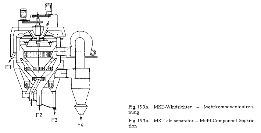
Multicomponent separator MKT
The Chr. Pfeiffer Company, Beckum, W. Germany, has developed a separator which has been in the market for several years. In this MKT separator are combined all constructive attributes of the already described separating systems of the speed-controlled mechani cal air separators and the cyclone separators: blower is located outside the separator housing, only one cyclone is applied, and several concentric separating hoppers which, fit into one another, repeatedly clean the circulating air. When separating especially fine cements the circulating air flow must not be throttled so that the separator can attain a high selective effi ciency. In comparison with the changed procedure,i.e. a parallel fines separation in the cyclone separator, besides the coarse material current, several fin ished currents F1 to F4 are obtained which have a quantity ratio of 1:3 whereas its fineness increases accordingly. Therefore it is called MKT, which means “Multi-Component-Separation”. This gives some variation possibilities concerning the granulometric composition and fineness of the expected final pro duct or the final products in case of cement splitting in various cement fractions. The cement cooling is effected by means of a fresh-air intake just as in the cyclone separator.
When comparing the sizes of the MKT air separator with those of the Heyd separator, which also is being build by the same manufacturer, the MKT separator sizes which diameters of the external upper housing are roughly 35% smaller than that of the Heyd sepa rator, yield the same capacities.
On the other hand, the MKT separator is furnished with three drive motors, two of which are of the expensive speed controlled type, which naturally affect the price of this type of separator [159.1].
The above quoted data are based on informations supplied by the manufacturer.
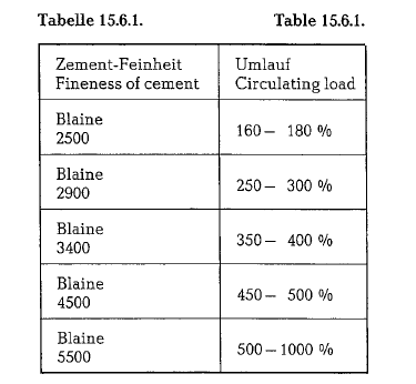
Circulating load and fineness of cement
Table 15.6.1. contains figures of circulating loads when separating the quoted Blaine numbers of cement, using a speed controlled air separator.
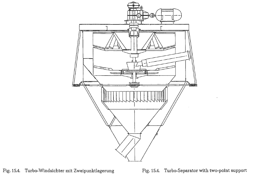
Turbo-Separator Turbopol (Krupp Polysius AG)
This separator is furnished with an auxiliary fan driven by a separate drive arrangement. The hollow shaft and the core shaft are attached to a common, two motor, totally enclosed spur gearing drive. The rotating parts are not freely floating but are held by a flexible twopoint support arrangement – on the top in the gear casing, and down on the shaft’s end. This is accomplished by a structure inside the separator (Fig. 15.4.).
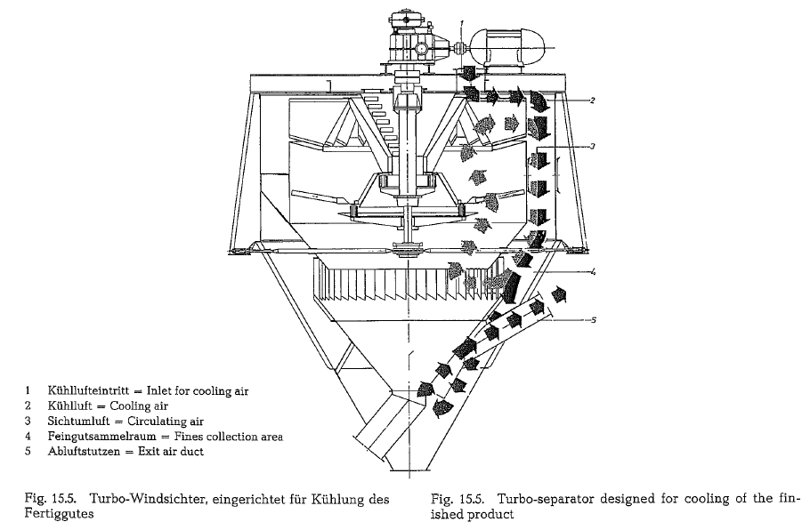
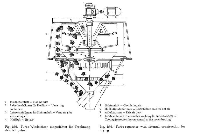
A special feeding arrangement has been developed to improve the separation process by a uniform distribu tion of the separator feed, from the distribution plate into the circular separating space area; this arrange ment guarantees an almost ideal material distribution around the circumference. Fig. 15.5. shows a Turbo separator arranged for cooling of the finished prod uct, and Fig. 15.6. shows the same separator supplied with internal construction for drying [159a].
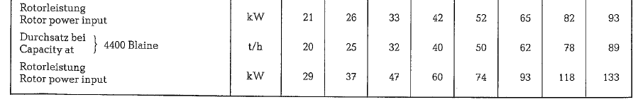
Krupp Polysius manufactures Turbo-separators in sizes of 3200- 8500 mm 0. According to the manu facturer, the maximum capacities amount to 160 t/h of cement with a fineness of 2800 cm2/g Blaine, and 200 t/h of raw mix with a fineness of 12 % residue on the 88 micron (No. 170) sieve for the separator size of 8500 mm 0. The specific separation capacity for all separator sizes of the Turbo-separator pro m2 separator surface amounts for cement with a fineness of approx. 2800-3000 cm2/g Blaine, 2.6-2.8 t/m2 · h, and for raw mix with the above quoted fineness, 3.6 t/m2 ·h
The specific energy consumption of the Turbo separa tor amounts to 1.6-1.8 kWh/t of cement with 2800 cm2 Blaine.
Cyclone air separator (KHD Humboldt WedagAG)
With this type of separator it is possible, to achieve fine product capacities of up to 500 metric t/h, apply ing only one separator unit.
For this type of separator design, the cross-current separation process with distribution plate and speed controlled auxiliary fan, was retained from the conventional air separator.
In contradistinction to the conventional air separator, the cyclone air separator is supplied with separating air in closed circuit from an outside located blower and the fines are separated in several cyclones.
According to the manufacturer, the division of the two processes, i.e. separation and precipitation, results in the following advantages:
- The specific load of the separating zone can be increased; this results in throughput capacities of separator fines up to 500 metric t/h, with only one separator unit.
- Variations in the separator feed (circulating load) do not affect the fineness of the separator’s prod uct; therefore, the quality of the fines remains unchanged.
- Since the circulating load is reduced to the capacity of the centrifugal system, the separator runs almost without vibrations.
- The separator is fed centrally; there is no adverse influence to the separation process by supplying the separator feed laterally.
- Omission of the hollow shaft drive allows for a considerably simpler suspension of the distribu tion plate and of the auxilary fan.
- Precipitation of the fines in high efficiency cyclones results in a better separating effect, since less dust particles are carried by the circulating air.
- The blower located outside, works with a better efficiency than a fan working inside the seperator
- By precipitating the fines, the usually high wear rate of the auxilary fan is eliminated
- During operation of the separator, alteration of the product’s fineness can be achieved by chang ing the revolutions of the auxiliary fan as well as by changing the circulating air volume through adjustment of the blower vanes or of the damper (see Fig. 15.7.).
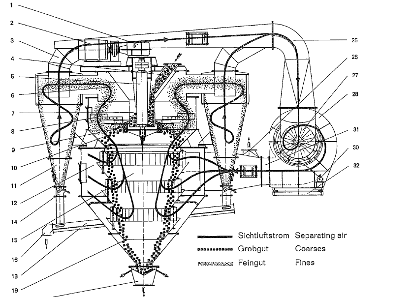
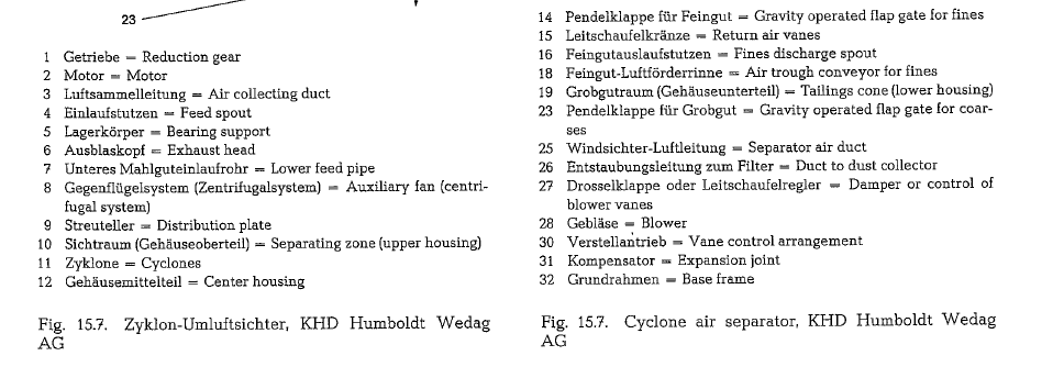
Cement fineness can be controlled within a range of 2500 and 7000 Blaine. Control of the circulating air allows for a limited change in the particle size distri bution at the same Blaine number.
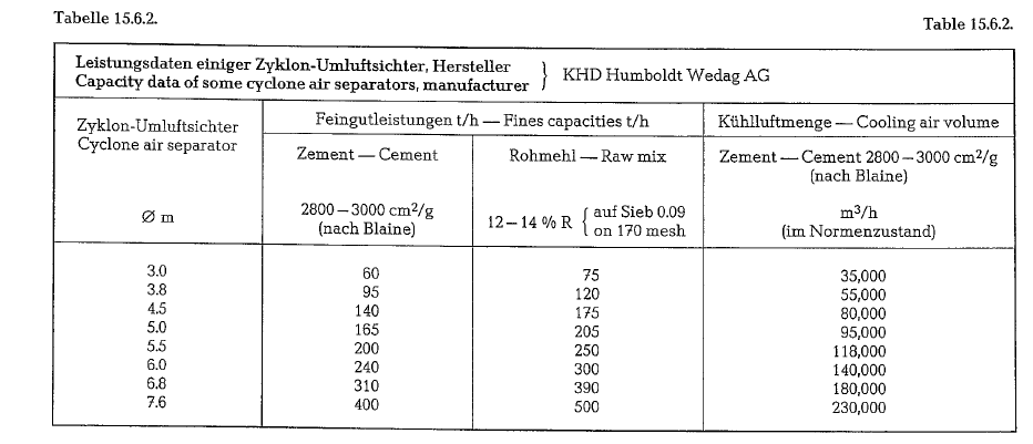
The cyclone air separator is also suitable for cooling and drying, since large volumes of fresh air or hot gas can be added to the circulating air (see table 15.6.2). Of course, as for all other separators, this additional air requires a corresponding dust collection system..
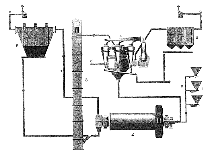
Cooling in the cyclone air separator
Cooling is performed by intake of fresh air. From. the exhaust duct of the blower, one part of the separator’s circulating air is exhausted and diverted to the dust collector. Now, through a fresh air duct, the blower takes in ambient air (cooling air), thus replenishing the deficiency of circulating air volume; by these means, the separator works with the full circulating air volume, required for separation (see Fig. 15.8.).
Separator with external blower; construction of SKET/ZAB, Dessau, D.R.
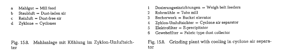
Since several years the SKET/ZAB Co. in Dessau manufactures a separator, which combines in one working unit the advantages of a speed controlled air separator with the principle of instrumental splitting of the separation and precipitation process (Fig. 15.9.). This separator shows substantially the same features as the cyclone separator described above.
Also here, the separating air is generated by a blower, located outside the separator housing. In the upper stage of the separating zone, the separating air, laden with fine particles, is drawn through radially arranged high efficiency cyclones, and cleaned. Since the separating air can pass the separating zone either as circulating or as passing air, this separator can be used for drying as well as for cooling purposes.
This separator is suitable for separation of raw mix as well as of cement. When separating different kinds of cements, the volume of separating air generated by the external blower, can be varied within wide limits. Standard quality cements with low Blaine numbers are manufactured with a low volume of separating air, and with low revolutions of the auxiliary fan. On the other hand, high quality cements with high Blaine numbers, require large volumes of separating air and high revolutions of the auxiliary fan. Besides, the classifying ability of the separator can be fundamen tally improved, by increasing the volume of the separating air. Throttling by the auxiliary fan does not occur. Depending on the separating air volume, all construction sizes show a pressure drop of 7- 9.5″ WG. About 50 % of the pressure drop is caused by the cyclone precipitators. Table 15.6.3. shows con struction sizes and capacities of separators with external blowers.
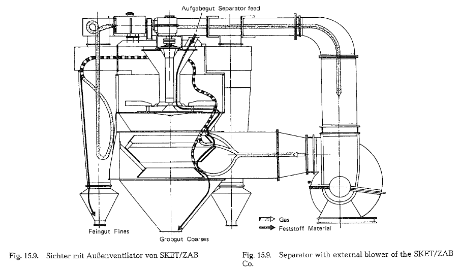
the external blower, can be varied within wide limits. Standard quality cements with low Blaine numbers are manufactured with a low volume of separating air, and with low revolutions of the auxiliary fan. On the other hand, high quality cements with high Blaine numbers, require large volumes of separating air and high revolutions of the auxiliary fan. Besides, the classifying ability of the separator can be fundamen tally improved, by increasing the volume of the separating air. Throttling by the auxiliary fan does not occur. Depending on the separating air volume, all construction sizes show a pressure drop of 7- 9.5″ WG. About 50 % of the pressure drop is caused by the cyclone precipitators. Table 15.6.3. shows con struction sizes and capacities of separators with external blowers.
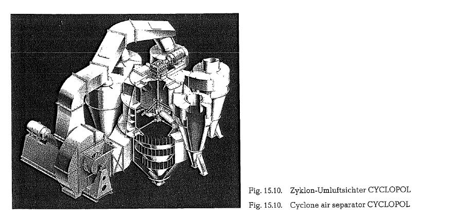
Cyclone air separator CYCLOPOL (Krupp Polysius AG)
The cyclone air separator CYCLOPOL also manufac tured by Krupp Polysius is, according to the manufac turer, preferably installed nowadays for the produc tion of raw mix and cements with a wide range of fine particle sizes (see Fig. 15.10.). The largest unit of the this type supplied so far is working in a plant with a throughput of 210 t/h.
The material is introduced laterally into the separator by an airslide and is uniformly distributed in the separating chamber by the distribution plate. An externally mounted blower produces the air stream, which flows through the material in the separating zone, classifying the material into coarse and fine par ticles by the effects of gravity and the air current. The fines entrained in the air current are precipitated in cyclones, which are equipped with air seals. The dust-free air is returned to the blower and reenters the separator through adjustable rings of guide vanes. This incoming air flows through the coarse particles as they trickle down over a series of baffles, thus exerting a secondary separation effect. The fineness and granulometric composition of the finished prod uct can be infinitely regulated over a wide range during operation of the separator by changing the speed of the distributing plates, return air vanes, and adjusting the flow rate of the separating air current. The CYCLOPOL separator is delivered with wear resistant linings, equipment for drying and cooling the material and continuous control of product fine ness from 2000 to 6000 cm2/g according to Blaine.
The separating zone has a higher loading capacity than that of the TURBOPOL separator. Because the finished product is separated in the external cyclones the specific power consumption of the CYCLOPOL is approx. 0.5 kWh/t cement (referred to 3000 cm2/g Blaine) higher than that of the TURBOPOL [159b]. However, the manufacturer states that cement grind ing systems equipped with the CYCLOPOL separator have, thanks to the better selectivity of this type of separator, a 10% to 30 % lower specific power con sumption (kWh/t cement) than systems equipped with a turbo separator.
The CYCLOPOL with its cyclones in a normal config uration requires hardly any additional space than the turbo separator. It is also possible to arrange the posi tions of the cyclones to fit local space conditions as well as to remove them completely. In this case, the total separator air is cleaned in an adequately large filter.
The configuration without cyclones is attractive when space restrictions are present or when the cement is to be cooled with fresh air. In addition, this arrangement results in a better separator efficiency due to clean and cool separating air. A possibility also exists to send the mill exhaust gas directly to the separator and clean both the mill and separator exhaust air in one dust collector.
In most cement works, the criteria used for assessing cement quality are the specific surface determined by the Blaine method and the percentage retained on the 30- or 32-micron sieve respectively. In Fig. 15.11. therefore, the specific surface values have been plot ted against the 30-micron sieve residues of cements produced by a large number of air separator grinding plants built by various manufacturers.
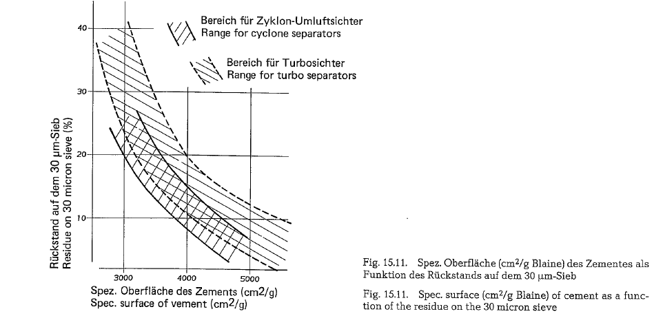
The cement finenesses produced in plants equipped with turbo separators normally lie in the area between the dotted curves. The area between the solid curves characterizes the product of plants oper ating with cyclone separators. Although the two areas overlap considerably, there is a distinct trend towards lower sieve residue values for cements prod uced with cyclone separators. For instance at a spe cific surface of 3500 cm2/g according to Blaine, the sieve residues for the turbo separator are in the range of 16-30 %, while the cyclone separator attains val ues in the range of 12-22 %. However, it also emerges that a well adjusted turbo separator plant can attain equally good results as a poorly adjusted cyclone separator arrangement.
Nowadays, when distinguishing between cements with the same specific surface values, the higher quality ratings are given to those cements which dis play lower sieve residues on the 30 micron sieve.
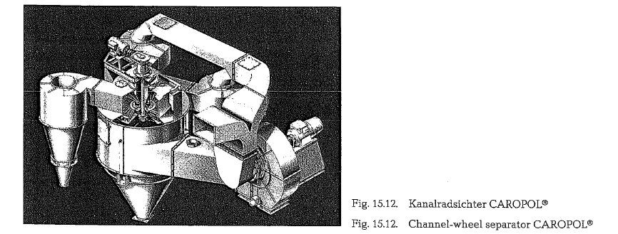
Channel-wheel separator with external blower (Krupp Polysius AG)
For several years, Krupp Polysius AG has manufac tured the channel-wheel separator CAROPOL. This separator (see Fig. 15.12.) is suitable for attaining high product finenesses and consists of the casing with its internal machinery, the cyclones mounted around it, and the external blower. The central feature of the internal machinery is the horizontal channel wheel. Essentially, this comprises a large number of rectan gular channels mounted on a circular plate. Behind each channel is a space through which the air current flows.
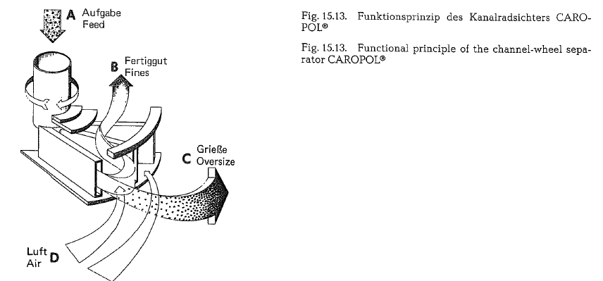
The feed material (see Fig. 15.13.) enters from the top through a tube which delivers it to the center of the wheel. It is then distributed by a cone to the indivi dual channels. The forces exerted on the particles by the rotation of the wheel cause them to spread in an even layer over the full surface of the rear walls of the channels, in relation to the direction of rotation.
The material streams as a uniform film over the out most edge of the channel and into the separating zone. The air current flowing through this zone sweeps the fine particles radially inwards through the air boxes. The coarse particles, which are less deflected by the air stream, are tossed against the casing and cascade down as tailings. The fines are precipitated in the external cyclones. The fineness and granulometric composition of the product can be controlled over a very wide range, as the manufac turer states even up to 10,000 cm2/g according to Blaine, primarily by adjusting the rotational speed of the channel wheel and secondarily by regulation of the airflow rate.
0-Sepa air separator (Fuller Co.)
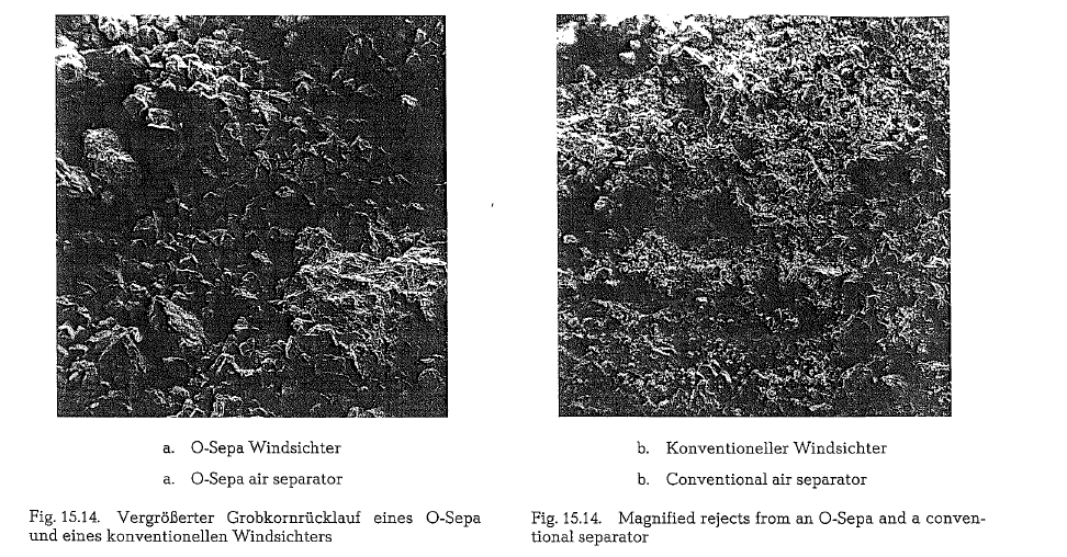
This newly (1983) developed air classifier (developed by and under license from Onoda Cement Co. Ltd., Tokyo, Japan) provides sharp classification and mill system energy savings. The efficiency of 0-Sepa can be illustrated by examining rejects and comparing them to rejects of a conventional air separator. The· fines in the rejects from a conventional separator contribute to mill inefficiency (see Fig. 15.14. a. and b.).
The pictures show that with 0-Sepa most fines have been classified as product, whereas the conventional separator has returned them for further grinding. This attests to the greater efficiency of the 0-Sepa separator.
The material fed to the 0-Sepa is directed onto the dispersion plate located on the top of the rotor by the feed chutes. It is then distributed by centrifugal force into the annular gap between the rotor and the guide vanes, the buffer plate providing an impact ring to direct the material down into the separation zone. The product is carried by the air flow through the separator into the center of the rotor, and exits the separator through the outlet duct located on the top with a right angle bend. The rejects are collected in the hopper and are discharged through the flap valve on the bottom.
There are three locations for gas flow to enter the 0-Sepa (see Fig. 15.15.).
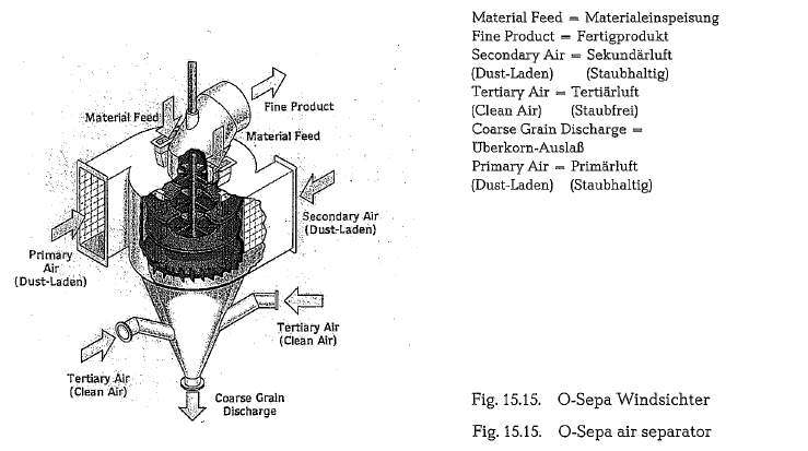
Primary air is comprised of mill vent air and ambient air entering through a bleed air damper. Secondary air is comprised of vent air from auxiliary equipment in the grinding circuit and ambient air entering also through a bleed air damper. Primary and secondary air both enter tangentially into the upper housing of the 0-Sepa. Tertiary air is all ambient air and enters the hopper through inlet ducts with dampers.
The primary and secondary air create a vortex in the separation zone of the separator, which is further enhanced by the stationary guide vanes located around the rotor. The rotor is comprised of horizontal partition plates which ensure a precise horizontal vortex is formed, and vortical flow adjusting blades which provide the final classification of the product. Initial classification is done by the vortex formed in the classification zone. Additionally, fine particles which are discharged into the hopper are also classi fied by the tertiary air which provides counterflow in the hopper.
The rotor speed can be adjusted by means of the vari able speed drive motor to allow adjustment of the required product size.
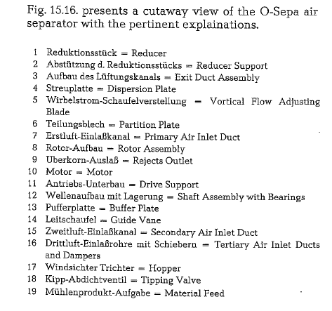
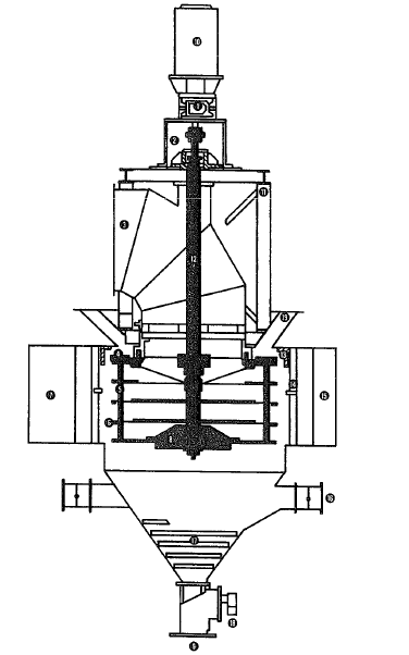
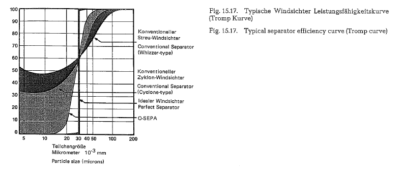
Fig. 15.17. shows typical separator efficiency curves. In the domain of classification of fine and coarse par ticles, these curves are also called Tromp Curves.
As indicated by these curves, 0-Sepa properly classi fies a higher proportion of feed particles into product and rejects, whereas conventional separators bypass a large percentage of acceptable product for regrinding, and coarse particles to product.
According to the manufacturer, the 0-Sepa separator shows the following advantages:
- Reduces power costs by up to 30 % while achiev ing better grinding efficiency through narrow par ticle size distribution of the end product.
- Reduces capital expenditures by increasing capa city up to 50 % for a given mill
- Adjusts easily for product fineness by means of a variable speed rotor
- Reduces auxiliary equipment requirements; only one vent and transportation system is required.Saves space by being only 1/z to 1/6 the size of con ventional separators.
- Adapts economically to existing circuits; 0-Sepa can service multiple mills [159 c].
Sepax®-air separator (F. L. Smidth)
This separator is of the single rotor type and was developed by F. L. Smidth with the specific aim of designing a simple, compact, and highly efficient unit, capable of handling the high outputs from large cement mills used today.
The Sepax is available in 12 sizes with diameters ranging from 2.5 to 4.75 m and installed motor power between 8.5 to 69 kW for capacities from 50 to 250 tph of finished cement with a Blaine surface of 300m2/kg.
The Blaine surface can be adjusted from 250 to 500m2/kg merely by changing the rotor speed.
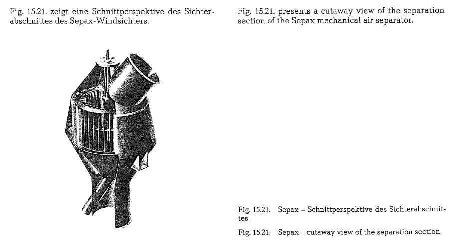
A special feature of the Sepax is the feeding of mate rial from the mill into an upward flow of air in a verti cal riser duct below the separator proper (see Fig. 15.18.). This results in thorough dispersion of the material prior to the separating process, a prerequi site for high efficiency, with the inherent advantage of separate discharge of broken and worn grinding media which fall through the air stream. This reduces the clogging tendency in mill partition grates. Com pared with conventional types of separators, the special Sepax feed arrangement reduces the height of the elevator which conveys the material from the mill outlet.
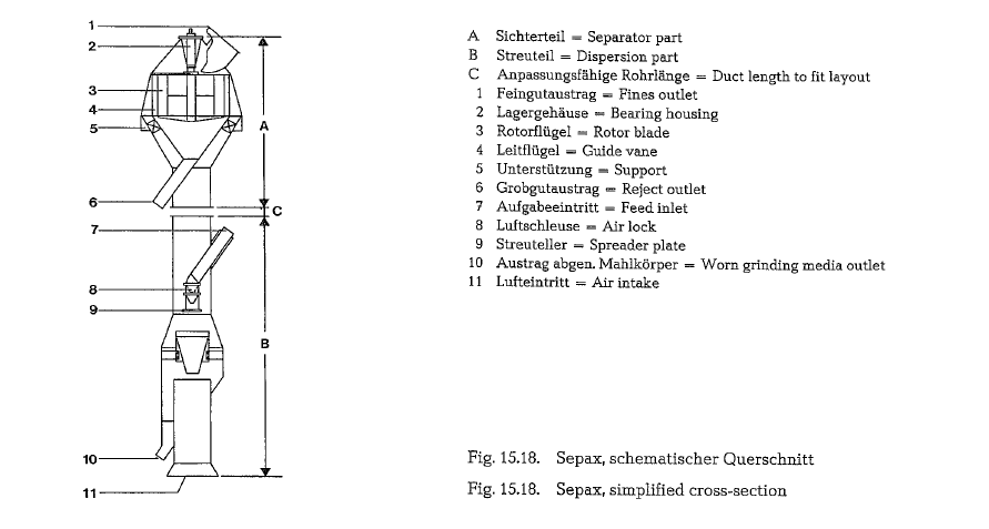
The suspended material flows into the separator via vertical guide vanes which maintain the even air velocity distribution. The guide vanes also function as collecting plates for the coarse material rejected from the rotor, the coarse fraction falling into a reject cone from where it is discharged via a sluice. Having passed the rotor, the finished material leaves the separator with the flow of air, and is collected in cyclones or in a bag filter.
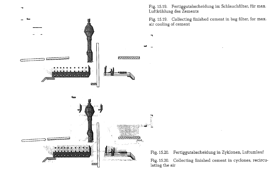
The air entering the bottom of the Sepax may be fresh or dust-laden, thus permitting any degree of recirculation. When fresh air is used (see Fig. 15.19.), the fines and tailings are cooled down to 70 to 75°C. thereby reducing mill cooling requirements. With moist additives in the mill feed such as slag or fly ash, full air circulation resulting in a tailings temperature of 110 to 120°C is usually preferred, a typical arrange ment of this description being shown in Fig. 15.20.
The complete dispersion of material in the riser duct, combined with uniform distribution of air, and mate rial along the full height of the rotor, not only explains the high efficiency of the Sepax but also its low degree of wear on separator internals. To ensure an even longer lifetime, the areas most exposed to wear are provided with renewable wear protection.
Separator capacity and cement fineness
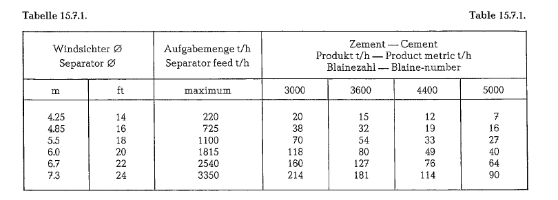
With increasing fineness of the cement, i. e. with increasing Blaine-number, the capacity of the separa tor decreases as shown in table 15.7.1. (Sturtevant Mill Company, Boston, Massachussets).
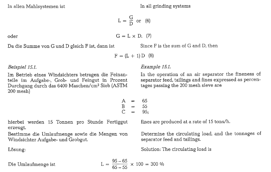
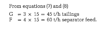
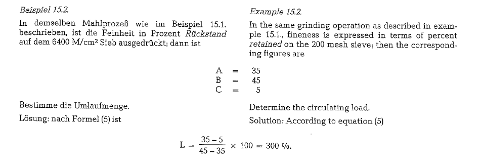
Air separator formulas
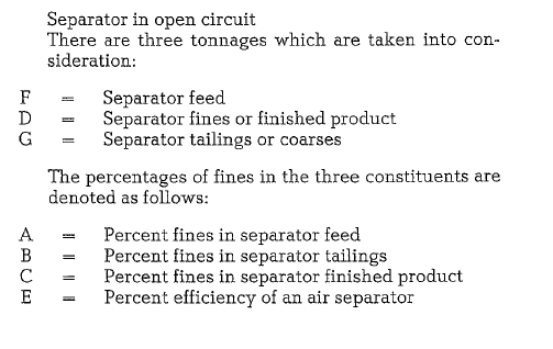
It is also evident that the total amount of fines going into the separator must equal the total amount com ing out of the separator. The total input of fines is then represented by the expression AF, the fines in the finished product by CD and the fines in the tail ings by BG. Without mathematical development given here [160, 160a, 160b] the final formulas are pre sented as follows:
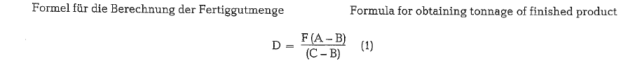
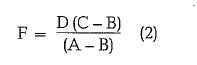
Knowing the value for F and determining the values for A, B and C, by sampling and screening, it is then possible to calculate the tonnage of the finished prod uct D.
Transposing formula (1), one gets the formula for obtaining the tonnage of the total load to the separa tor
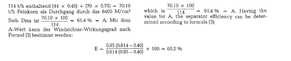
The efficiency of an air separator is expressed as the ratio between the amount of fines recovered in the finished product and the amount of fines introduced into the separator.
Formula for separator efficiency; this formula is also applicable to separators working in closed circuits of different circuit arrangements:
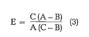
Consequently, separator efficiency may be deter mined by screening samples of separator feed, tail ings and finished product without regard to tonnage.
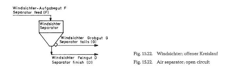
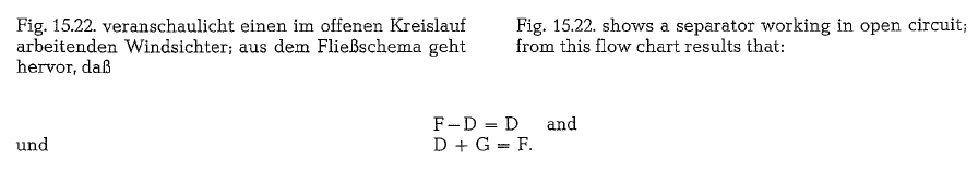
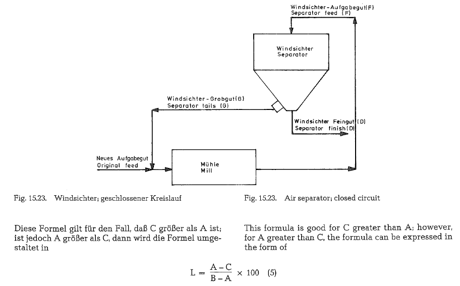
Closed circuit, system N° 1
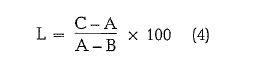
Fig. 15.23. shows a flow diagram in which the mill precedes the air separator so that the original feed enters the mill and is ground before classification. Here the tonnage of original feed equals the tonnage of finished product. In this case there is also a circu lating load to deal with. The circulating load (L) is the ratio of the quantity of separator tailings to the quantity of original feed.
Expressed in per cent it is called percent circulating load. If for example the ratio of tailings to fines is 2.50, then the circulating load is 250 ofo. The formula for circulating load in this system is
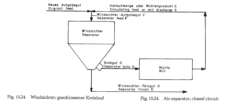
Closed cricuit, system N° 2
The flow chart in Fig. 15.24. shows that the air separa tor precedes the mill so that fine particles present in the original feed are discharged from the system without entering the mill. This system is employed in grinding operations where the main purpose is to eliminate oversize particles from the mill feed with out overgrinding the fines as e. g. when grinding cement raw mix.
As already stated, equation (4) for determination of the circulating load, applies to classifiers working in any circuit and consequently also to closed circuit system N° 2.
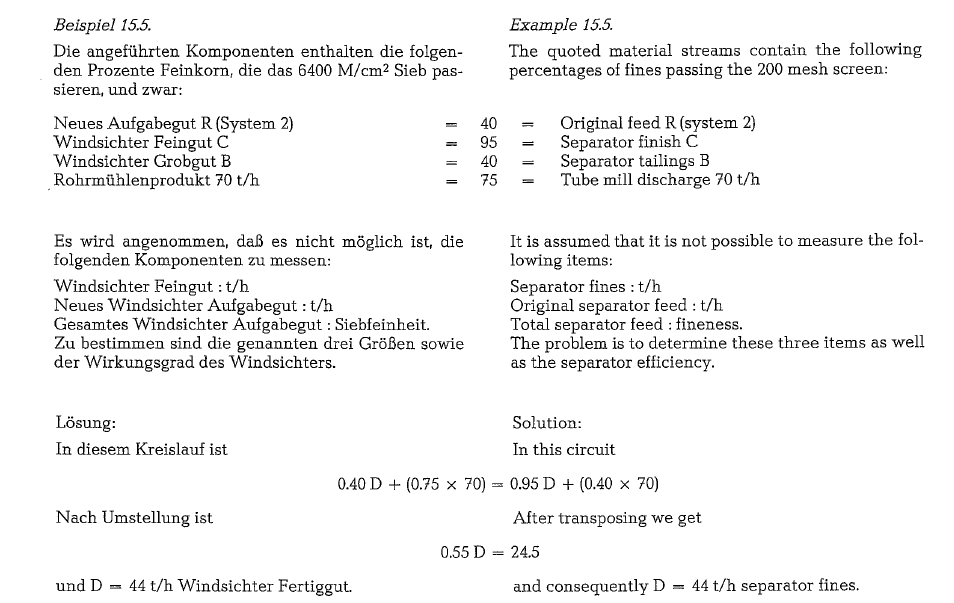
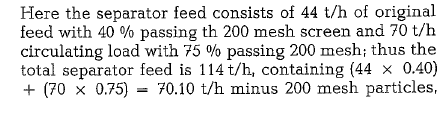
However, in some installations it is impossible to sample the classifier feed, so that the information required in equation (4) is not available. In such cases the circulating load may be calculated by the follow ing formula
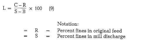
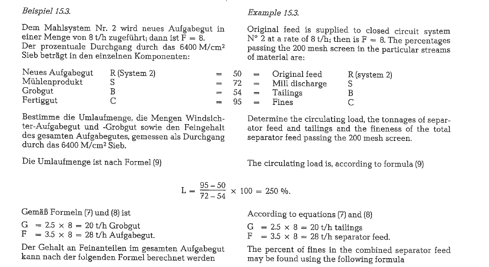
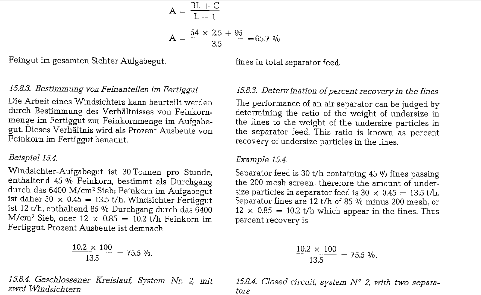
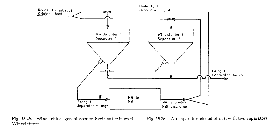
Fig. 15.25. shows a grinding circuit with one tube mill and two separators working in parallel. This circuit is basically the same as shown in Fig. 15.24. (closed cir cuit, system N° 2).
Quantity of classifying air
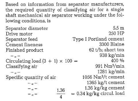
This ratio of air quantity to the quantity of separator material is a number applied in separator practice and explained in “Investigations Concerning the Car rying Capacity of Classifying Air Practical experience shows that a successful classifi cation of fine particle size material is attainable only at a certain content of material in the classifying air; this means that the quantity ratio of the separator material to the separator air must not be exceeded. Exceeding this ratio by overcharging the separator g. by increasing the circulating load, causes considerable reduction of classification rate, leaving a superabundance of fine particles in the separator tail ings. As in pneumatic conveying, the carrying capa city of air is not unlimited.
Above all, the point is to obtain an ideally uniform distribution of the separator feed over the cross-sec tional area of the separating zone. This is the reason for the various designs of feeding and dispersion arrangements for the separator feed.
IF YOU LIKE OUR POSTS AND WANT TO DOWNLOAD ALL OF THEM OFFLINE & IF YOU ARE INTERESTED IN DOWNLOADING THE MOST IMPORTANT BOOKS IN CEMENT INDUSTRY + ALL THE FORMULAS AND EQUATIONS AND CALCULATIONS SHEETS CLICK HERE TO DOWNLOAD THEM