Contents
Roller mills
IF YOU LIKE OUR POSTS AND WANT TO DOWNLOAD ALL OF THEM OFFLINE & IF YOU ARE INTERESTED IN DOWNLOADING THE MOST IMPORTANT BOOKS IN CEMENT INDUSTRY + ALL THE FORMULAS AND EQUATIONS AND CALCULATIONS SHEETS CLICK HERE TO DOWNLOAD THEM
As a result of the development of suspension preheater kilns, and of a variety of high wear resistant steels, fast running mills are becoming increasingly popular with the cement industry. The number of roller mills employed in the cement industry shows an upward trend [142].
Roller mills have a lower specific energy consumption than tumbling mills, and require less space per unit and capacity at substantial lower investment costs. Roller mills are developed to work as air-swept grinding mills. With built-in air separators these mills grind in closed circuit, almost always as drying-grinding mills.
Roller mills are now operated with throughput capacities of more than 500 tons per hour of cement raw mix (Loesche-mill, Polysius double roller mill, Pfeif fer-MPS-mill, SKET/ZAB-roller mill).
The working principle of roller mills is based on two to four grinding rollers with shafts carried on hinged arms and riding on a horizontal grinding table or grinding bowl. In smaller mills the pressure of the grinding rollers was effected by helical steel springs, connecting the hinged arms (spring type roller mills), whereas in larger mills the grinding pressure of the rollers upon the mill feed is effected hydropneumatically.
Loesche roller mill (Loesche GmbH, Dusseldorf, -Germany)
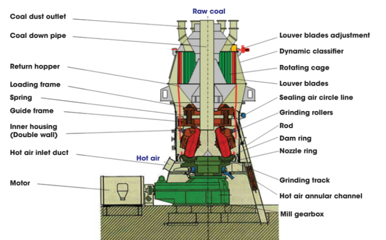
Fig. 13.1. shows a cross-section of a Loesche-mill with a conical rotor type classifier. The pressure arrange ment of the grinding rolls upon the mill feed in the grinding bowl is hydropneumatically [144].
The mill feed is introduced into the mill from above, falling centrally upon the grinding table; then it is thrown by centrifugal force underneath the grinding rollers. A retention ring on the periphery of the grinding table forms the mill feed into a layer, called the grinding bed. The ground material spills over the rim of the retention ring. Here an uprising air stream (generated by a special fan), lifts the material to the rotor type classifier located at the top of the mill cas ing where the coarse particles are separated from the fines. The coarses drop back into the center of the grinding compartment for further size reduction whereas the fines together with the mill air leave the mill and the separator. The separator is an air-stream gyroscopic classifier which is installed directly on the mill [145].
The gyroscopic classifier controls product sizes from 600 to 40 microns. It consists of a truncated conical rotor, with a series of vertical bars attached to the cir cumference. Around this rotor is a conical housing for confining and directing air currents upward. The rotor revolves on a vertical shaft at relatively slow speeds and imparts a centrifugal motion to the mater ial-laden air current, deflecting the coarser particles out of the air stream against the conical housing, where the particles slide into the mill for further grinding. The fine product moves out of the separator with the air discharge. The gyroscopic classifier is partially shown in Fig. 13.1.
The vertical transportation of the ground material from the grinding table to the air separator through the use of a hot gas stream, makes the roller mill particularly suitable for simultaneous drying and grinding, especially since the circulating load totals 8 to 10 times the amount of the mill feed. Hot exit gases which are available in a cement plant can be used as the uplifting air stream for simultaneous drying.
Product fineness is controlled by varying the speed of the separator rotor.
The grinding parts of the roller mill, consisting of roller shells and of a segmental grinding ring, show a wear rate appropriate to the properties of the raw material. The wear parts require replacement after 1-2 years of operating time. According to the roller sizes, 2 -4 inches of the grinding parts can be used up, without a noticeable decrease in mill capacity. A hydraulic roller swing-out arrangement simplifies maintenance work, and allows for replacement of the wear parts within one day. Worn out roller rings should be replaced periodically. The wear rates when grinding cement raw material are for grinding parts as rollers and grinding ring about 3-5 grams/rot of ground material [146].
Range of application and power requirement
The maximum moisture of the mill feed (cement raw material) can amount to 20 %. Generally, the fineness of the mill product can be adjusted in the range between 94 and 80 % passing 170 mesh. Capacities of more than 500 t/h of cement raw mix are quoted.
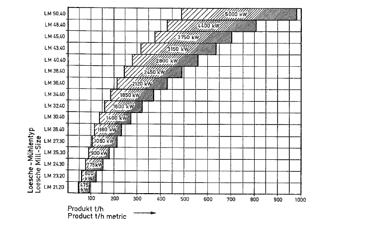
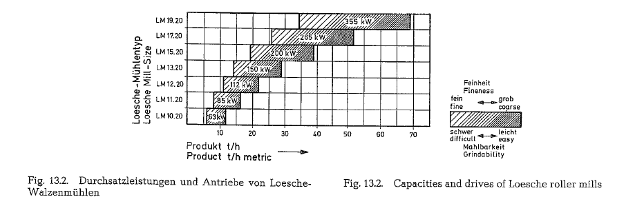
Fig. 13.2. shows a selection chart of Loesche-mills, outlining sizes, capacities and appropriate power requirements [147].
Operational results indicate a specific power requirement of 13 kWh/mt, measured on the electric meter, when grinding semi-hard cement raw material to a fineness expressed as 88 % passing the 170 mesh sieve (ASTM) and 99 % passing the 70 mesh sieve, at 8 % moisture of the mill feed. The energy require ment comprises the drives for the mill and separator, the mill feeder, mill blower, and the E-precipitator. Practically, the specific energy consumption is inde pendent on the mill’s size.
Generation of coal dust in central grinding plants which presently are mostly installed for firing of rotary kilns, requires an electrical energy consump tion of 20-24 kWh/mt, at a coal dust fineness expressed as 85- 90 % passing the 170 mesh sieve (ASTM). Additional energy is required for blowing the coal dust into the rotary kiln burner, or into the precalciner.
When sizing the mill blower it should be taken into consideration that the resistance of roller mills rises with increasing mill size. At the same grindability, and at the same particle size of the finished product, the resistance is in the range of 40- 90 mbar.
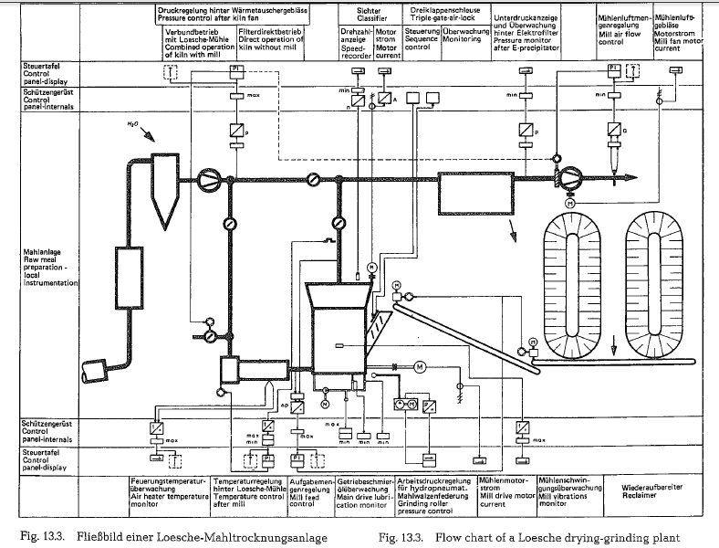
Fig. 13.3. shows a flow chart of a Loesche-mill for drying-grinding of cement raw material. applying exit gases from a preheater kiln. Besides regular operation, at which the kiln exit gases pass the mill, and, if necessary, are boosted by an air heater, this arrange ment allows the gases to bypass the mill, and to enter the dust collector, after cooling in a spray tower. There are separate control loops for various operat ing conditions.
Ball race mill (Peters-mill of the Claudius Peters Joint Stock Company, Hamburg, Germany)
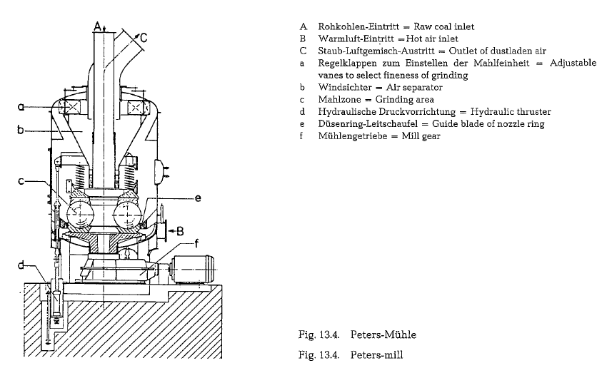
The cement industry employs the Peters-mill (pre viously called Fuller-Peters-mill) mostly for coal grinding. It is a few years now that the shockproof construction (shock resistance – 3.5 bar) of the Peters-mill was designed for coal grinding. Essen tially this mill consists of the grinding compartment, the separator, and the drive machinery. The grinding compartment is formed by the grinding rings, the lower one rotating and the upper one stationary. Adjustable steel springs or hydraulic as well as hydraulic-pneumatic pressure devices, press the upper grinding ring against the grinding balls which are set close to each other. The grinding balls roll between the rings as in a ball bearing.
A feeder introduces the mill feed either centrally through the mill classifier or laterally through the mill shell into the grinding compartment where cen trifugal force throws it underneath the grinding balls.
The ground material leaves the grinding set on the periphery; here an uprising air stream lifts the material to the separator. The classifier rejects return to the grinding compartment, whereas the fines leave the mill with the air.
Wet mill feed can be dried inside the mill by applying hot air or inert gases of proper temperature. According to manufacturer’s statements, inlet gas temperatures up to 400 °C are admissible with no special precautions.
The Peters-mill, Type EM is supplied with high wear resistant cast steel grinding balls which are manufactured as hollow spheres. Depending upon the mill size, ball diameters go as high as 1250 mm.
Fig. 13.4. shows a scheme of the shock-proof design of the Peters-mill.
Fig. 13.5. represents some of the most common system layouts of Claudius Peters coal grinding plants. Pic ture 1 shows a direct firing mill, picture 2 an indirect firing mill with partial flow of exhaust air being con veyed into the open air, picture 3 a central grinding plant with coal dust silo and Peters dust pump, gases from the heat exchanger or hot gas generators for the grinding-drying process.
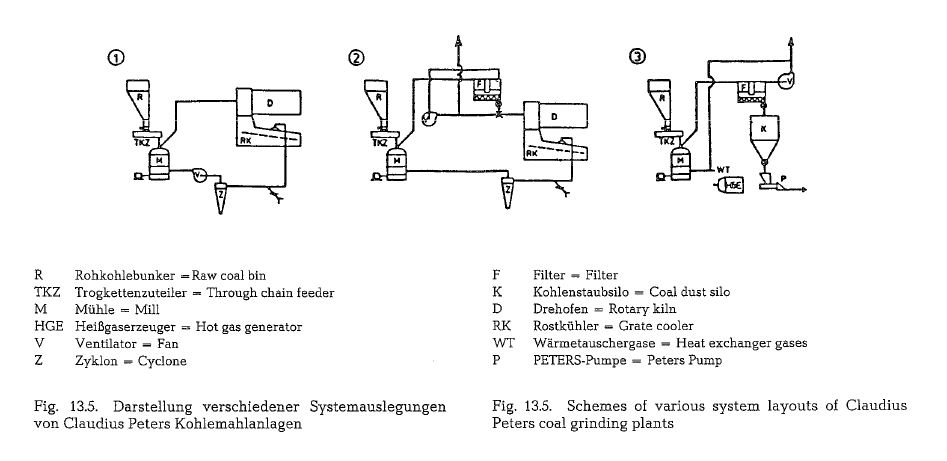
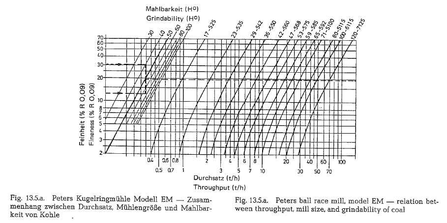
Fig. 13.5.a. shows the characteristic lines of the Peters ball race mills, Type EM for coal grinding. Through put in t/h depending on the grindability according to Hardgrove H0 , the grinding fineness expressed as % residue on the No. 170 sieve, and the mill size .
Raymond bowl type ring mill
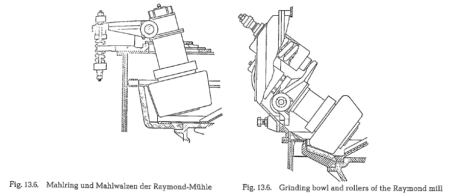
The Raymond bowl type ring mill [148] for coal drying-grinding is widely used in the American cement industry. This mill has all the characteristic features of the roller mills described above; it consists essentially of a replacable grinding ring, carried by a rotating grinding bowl. The grinding rollers are pressed by springs against the grinding ring. The ring rim speed of the grinding bowl is 5.3 to 6.5 m/s.
Fig. 13.6. shows portions of grinding bowl and rollers of Raymond bowl type ring mills. Fig. 13.6.a. is a direct grinding mill with suction firing; Fig. 13.6.b. is a direct grinding bowl type ring mill with pressurized firing. The different design of grinding bowl and rollers results from the deviating lines of the hot air at pres surized and suction firing respectively.
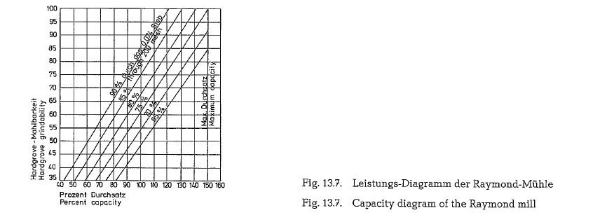
The Raymond-mill grinds in conjunction with an externally adjustable classifier which permits fine ness changes of 20 % to 30 % on the minus 200 mesh product, i. e. approximately 65 % to 90 % minus 200 mesh. The adjustment can be made with the mill in operation. The influence of the product fineness upon the capacity of the Raymond-mill is diagrammatically shown below in Fig. 13.7.
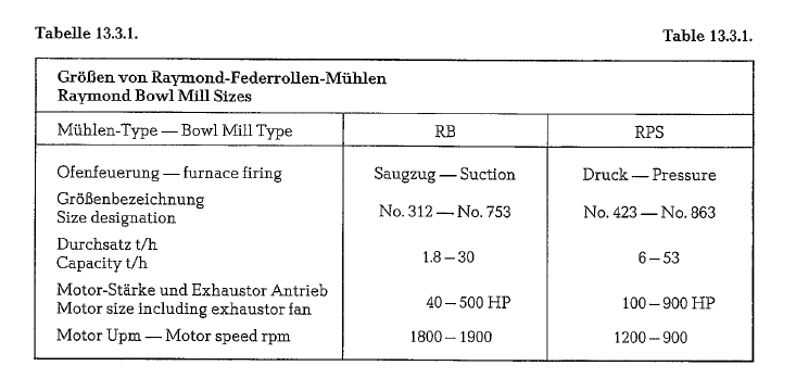
Capacity ranges and sizes of Raymond bowl type ring mills are shown in table 13.3.1. Capacities are based on the use of coal with number 55 of the Hardgrove grindability index; the coal being pulverized to 70 % passing 200 mesh; original moisture of coal is 12 %. This table contains information on only the smallest and largest sizes of Raymond mills.
MPS roller bowl mill (Gebr. Pfeiffer Co., Kaiserslautern, W.-Germany)
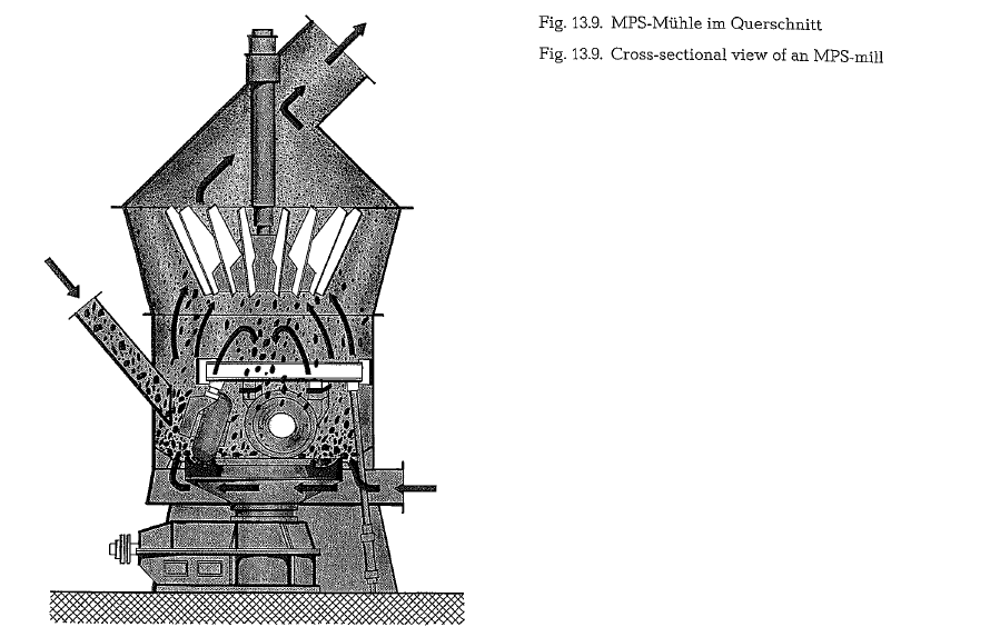
The structure of the MPS-mill is essentially similar to that of the other roller or bowl mills. However, instead of two stationary grinding rollers the MPS mill has three, which ride on a rotating grinding bowl. A hydraulic-pneumatically prestressed spring system acting simultaneously on all three rollers, produces the necessary grinding pressure. The grinding-drying system of this mill is based on the airstream principle, as shown schematically in Fig. 13.8.
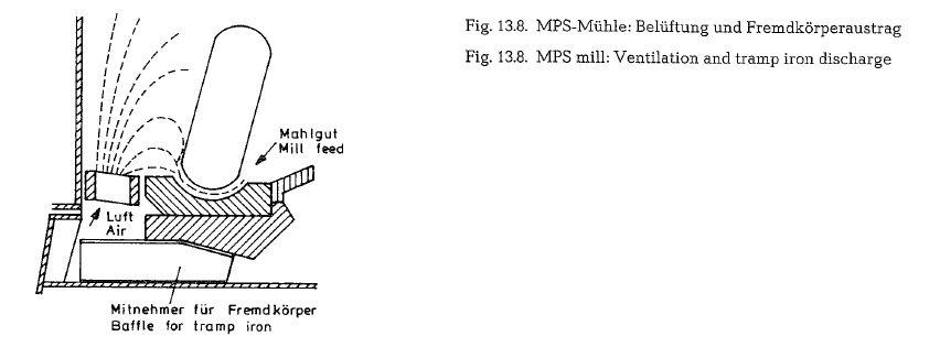
The drying gases entering the mill casing through a ring of nozzles arranged around the grinding bowl, raise the mill feed up to the separator, drying the feed simultaneously. Any tramp iron there falls down through the air nozzles, and is discharged out of the mill.
This design of the Pfeiffer MPS-mill shows in the area of the grinding tools a relatively large free cross-sec tion. This results in an adequate lower pressure drop in the mill. On the other side, this arrangement allows for a higher utilization of low heat energy kiln exit gases for the drying process.
When operating a Pfeiffer MPS-mill with an addi tional air heater, e.g. a drying effect from an initial moisture of 18 % to a residual moisture of 0.7 % was attained. The inlet temperature of the hot gas into the mill was about 450 o C, and the exit temperature from the separator was about 105 oc.
Fig. 13.9. shows the cross-sectional view of an MPS mill.
In the cement industry, the MPS mill is used for drying-grinding of raw material and coal as well as for cement grinding. It is available in many sizes ranging from very small throughput rates up to 500 t/h. From the approximate 1,500 MPS mills supplied so far (up to 1985), 120 mostly large units are used for raw material grinding whereas 1,250 mills are grind ing coal in power plants and for cement rotary kilns.
The energy requirement for the drying-grinding pro cedure of raw material is quoted to be 9 kWh/metric ton (12 HPh/t), whereas 5.8 kWh/t (7.8 HPh/t) is required for the sole grinding to a fineness expressed as 82 % passing the 170 mesh sieve. The difference between 9 and 5.8 kWh = 3.2 kWh/t (4.2 HPh/t) is apportioned to handle the pressure drop in the mill which is approximately 360 mm W.G
At mill sizes employed most frequently, the diame ters of the grinding rollers are in the range of 1400- 2500 mm. When grinding coal, the net wear of the grinding rollers is 12 g/t of mill feed. Grinding rollers as well as the grinding bowl are of Ni-Hard material, with a HV(Vickers) hardness of 650.
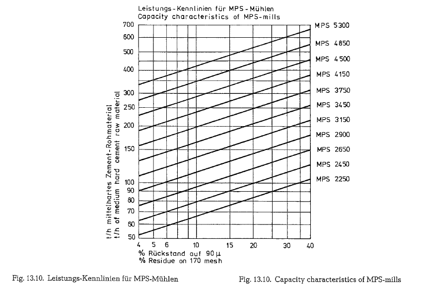
Fig. 13.10. shows capacity characteristics and con struction sizes of MPS-mills. The lines shown in the diagram are valid for medium hard cement raw material. Depending on the hardness of the raw material, the feed particle size for roller mills can amount to about 10% of the grinding roller diameter. For this reason, when compared to a ball mill, the roller mill does not need a precrushing stage.
Of course, the wear of grinding parts of MPS-mills depends also upon the properties of the ground material. For soft cement raw material the wear rate is about 0.1 grams/t (metric); however, in extreme cases, the wear rate can increase up to about 15 grams/t. The wear parts of the grinding bowl, as well as of the rollers consist of segments, which can be easily replaced.
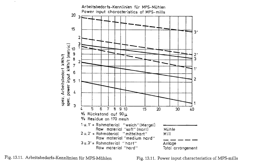
Fig. 13.11. shows power input characteristics of MPS mills, for three different kinds of raw material, with a fineness of the ground product in the range of 4-40% residue on the No. 170 mesh sieve.
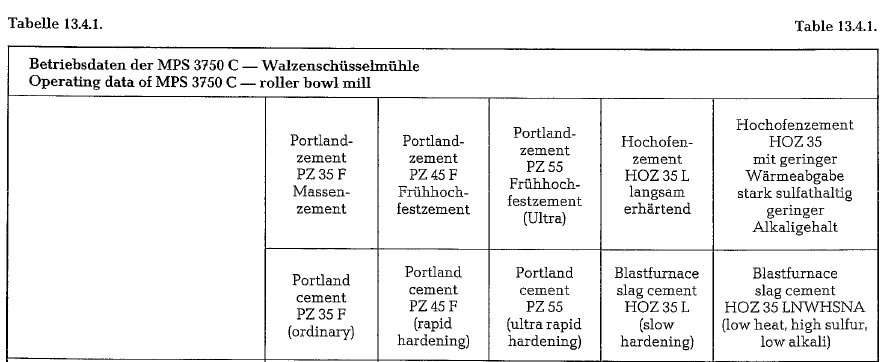
In 1980, the first large-scale vertical roller mill of the type MPS 3750 C for the grinding of Portland cement and slag cement was commissioned in a German cement plant. The results of permanent operation so far reveal that energy savings are as much as 30 % compared to the ball mill. All cements from standard to ultra-rapid hardening cement as well as slag cements with up to 78 % of slag content can be ground with the most favorable setting for each duty. Slag cements are simultaneously dried and ground in the mill with very low heat requirement. The finished product leaves the mill at low temperature, so that extra cooling by water injection or coolers is not necessary.
Costs of wear, maintenance and overhaul do not exceed those of the ball mills. The grinding elements are made of wear resistant material giving long life time. The production is very uniform in fineness and quality.
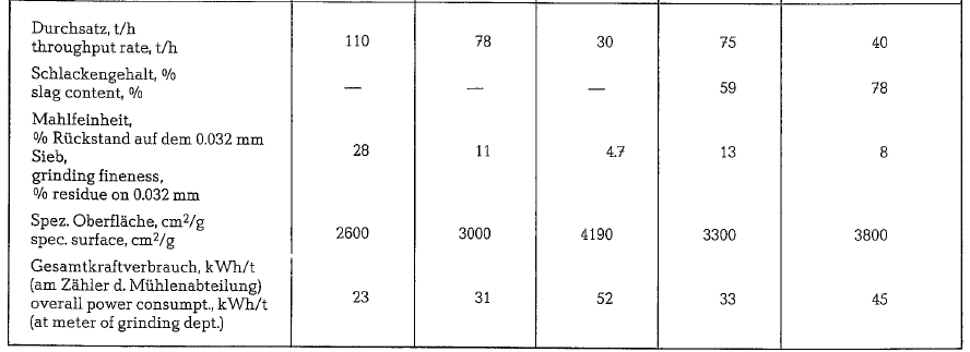
In Table 13.4.1. throughputs of the MPS 3750 C roller mill are given. Operating data quoted above are based on manufacturer·s information
Polysius roller mill
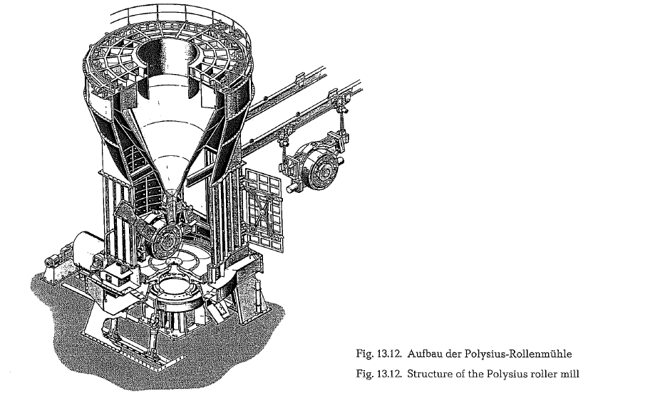
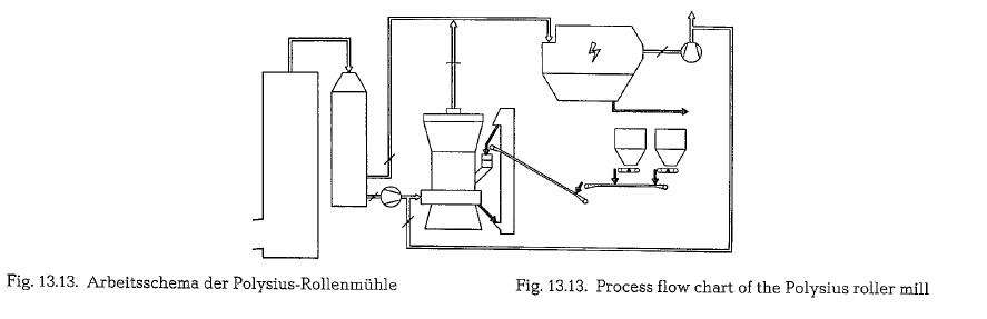
Fig. 13.12. and 13.13 show the structure and the pro cess flow chart of the Polysius drying-grinding roller mill.
The following dimensions and operational data are quoted for a Polysius roller mill with a capacity of 270 short t/h of dry raw mix [148a4].
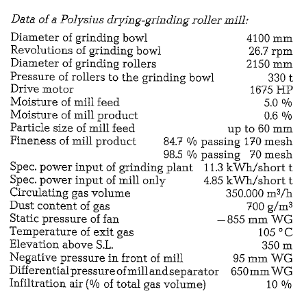
The total exit gas volume from a suspension prehea ter kiln is utilized for drying of the quoted quantity of the raw mix. The above figures show that a considera ble part of the power input is absorbed by the ID-fan. Compared to the raw grinding tube mills working in the same cement plant, the roller mill arrangement is quoted to show a saving of roughly 13 %
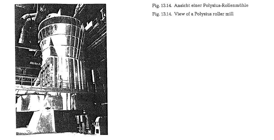
Fig. 13.14. shows the view of a Polysius roller mill.
A raw material moisture of up to 8% can be dried, when utilizing the suspension preheater exit gases only. If hot air from an air heater is also supplied, then a raw material moisture of up to 30 % can be handled
For some time past (1974), Krupp Polysius AG started a development program with the aim of extending the use of the roller mill from its proven field of raw material grinding into the clinker grinding sector.
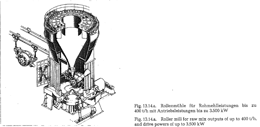
The essential design features of the raw-material roller mill were retained. Continuous optimization had led to the development of the mill illustrated as perspective view in Fig. 13.14.a. This version is designed for outputs of raw mix up to 400 t/h and drive powers of up to 3.500 kW.
The principal components of the mill are the motor, which drives the grinding table via, for instance, a bevel planetary reduction gear; the grinding table mounted in tilting-pad thrust bearings; the two pairs of rollers; the mill housing and the stationary separa tor equipped with adjustable guide vanes.
This roller mill shows the following design alterations in comparison with that of a raw material roller mill:
- Instead of the single groove of the original ver sion, the grinding ring has for this purpose a dou ble groove, in order to lengthen the material retention time on the grinding table and to improve the degree of comminution achieved before the material leaves the
- Both rollers have the same shape and the diame ters of the tires are smaller than those of the
- The wearing parts (grinding table liners and roller tires) can be made of Ni-Hard IV or chrome alloyed chilled cast The roller tires can optionally consist of one-piece or of segments.
- The nozzle ring, through which the gas stream enters the grinding can be adjusted from outside while the mill is running, to regulate the nozzle openings and thus set the optimum gas velocity for conveying and pre-classifying the material leaving the grinding table.
- Ceramic tiles are used for the wearing lining of the housing and other parts exposed to abrasive jet
- Instead of the stationary separator, an indepen dently driven dynamic separator can be mounted on the mill
Fig. 13.14.b. shows the design features of a roller mill plant for cement grinding. The material falls onto the center of the grinding table; when it leaves the grind ing table it is entrained in the stream of air and car ried to the separator. The classified coarses are then returned directly onto the grinding bowl. Cyclones are used to collect the finished product carried out of the separator in the stream of air. Most of the air is returned to the mill, while a small portion is carried to the dust collector.
As less energy is expended in the roller mill itself than in a ball mill, less heat is produced by the grind ing process. The problems involved in dissipating heat are simpler to solve, especially since the large quantity of air required for conveying the material in the mill can also be used for cooling.
This large quantity of air is also advantageous when drying moist slag in the mill. as the inlet temperature can be kept low, thus preventing problems arising with dewatering the gypsum.
The velocity of the air passing through the ring of nozzles is so selected that larger particles of clinker fall through and are then returned to the mill by a small bucket elevator.
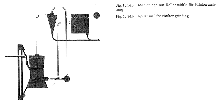
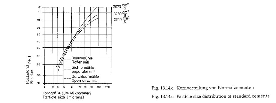
Fig.13.14.c. shows the particle size distribution curves of three standard cements produced by the Krupp Polysius roller mill, a closed-circuit ball mill (air separator mill) with a throughput of 120 t/hour, and an open-circuit ball mill with a throughput of 150 t/hour. The curve for the roller mill cement corres ponds fairly closely to the other two curves in the fin est particle size range, but is distinctly steeper above 10-15 microns, i.e., this cement contains a lower pro portion of the coarser particles that adversely affect strength.
Strength development curves of the cements ground in the roller mill are presented in Fig. 13.14.d. for the three portland cement grades concerned. For compar ison the 2-day and 28-day strengths found as average values for the cements investgated by the VDZ (Asso ciation of German Cement Manufacturers) in 1977 are included. These last-mentioned cements were ground in ball mills.
It appears from this diagram that the strength development for all three roller mill cement types corresponds with that for the ball mill cements.
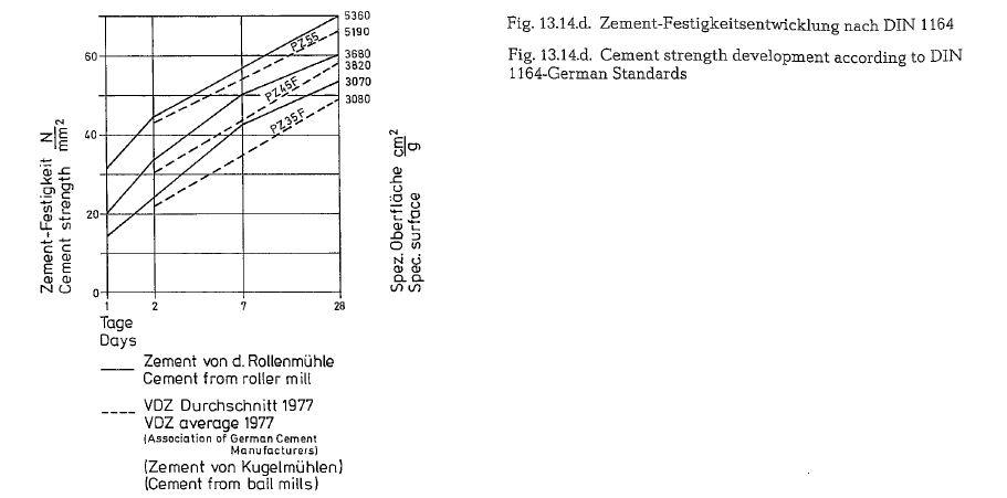
In many cases the roller mill has produced cements with low specific surfaces whose final strength values were superior to those of cements produced by ball mills. According to Krupp Polysius it has been found that, owing to their steeper particle size distribution, roller mill cements can have lower specific surfaces for particular final strength values than ball mill cements. Without exception, cements produced with the roller mill have a more favorable strength development than comparable cements with the same specific surface produced in ball mills. The results as a whole show this cement to be of good quality.
For a grinding plant designed for an output of 80 t of portland cement per hour a roller mill with a grinding bowl diameter of 4.1 m is required. The total power consumption of the grinding plant is 26.5 kWh/t, cor responding to a 20 % saving in comparison with a plant incorporating a ball mill. Apart from the mill itself, the largest energy consumer in the roller mill grinding plant is the circulating air blower, which has to be designed for a capacity of 240.000 m3/hour in the case envisaged here, while the exhaust air rate is 45.000 m3/hour, which is sufficient to discharge excess heat from the system without applying water injection. A ball mill for this throughput would have a diameter of 3.8 m, assuming it works in a closed-circuit system.
In order to assess the economy of the roller mill fin ish grinding process, it is necessary to determine the overall operating costs and compare these with the corresponding figures applicable to a ball mill grind ing process. In Table 13.5.1. the annual costs of cement grinding in the 80 t/hour ( = 400.000 t/year) plant envisaged here are compared with the figures for a ball mill operating in closed circuit with an air separator. The overall costs for the roller mill have been put at 100 %. The main advantage of roller mill grinding lies in the lower electric power consumption
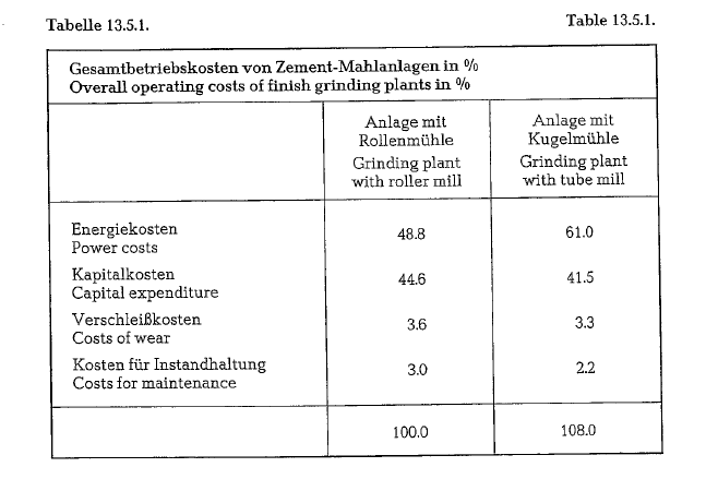
and correspondingly lower costs. For this mill an average specific power cost figure of 0.12 DM/kWh (DM =German Marks) has been adopted.
The capital cost figure is based on a ten-year linear write-off for depreciation, and the costs of borrowing have been taken into account. The calculation of the investment comprises the complete mechanical and electrical engineering equipment supplied, the erection of this equipment, and the costs of buildings. It emerges that the total capital costs of the ball mill plant are about 93 % of that of the roller mill plant.
The net rate of wear in the roller mill is only about half of what it is in the ball mill. However, in the roller mill there remains a larger non-utilizable resi due from the parts which undergo wear, while the specific costs of the wearing parts in DM/kg are higher, so that the overall costs in respect of wear are roughly the same for the two grinding systems.
The servicing maintenance costs include the normal amount of labor and the costs of spare parts. Labor includes the renewal of wearing parts, but not the capital expenditure in respect of holding stocks of spare parts available. This item of expenditure is higher for the roller mill. There are no labor costs for mill control, since both types of grinding plants are controlled from the central control room.
In this example the roller mill is about 8 % more favorable in respect of overall economy.
It is to be noted that the cost comparison given here has had to be based on certain assumptions which are not necessarily valid in every case. Hence a cost cal culation will have to be done in each individual case where a comparison is required.
The saving of 8 % in favor of the roller mill is based on a product fineness of 3000 cm2/g (Blaine) for both mill types. The cement from the roller mill has a somewhat higher strength. Basing the comparison on equal cement strength, a larger saving is obtained, because the throughput of the roller mill increases, i.e., the capital costs become lower, and furthermore also the specific power consumption is lower, i.e., power costs are likewise reduced.
Shut-off devices for gas ducts
Roller mills work almost exclusively as drying-grind ing millis. Because of economical reasons, these mills are fed with hot exit gases from rotary kilns or raw mix preheaters. The gas handling requires corres ponding large diameter ducts which, for control pur poses of the gas flow, are supplied with shut-off dam pers. A special construction of shut-off dampers applied widely in the cement industry, is the so-called sickle damper of the PKS Engineering GmbH and Co. Beckum, W. Germany (see Fig. 13.15.). Sickle dampers are manufactured for duct diameters in the range of 500- 4500 mm. This damper is applied in kiln exit gas ducts where waste heat is utilized; also in gas ducts in front and behind drying-grinding mills, and to shut-off electric precipitators; further in exit gas ducts of roller or bowl mills, whereby the dust content of the mill exit gas can amount up to 1000 grams/m3. This kind of damper is also used in hot air ducts, leading from the clinker cooler to the raw mix precalciners (so-called tertiary air ducts). Special construction permits this damper to apply in gas temperatures of up to 700 °C, and pressure of 500 mm WG. The sickle damper can be actuated pneumatically or hydraulically, with electrical remote control.
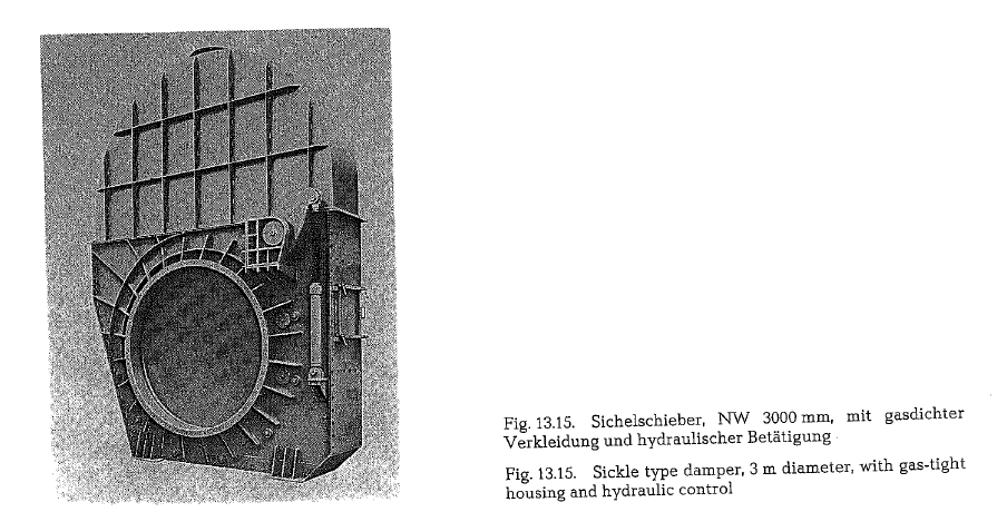
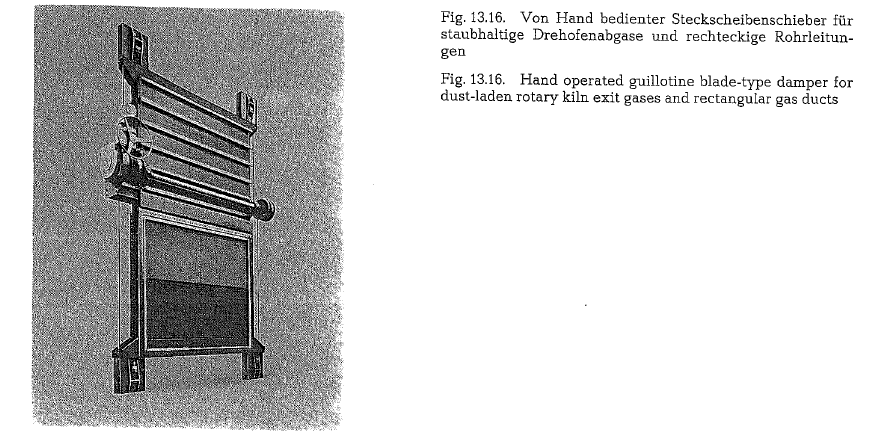
Fig. 13.16. shows a guillotine blade-type damper of the size 3600 x 3000 mm, for dust laden rotary kiln exit
gases to be used in temperatures up to 400 ac. The differential pressure can amount up to 1400 mm WG.
This damper is furnished with a central lubrication system, and is manufactured for square and rectangu lar ducts in sizes with a cross-section of up to 20m2.
This damper can be applied to all gas ducts of a cement plant; its main application is for shut-off of gas ducts for repair and maintenance of subsequently located machinery and equipment [148a.3.]. The man ually operated guillotine-type damper is used in locations where the cost of a remotely controlled damper is not justifiable .
IF YOU LIKE OUR POSTS AND WANT TO DOWNLOAD ALL OF THEM OFFLINE & IF YOU ARE INTERESTED IN DOWNLOADING THE MOST IMPORTANT BOOKS IN CEMENT INDUSTRY + ALL THE FORMULAS AND EQUATIONS AND CALCULATIONS SHEETS CLICK HERE TO DOWNLOAD THEM
much information, pretty good.