Contents
Grate Coolers
[wpecpp name=”package + Updates forever” price=”250″ align=”center”]
I. CLINKER FORMATION AND CLINKER GRANULOMETRY
It is a well-known fact that the granularity of clinker products can vary considerably from
one cement plant to another. Even kilns within the same plant are often found to produce
quite different clinker, although fed with the same raw mix.
FIGURE 1 shows some sieve test results obtained from a wide range of clinker samples. It
appears that the dust content, for example grains finer than half a 111m, can vary between I
and 70%. Also the presence of even a small proportion of oversize clinker, say bigger than
40mm (1-1/2″), contributes very much to the overall appearance of a clinker product.
Furthermore, clinker made up of compactly fused and well shaped nodules appears to be
completely different from clinker with a similar sieve curve, but consisting of cokelike and
sharp edged agglomerations of dust particles
.
Such observations have naturally led to investigations of the factors affecting clinker
formation.
In preheater kilns, the formation of nodule shaped clinker must take place in or just above
the burning zone, since the raw mix somewhere further up in the kiln is in the form ofmeal.
In a wet-process kiln strong nodules often come out from the chains as determined during the
drying of slurry. The extent to which these nodules affect the final clinker granulometry, if
at all, is unknown. However, wet kilns tend to produce a coarser clinker size distribution
than do precalciner kilns.
Clinker formation is related to raw mix composition and operating conditions. The clinker
formation may start already in the calcining zone, where a certain agglomeration ofthe fine,
solid particles may take place aided perhaps by the presence of low melting alkali salts.
However, the final result depends on what happens in the burning zone. Here the formation
of liquid phase begins at a temperature slightly below l300°C, and the quantity of liquid
increases with the temperature up to a certain final value as shown in FIGURE 2.
The amount of liquid does not increase gradually with the temperature, but in steps on
reaching certain temperatures. Only by applying extreme temperatures can this final amount
of liquid be further increased which, however, usually has disastrous effects on coating and
lining.
The quantity of liquid phase at normal burning temperature amounts to 20-25% of the
clinker, depending on the content of alumina, iron, magnesia, and alkalies. If the quantity of
liquid phase is too small, good clinker formation will not take place. Conditions may then
be improved by changing the raw mix composition, which in practice is usually done by
adding iron ore, thus reducing the silica ratio.
In some cases it will be possible to improve the clinker formation by burning harder, even
harder than required for bringing down free lime. The reason, of course, being an increase in
liquid phase. But it is often seen that if the burning temperature is raised even further, the
result will be dusty clinker, probably due to a too low viscosity of the liquid. At several
plants we have also found a rather sharp limit to the lime saturation factor, if good clinker
grading is to be obtained; if this limit is exceeded the clinker becomes dusty.
The clinker granulometry is important for the satisfactory operation ofany cooler: There
must not be too much dust. Less than J5% minus 0.5 mm (0.02″) is good. Too much clinker
plus 25 mm (I”) increases the clinker temperature after the cooler because of the slow
cooling of this fraction. Less than I0% plus 25 mm (I”) is good.
The clinker dust in the cooler tends to blow back into the kiln, thus establishing a dust
circulation between kiln and cooler. The dust can disturb the radiation from the flame in the
kiln, and often it spoils the clinker formation so that the dust circulation tends toaccelerate.
Dust circulation means that the amount ofheat contained in the clinker entering the cooler
increases. This result is always to lower the efficiency ofthe cooler.
II. IMPORTANCE OF THE COOLER EFFICIENCY FOR THE HEAT
CONSUMPTION
A characteristic heat balance for a kiln with a 4-stage preheater and a conventional grate
cooler can look like this: (Ref. Temperature 18°C – MOF)
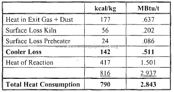
Ifwe look at the possibilities of bringing down the heat consumption, then about 25 kcal/kg
(0.09 MBTU/ST) can be saved in the exit gas by adding a 5th cyclone stage to the preheater,
but in some plants the full amount ofheat in the exit gas is used for drying the coal and raw
materials, so this heat is not wasted.
The surface loss from the kiln shell can be brought down by using a type of insulating bricks
in part of the kiln, but these bricks have generally a poor lifetime.
A better insulation in the preheater will partly result in a higher exit gas temperature instead
of saved heat input to the system.
Regarding the cooler, it is so that if we could establish a perfect counterflow in the heat
exchange between clinker and air, then nearly all the heat in the clinker could be transferred
to the combustion air. Therefore, the largest potential for bringing down the heat
consumption rests with the cooler.
III. COOLER TYPES
In the following the four (4) types of coolers, considered by the industry for modern cement
kilns, are discussed. These are: planetary coolers, rotary coolers, grate coolers (both
conventional and air-beam types), and cross-bar coolers.
A. Planetary Coolers
The planetary cooler served the cement industry for many years and was originally
designed for wet process kilns with a high amount of secondary air available for the
cooler.
In modern dry process kilns with a low heat consumption, the amount of secondary
air available for cooling (when this is done with secondary air only) is only about I
kg air per kg clinker (1 lb. air per lb. clinker) or even less. This requires a very
efficient heat transfer between air and clinker obtained by cascading the clinker
through the air flow. It also requires that the internal parts in the hot end can stand
high temperatures, which is obtained with wear resisting ceramic materials.
In a planetary cooler, such as the Unax, the principle of having a number of cooler
tubes rotating with the kiln and connected directly to the kiln is used.
A breakthrough for the new planetary cooling principles came when a kiln support
below the cooler was introduced. This permitted heavy cooler tubes with the
necessary internal fittings to be supported without excessive stresses in the kiln shel1
and opened the way for designing Unax coolers for kilns with a high capacity. The
one shown in FIGURE 3 is producing 4000 tid clinker (4,400 STPD), and the cooler
consists of 10 tubes, each 2.4 x 29 m (7’IO”x 94’9″). It is only for kilns having
capacity less than 1000 tid (1100 STPD) for which it is economical to leave out the
support below.
Each cooler tube is attached to the kiln with a fixed and a movable support, welded
to heavy kiln sections as shown in FIGURE 4.
The inlet to the cooler has a special design which prevents clinker from fal1ingback
into the kiln when a tube is in top position.
The cooling is based upon cascading the clinker through the air flow. This is not as
simple as it seems, as fine clinker falling down from the lifters through the air is
carried the wrong way by the air, and an excessive number of lifters has proved to
lead to overfilling the coolers, back spilling into the kiln and high exit clinker
temperatures.
The shape and number of the lifters in the various temperature zones have to be
carefully determined by means of a mathematical model, the input being an
anticipated grading of the clinker as shown in FIGURE 5.
At the cooler outlet the fine clinker falls through a grizzly to the clinker transport,
while coarse clinker and lumps are discharged at the side to a hammer mill clinker
crusher as shown in FIGURE 6.
In principle, coarse clinker requires more cascading and fine clinker less in the hot
end of the cooler in order to avoid excessive circulation between cooler and kiln,
which conveys more heat to the coolers. The inlet part with a special shape is lined
with castables. In recent years special, dense castables have been developed for such
a purpose, fulfilling all requirements regarding abrasion resistance, shock resistance,
chemical resistance against alkali attack etc., and the practical experience with these
modem castables has been very good.
In the cylindrical part ofthe coolers there is first a section ofcorrugated brick lining,
followed by cast heat resistant steel lifters of special design, either lined with steel
plates, as shown, or for the hot part with a ceramic lining, either bricks or castables.
In the cold end of the coolers, mild steel lifters with a high lifting capacity,
increasing towards the outlet, are used, and no lining is used here.
The outlet of the kiln to the coolers was previously made with steel casings, which
caused problems when exposed to high temperatures. The problems have been
solved by using a ceramic outlet made of the high quality, dense castables now
available.
The cooling effect depends, of course, on the size of the cooler. It can be expressed
as the clinker production in relation to surface and volume for the cooler tube by the
following formula:
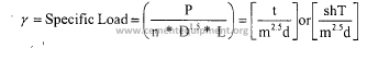
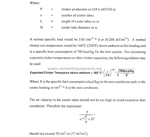
The temperature ofthe clinker from a Unax cooler ofan economical dry process kiln
will usually average 160°C (320°F) above ambient temperature. It can vary with the
clinker grading, and, ofcourse,it increases by forced output. The temperature can be
reduced, if required, by addition of water to the coolers ncar the outlet. The
equipment required is very simple: Just a gutter around the coolers, from which the
water runs into the individual cooler tubes. The amount ofwater is controlled by the
clinker temperature, and it has been established that I% water on clinker basis
reduces the clinker temperature by about 15-20°C (68°F), which is close to the
theoretical maximum. The effect on the heat consumption is therefore small, as long
as the amount of water is kept below 3% of the clinker weight.
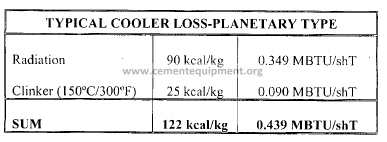
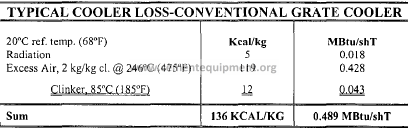
The heat losses from a planetary cooler consist of: (I) radiation loss and (2) sensible
heat in the clinker leaving the cooler. A normal cooler loss would be: (20°C ref.
temp./68°F).
This compares favorably with a conventional grate cooler especially when the
lower power consumption is also taken into consideration.
Depending on the cost relation between fuel and power, I kWh/t will often
correspond to the cost of 7 kcal/kg clinker (0.025 MBTU/shT).
It would, of course, be possible to insulate the cooler much better, but that would
lead to an excessive clinker temperature – a certain amount of heat has to be wasted
through radiation. The length of the different types of lining has to be chosen so that
the cooler shell temperature does not become excessive at any point
Another favorable feature is the low power consumption, only about 1.0-1.5 kWhJt
(0.9-1.5 kWhJshT) clinker added to the kiln drive and exhaust fan.
The Planetary cooler is unique in its simplicity, no excess air to handle, no motors or
fans, no instruments. In operation there is nothing to control, it is self-adjusting. One
disadvantage is that the clinker temperature is higher than for grate coolers. The
primary disadvantage is that the planetary cooler does not permit take-out for hot
tertiary air as required for modem calciner kilns. The higher noise level can also be a
problem in some areas.
B. Rotary Cooler
As mentioned above, the main drawback of the planetary cooler is that it was not
suited for modem precalciner kilns with external tertiary duct. This had (prior to the
dominance of grate coolers) given the separate rotary cooler a come-back.
The rotary cooler is also operated without excess air, but it permits take out of
tertiary air for a precalciner through a specially designed “rabbit-ear” kiln hood.
The cooler shown in FIGURE 7 is designed for a 2000 tid (2200 shT/D) kiln with
precalciner and has the dimensions 4.75 x 55 m (15’6″ x 180′), which means that it is
bigger than the kiln.
Just as for the planetary cooler, the cooling is based upon cascading the clinker but
with specially designed lifters, which prevent clinker from hammering on the lining
when dropping into the large diameter cooler. The mild steel section is divided into
six compartments so that efficient cascading is permitted..
The rotary cooler necessitates two efficient seals. The cooler has a 4.5% inclination
and a maximum rotating speed of 4.0 RPM. The power consumption for the cooler
drive is 3.5 kWh/t (3.2 kWh/shT).
Because the specific surface is lower than for a planetary cooler, the surface heat
losses are also lower, and that gives a favorable thermal efficiency, but it also results
in a higher clinker temperature, 200-250°C (390-480°F). Again, however, this can be
reduced somewhat by spraying water into the outlet.
The investments for a rotary cooler are higher than for a planetary cooler, but may in
some cases be lower than for a grate cooler when efficient cleaning of excess air is
required.
C. First Generation Grate Coolers
The grate cooler, however, is overwhelmingly accepted as the preferred method of
clinker cooling for today’s modern cement plants.
As shown in FIGURE 8, for the traditional grate cooler, the clinker drops from the
kiln onto reciprocating, air-quenching grates with compartmentized high-pressure
cooling fans.
Below the grates, the cooler is divided into a number of compartments, each
provided with fans having adjustable inlet vanes for automatic air flow control and
minimum power consumption. Clinker spillage through the grates is collected in
hoppers and removed through air-tight flap valves to the clinker conveyor.
FIGURE 9 presents the advantages of the grate cooler over other types of coolers.
As shown, the reasons for grate cooler’s preference are because the grate cooler is
capable of handling large outputs (10,000 MTPD or more) and because it is capable
of cooling clinker to very low temperatures (65°C above ambient or less). The grate
cooler as shown in FIGURE 10 also permits recuperation of hot tertiary air for
today’s precalciner kiln systems.
D. Second Generation Grate Coolers
The second generation (air-beam type) grate cooler has a standard cooler heat loss of
90 to 110 kcal/kg, which is a significant improvement over other cooler types such as
the rotary and planetary coolers. This, in itself, is remarkable since these other
cooler types operate without excess air; excess air being far and away the most
significant area of heat loss from the grate cooler.
Nevertheless, 90 to 110 kcal/kg (air-beam grate cooler heat loss) is still a substantial
portion ofthe overall loss of the kiln system. Therefore, the clinker cooler offers the
largest potential for further decreasing the heat consumption of modern
pyroprocessing systems as shown in FIGURE J]. Undoubtedly, further
developments will be made in the area of clinker cooling. One point is obvious: the
second generation (air-beam type) grate cooler represents a compromise between
reliability and efficiency. For this reason, third generation designs such as
F.L.Smidth’s Cross-Bar Cooler or Polysius’s Poly-Track Cooler or Claudius Peters
Eta Cooler or KHD’s Pyrotloor Cooler have emerged in recent years.
During the period of time since Fuller Company/F.L.Smidth first developed the airquenching
grate cooler during the late 1930s, the grate cooler emerged as the logical
choice for any new clinker cooler installation. Second generation grate cooler
designs employ a number offundamental design features that evolved over 60 years.
By the early 1990’s, all of the major cement equipment suppliers were offering
cooler designs that incorporated the latest developments in grate plate and air
distribution technologies. These “air-beam” technologies were integrated with the
fundamental design attributes which made the Grate Cooler an industry standard for
many decades.
The following section will highlight the mechanical design features present in all
second generation (air-beam) grate coolers and describe the maintenance and process
benefits of each.
1. Fundamental Design Features of Second Generation (Air-Beam) Grate
Coolers
Over the first 60 years since the introduction ofthe grate cooler, a number of
developments helped to make the grate cooler a reliable and efficient piece of
machinery; namely,
(a) Bridging (Dead) Grates and Evolved Grate-Line Configurations
(b) Grate-Line Suspension Systems (e.g. Internal Wheels)
(c) External Spillage Conveyors & Spillage Valves
(d) Reduced Fall Through Grates
(e) Hydraulic Grate Drives
(f) Clinker Crushers
(g) Three-Component Control System
(h) Air Beam Technology
(i) Elevated Resistance Grate Plates
(j) Stationary Inlet Section
Until the late 1990’s the design features listed above had been the universally
accepted staples of the modern grate cooler. Though variations in design
existed, all major equipment suppliers generally were offering the above
components. Moreover, the variations offered usually had very similar
results in actual practice. A description of maintenance and process benefits
of each component follows.
(a) Bridging (Dead) Grates and Evolved Grate-Line Configurations
. Bridging plates (dead grates) are the conversion of a moving plate to a fixed
plate by bridging from fixed row to fixed row over a moveable row. Fuller
Company/F.L.Smidth first installed bridging plates (dead grates) during the
mid-1960s in order to rectify problems associated with hot fines coming into
contact with side castings. Bridging plates (dead grates) as shown in
FIGURE 12A were installed adjacent to the side castings, then covered with
castable refractory to protect the cooler’s structural frame from the hot clinker
fines. Bridging plates (dead grates) were found to improve cooler
performance and increase capacity. Observation showed reduction in cooler
width gave a deeper bed depth and greater uniformity across the width ofthe
cooler.
With a deeper and more uniform clinker bed, it was found that the material
cooled quicker, the air to the kiln was warmer, and the operation of the kilncooler
was more stable. At the time of their development, dead grates
allowed for an increase in the cooler’s specific loading from 38 to 42
MTPD/m2
. Today dead grates also are used on modem air-beam coolers,
which have a loading of 50 MTPD/m2 or more. For these coolers, dead
grates and tapered refractory are installed on the static inlet rows as a means
to distribute clinker evenly across the cooler’s width.
1) Maintenance Benefit – Bridging plates (dead grates) act as a barrier
to prevent damage to the structural frame.
2) Process Benefit – The bridging plates allow deep bed operation,
improving cooling efficiency.
Over the years, many different grate line configurations have been employed.
The earliest grate designs were known as inclined coolers and were sloped at
10 degrees using horizontal grate plates. In order to re-gain control over the
clinker transport efficiency, grate lines of 5 degrees, 3 degrees, and
eventually 0 degrees (horizontal) were employed. The reciprocating action
•
of the grates takes place on a 10 degree inclination resulting in an overall
horizontal grate line as determined by the height ofthe grate’s pusher face as
shown in FIGURE i2B and FIGURE i2C.
For modern air-beam coolers, the transport capacity ofthe cooler is generally
increased due to a more complete aeration ofthe grate line. It is important to
control the clinker transport to avoid the possibility for “running” clinker, but
it is also important to minimize grate speeds so as to minimize wear. For this
purpose, a four (4) degree inclination of the grate line employing a
configuration of “one movable row followed by two stationary rows” has
been found by some suppliers as a proper compromise between grate wear
and transport efficiency.
(b) Alternative Grate-Line Suspension Systems
Since early cooler designs employed external wheels for carrying the
movable frame, a common maintenance problem was found in the area ofthe
sliding seals where wheel shafts penetrated the cooler housing.· Over the
years, it was found that the most simple and elegant solution to this problem
was the use of internal wheels as shown in FIGURE 13A and FiGURE 13B.
This eliminated potential loss ofcooling air and prevented clinker dust from
escaping through this area. Internal wheel design has developed to a point
where such components are essentially maintenance free. The preferred
design is a wide, flat wheel constructed of cast steel combined with antifriction
bearings. This design is essentially wear-free and so robust that a
sunken movable frame or a worn underside grate plate is unheard of. Center
guide rollers are used at standard locations along the movable frame to
ensure proper tracking. Finally, an automatic lubrication system, protected
by a large pipe diameter, keeps the bearings purged of contaminants.
I) Maintenance Benefit – Rugged, wide, flat wheels ensure minimal
wear and sturdy support of the movable frame.
2) Process Benefit – This arrangement eliminates the wheel seals as a
potential source of lost cooling air.
An interesting alternative to use of internals wheels to support the moveable
frame was patented by E.N.C.I. during the early 1970s. This concept known
as the “Pendulum Suspension” was subsequently adopted by lKN as shown
in FIGURE 13C and Claudius Peters as shown in FIGURE 13D during the
1990s. The idea was to suspend the moveable frame on long spring steel
straps (or a series of smaller straps) so that they are self-centering. This had
the advantage of being able to eliminate moving parts such as rollers and
bearings. The spring-steel strips were dimensioned so that, in the vertical
direction, the pendulum lift was 0.5 mm. This enabled the moveable gaps to
be set to I mm. The prerequisites are that the spring-steel strips do not
lengthen, the pendulums are correctly aligned, and that no settlement of the
foundation occurs.
1) Maintenance Benefit – Swing-type support systems eliminate rollers,
bearings, and lubrication points.
2) Process Benefit – Swing-type support systems better retain the widths
of unwantcd moveable gaps.
In general, these types of sophisticated “,[:WP managcment” systems had great
benefit for air-beam coolers in which the cooler’s performance is largely
determined by the size of the gaps between stationary and moveable grate
line components. This is because the cooling air will always take the path of
least resistance.
Of course, it is more beneficial to eliminate the gaps altogether by making
the entire grate line stationary. This iii precisely the reason for the
subsequent popularity of third generation coolers introduced during the late
1990’s. Such “cross-bar type” of coolers make sophisticated “gap
management” techniques obsolete. Moreover, the possibility for a
completely stationary grate line makes obsolete the following components:
(a) Dead grates, (b) Gap managemcnt systems, and (c) Spillage conveyors.
This is because clinker fall-through is completely eliminated.
(c) External Spillage Conveyor & Spillage Valves
Early on in the development of first generation grate coolers, it was found
that proper distribution ofcooling air into the respective undergratc chambers
was a predominant factor in determining the thennal efficiency ofthe cooler.
For this reason, Fuller CompanylF.L.Smidth led the industry in its
recommendations for small, controllable undergrate chambers. However, it
was recognized that proper distribution of this cooling air would still be
ineffective if the air were allowed to escape with the removal of undergrate
clinker spillage. Thus, modern coolers are equipped with an airtight floor and
pneumatically operated, double tipping valves for removal of spillage
without the loss of cooling air as seen in FIGURE 14. Coolers equipped
with an internal, open drag chain have sleeve seals between compartments,
but it was Fuller’s experience that these seals were not effective at the higher
undergrate static pressures demanded by the industry for improved efficiency
and deeper clinker bed depths. For this reason, the use of external spillage
conveyors and double tipping valves became a staple of modem cooler
design.
I) Maintenance Benefit – This method provides low maintenance,
pneumatically operated tipping valves.
2) Process Benefit – High pressure, deep bed operation results from
eliminating the spillage/product conveyor as a potential source oflost
cooling air.
(d) Reduced Fall Through Grates
Reduced fall through grate plates were first employed by Fuller
Company/F.L.Smidth in 1990 as an alternative to the conventional grate plate
with holes. The grates were designed to reduce spillage into the undergrate
area by means oflabyrinth-type slots as seen in FIGURE 15. In this regard,
their design is similar to modem air beam grate plates, which feature
labyrinth-type slots to prevent the possibility of clinker falling into the air
beam. These slots promote the uniform distribution of cooling air into the
clinker bed. In fact, many operators report that higher levels of aeration can
be accommodated without fluidization ofthe clinker layer as compared with
conventional grate plates with holes. Reduced fall through grates are
designed to be mounted on conventional grate plate supports with open
bottoms. Thus, the air enters RFT-type grate plates conventionally, that is,
by means of a pressurized undergrate chamber.
I) Maintenance Benefit – Less clinker fall-through minimizes damage to
undergrate components and spillage conveying system.
2) Process Benefit – Less spillage allows more clinker to remain
available for cooling/recuperation.
(e) Hydraulic Grate Drives
Since the mid-1980s, equipment suppliers have provided hydraulic grate
drives for grate coolers. Suppliers such as F.L.Smidth have since installed
them on nearly all new coolers. The development of the hydraulic drive
system advanced over time to offer more flexibility, reliability and greater
ease of maintenance than mechanical types. Force and motion are imparted
to each grate section by hydraulic cylinder(s) attached to the cross-head shaft.
Sized to overcome expected loads at normal – and maximum – system
pressures, the system is designed to provide a full stroke length, regardless of
speed as seen in FIGURE 16.
I) Maintenance Benefit – Require less maintenance than mechanical
types.
2) Process Benefit – Offer greater ease to move cooler out from under a
load condition, thereby offering the potential for increased
availability.
From a technical standpoint, hydraulic drives offer the following advantages
over electromechanical designs:
I) Possible to vary the speed as conditions require.
2) Possible to vary the operating pressure as conditions require.
3) Hydraulics are much better in jam conditions because they provide
less shock on the mechanical components.
4) Opportunity to run at significantly different speeds and pressures,
because of the flexibility one gets with using hydraulics.
5) It is much less likely to stall or overload the electric motor with
hydraulics, because hydraulics have a relief valve for overload
protection.
(f) Clinker Crushers
Clinker Crushers are employed to reduce clinker lumps to typically less than
25 mm. This is done either by means of a conventional clinker breaker as
seen in FIGURE 17 at the discharge of the cooler or by means of a modern
roll crusher as seen in FIGURE 18 at either a mid-cooler or end-cooler
position.
Though roller breakers are sometimes used to replace conventional clinker
breakers, they were primarily designed to create more uniform size reduction
for better cooling obtained by mounting between the drives of the cooler.
The roll breaker provides distinct advantages over the conventional hammer
mill type: It runs slower, creates less dust, and receives less wear.
I) Maintenance Benefit – Causes less wear than conventional hammer
breaker due to lower speeds.
2) Process Benefit – Improved cooling results from increased surface
area.
The rollers consist of transport and crushing rolls. The number of rolls is
determined by the capacity of the unit. The transport rolls tum at
approximately 2 rpm; crushing rolls at about 4 rpm. By comparison, the
operating speed of a conventional hammer mill is about 350 rpm. Normally
roll breakers are hydraulically driven and the rolls automatically reverse if
material jams in the rolls. A unique feature of F.L.Smidth’s HRB (heavyduty
roll breaker) is the ability to reposition the first crushing roll to
compensate for wear and thereby maintain clinker product size. This socalled
“exclusive cavity feature” also enables the efficient size reduction of
very large (e.g 1m diameter) clinker balls.
(g) Three-Component Control System
The grate cooler is based on cross-current cooling air. It therefore needs more
air for cooling than can be used in the precalciner kiln, and the excess air
must be removed and dedusted.
The amount of air needed depends very much on the type ofgrate cooler (airbeam
or conventional) but varies also according to the clinker grading and to
the clinker temperature required. It is costly to cool to low temperatures, but
often this is a requirement for cement grinding operations.
Efficient sealing between the compartments permits operation with relative
high and different pressures in the various compartments. With a normal
clinker bed of 750 mm (30″) the pressure drop at a constant air flow per m2
of grate area will decrease from about 750 mm WG (30″) in the hot end to
about 250 mm WG (10″) in the cold end. The fans are sized accordingly, so
that the maximum pressure decreases from 810 to 300 mm WG (32″ to 12″).
For trouble-free operation it is an advantage to use a larger air flow in the hot
end, up to 150 kg/rnin.zm” (400 SCFM/Ift\ and less in the cold part,
minimum 60 kg/min.zrn” (165 SCFM/ft2
) .
The width of the grate is typically reduced at thc inlet in order to spread the
clinker more evenly. Having a high air flow and a thick layer of clinker, it is
possible to get an imperfect, but acceptable, uniform clinker bed and a usable
air flow over the width of the grate. This is essential not only to avoid local
overheating of the grate in the fine side of the clinker but also to avoid
“snow-men”, as the clinker is kept moving throughout the whole grate until
the surface solidifies.
The speed ofthe grate can normally be varied between 4 and 25 strokes/min.
Normal operation is typically 10-12 strokes/min. Efficient cooler operation
requires automatic control. A simple and reliable system involves three main
functions as described below and depicted on FIGURE 19A, FIGURE 19B
and FIGURE 19C.
I. Constant air flow to each under-grate compartment (using piezometer
or some other air-flow device).
2. Constant under-pressure in kiln hood (using pressure indicators
spaced around the circumference of the kiln).
3. Regulation of grate speed for constant bed thickness (using the
pressure under the first or second under-grate compartment as a
measure ofbed depth). Note: The second and third grate sections are
usually “slaved” in proportion to the first one.
If the clinker happens to become very coarse, the undergrate pressure may
not correspond to the bed depth, and in such cases the pressure control may
be overruled by the power consumption of the grate.
Such a simple system functions without problems, and in automated plants it
can be supplemented with automatic control of the clinker temperature or
constant air flow to the grate for a given capacity.
(h) Air Beam Technology
In a conventional grate cooler, air distribution and, therefore, cooling
efficiency, is largely determined by the mechanical condition ofthe cooler. A
significant improvement in grate cooler efficiency was gained in the late
1980s with IKN’s introduction ofair beams at the inlet to the cooler. During
the early 1990’s, all major equipment suppliers developed air-beam systems
and such systems largely replaced conventionally aerated grate coolers. In
essence, air beam systems prevented the possibility that cooling air could
bypass the clinker layer. In this way, air beam technology worked by
improving the air distribution below the grate by connecting individual rows
of the cooler directly to the air supply, rather than by blowing air into the
undergrate chamber in the conventional manner as seen in FIGURE 20. In
such systems, the grate plate supports were used to duct the cooling air
directly to the grate plates and into the clinker bed. Depending upon the
equipment supplier, the air beam was further subdivided across the width of
the cooler such that only a few individual grate plates received air from a
separate, controllable source. Preference was given to the extension of air
beams throughout the entire recuperation zone ofthe cooler. For this reason,
most equipment suppliers developed air beam systems for use on both the
stationary and movable rows of the cooler. However, in many markets,
simplicity (rather than efficiency) was the key and, therefore, Hybrid Designs
(which incorporate air beams only on the stationary rows) were developed as
shown in FIGURE 21.
1) Maintenance Benefit – Air beam technology improves cooling of
grate plates and supports.
2) Process Benefit – This method Improves cooling air distribution
below grate, minimizing the effect of the cooler’s mechanical
undergrate condition on thermal efficiency.
Favorable results were demonstrated in a number of coolers that were
converted from conventionally aerated grates to air-beam systems. Results
were shown to be dependent upon how many of the existing rows were
converted to air beam technology as depicted in FIGURE 22 (Table of
Results). Savings in fuel consumption resulted in a reduction of kiln and
preheater exit gas, both in terms of mass flow and temperature’. In most
instances, this reduction was used to increase clinker capacity.
(i) Elevated Resistance Grate Plates
A well known phenomena in the traditional grate cooler is the “red river”,
which is a narrow stream of the clinker, which continues far down in the
cooler at a temperature, which far exceeds that ofthe neighboring clinker. It
is often red hot (hence the name) long after the other clinker has turned dark,
and it has been seen, that such “red rivers” can reach the clinker crusher.
This is due to the difference in resistance to the air flow across a transverse
section of the cooler. The fine clinker offers a much lowerresistance to the
air flow, than does the coarse clinker and the air, of course, takes the easiest
path. The clinker segregates out of the kiln, with the fine clinker on the kiln
load side and the coarse clinker on the other. Furthermore the air is not
confined to the holes in the grate plates, but can also pass between the gaps
between the grate plates. Investigations have shown that as much of60% of
the cooling air may pass in the gaps between grate plates, thus decreasing the
quality ofthe air distribution. Since it is easier to blow air through the coarse
clinker layer, an excess ofair must be applied to the component asa whole to
ensure that enough air is applied at the fine side. FIGURE 23A, FIGURE
23B, FIGURE 23C, FIGURE 23D and FIGURE 23E show how this
phenomenon effects the air distribution in traditional coolers and how it can
be avoided in a modern grate cooler.
The distribution of air in the clinker bed is best described by watching the
pressure drop through a cold layer ofclinker. This can be described by Ergun’s
equation as follows:
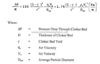
In FIGURE 24 the pressure drops of various clinker sizes are shown as a
function of the free air velocity. The dramatic influence of particle size on air
distribution is clearly seen.
Let us look at an example where the “fine” side mainly consists of2 mm clinker
and the “coarse” side of 5 nun clinker. Here the relationship between air
velocities will be 1/5, meaning that only approx. 17% ofthe cooling air is blown
up through the “fine” side and the rest in the “coarse” side. In cases where the
kiln is producing very dusty clinker, red river will usually be an almost
inevitable consequence.
Air beam systems ensured that virtually all of the cooling air was directed
into all areas of the clinker bed (where some air may have otherwise
bypassed the clinker layer altogether). However, the air distribution above
the grate line was largely influenced by differences in granulometry within
the clinker layer, itself. To ensure a more uniform air distribution above the
grate line, suppliers developed increased flow resistance grate plates for use
with their air beam systems. These grate plates must have anti-sifting
features so that clinker dust cannot fall through the plates and into the air
beams (even if the air supply is interrupted). The increased flow resistance
gives high-pressure losses shown in FIGURE 25.
The higher-pressure losses “normalize” the effects of unequal airflow
velocities through the clinker caused by different regions ofresistance within
the clinker bed. This results in an even-velocity profile in all areas of the
clinker bed and a low-mean velocity value. This lower-mean velocity
through the clinker layer tends to reduce the quantity of dust recirculation
between the kiln and cooler, thereby improving the cooler’s recuperation
efficiency as depicted in comparative Figure 23A, Figure 23B, Figure 23C,
Figure 23D and Figure 23E.
Over the years many different systems were developed, but common for all the
systems and the “secret” behind any type any of the second generation grate
coolers was the “built in” resistance in the grate plate which is approximately 25
mbar at an air quantity of approximately 110 kg air/mvrnin, By having this
initial resistance, the air supply will “even out” to the individual plates within
an aeration field.
I) Maintenance Benefit – Lower thermal loading of grate plates is
possible.
2) Process Benefit – Improved cooling air distribution above the grate
minimizes the effect of clinker granulometry on thermal efficiency.
Each of the second generation equipment suppliers had proprietary grate
plate designs. Typically, second generation grate plates had narrow air
stream apertures designed to create flat air jets and high-pressure losses as
shown in FIGURE 26. However, the physical differences between these
grate plates was less important than the fact that it was the grate’s air-flow
resistance that gave the desired heat exchange. As long as flow was uniform
over the entire grate surface, then the distribution of cooling air through the
clinker layer was also uniform, provided the bed is not too deep.
A satisfactory level of grate resistance is on the same order of magnitude as
the bed resistance and a satisfactory air distribution is one that allows high
aeration rates without fluidization of the clinker bed.
The basic philosophy behind all of the second generation grate systems was
to provide a more uniform distribution ofair through the clinker bed in a way
such that the heat transfer was maximized. It is a scientific fact that the
cooling air always seeks the path oflcast resistance. With this in mind, all of
the major equipment suppliers devised schemes to gain more control over the
air distribution. While Air Beam Technology works by improving the cooling
air distribution below the grate line, Elevated Resistance Grate piates work
by improving the air distribution above the grate.
OJ Stationary Inlet Section
By the end of the 1990’s, stationary inlet sections had become a universal
feature of all new grate coolers. Fixed inlet designs deliver a higher degree
of utilization and minimize overall maintenance costs. For this reason,
second generation cooler designs (and also third generation designs) employ
some type of stationary inlet section offering a rigid support against the
impact of chunks. This largely eliminates wear due to the absence of any
movable parts.
Equipment suppliers have all adopted the use of a stationary inlet, sloped
section of 3 to 8 rows of air beams inclined at about 15 degrees as shown in
FIGURE 27. Individual designs vary from one supplier to another, but these
design features are less important than the reasons for the derived benefits:
(I) maintenance savings result from the absence ofany moving parts and (2)
fuel savings result from the use of air beam technology.
1) Maintenance Benefit – Having no moving parts ensures extended
grate plate life for many years; rugged stationary designs protect
grate plates from falling clinker/coating.
2) Process Benefit – May provide lower efficiency than alternating
movable and stationary air beams for operational reasons; however,
little is gained in relation to maintenance savings gained through the
absence of any moving parts.
Preferred Inlet Systems allowed the operator to control the amount of air to
each side of the cooler and to each row of the static section. Preference was
given for a 5 to 9 row stationary inlet module. In the subsequent stationary
and movable grate section, a grate slope of 2-4 degrees was preferred to
minimize grate speed and grate wear. Again, preference was given to the
extension of air beams throughout the entire recuperation zone ofthe cooler.
2. Process Considerations
The above section has identified the mechanical design features present in
first and second generation grate coolers and has described the maintenance
and process benefits of each. In the sections that follow, the impact of these
mechanical components on process design will be considered.
Handling and dedusting of the excess air is the main disadvantage of the
grate cooler and is also decisive for a comparison between the investment
costs of different cooler types.
The excess air varies with regard to quantity, temperature and dust content,
and the system for its handling, of course, has to be designed for the worst
condition. F.L.Smidth typically uses design figures corresponding to 2.8 kg
. excess air/kg clinker (2.8 Ib/lb clinker) and 400°C (700°F) for conventional
coolers and about 1.9 kg/kg clinker for air-beam grate coolers.
The preferred method of handling the excess air is by means of an air-to-air
heat exchanger and bagfilter. Air cleaning with multi-cyclones is not
acceptable in a modern plant.
Another option is to use electrostatic precipitators for excess air. They have
proven reliable and efficient with low operating costs. To reduce the size of
the precipitator, a small quantity of atomized water can be injected through
nozzles in the cooler ceiling/exhaust gas duct during upset conditions.
However, a study of investment costs between precipitators and bag filters
demonstrates the cost effectiveness of bag filters over precipitators for
emission requirements of less than 50 mg/Nrrr’ (dry basis). This is because
the size ofthe precipitator increases exponentially with decreasing emissions
levels whereas the size of the fabric filter remains constant. For this reason,
bag filters combined with air-to-air heat exchangers are preferred in many
parts of the world, where demands for very low emission rates are required.
The decisive factors for the choice between these solutions are operating
costs and reliability, especially the ability to cope with upset conditions.
The advantage ofthe grate cooler is that it is independent ofthe kiln and very
flexible with regard to production. Also a low clinker temperature can be
obtained, 65°C (150°F).
An important consideration is the high power consumption of the grate
cooler, for conventional type cooler 5-7 kWhit (4.5-6.3 kWhlshT), exclusive
of power for dedusting. Depending on the cost relation between fuel and
power, I kWh/t will often correspond to the cost of? kcal/kg clinker (0.025
MBTU/shT).
3. Efficiency, Recuperation and Cooler Heat Losses
When you wish to specify a new cooler or evaluate how well your existing
cooler is performing with respect to heat recuperation and cooling of the
clinker, it is convenient to be able to do that by means ofsome characteristic
key figures. Often, terms like cooler efficiency, heat recuperation or cooler
loss are used.
It is necessary to define exactly what we understand by those terms and how
we calculate them.
The grate cooler heat losses consist of(1) radiation loss, (2) heat contained in
the hot excess air and (3) sensible heat in the clinker leaving the cooler as
shown in FIGURE 28.
A typical heat loss for a conventional grate cooler would be:
In cases where low-temperature heat can be utilized for drying of raw
materials or coal, up to 50 kcal/kg clinker (0.180 MBTU/shT) of the waste
heat can be recuperated and then, of course, the thermal efficiency becomes
very favorable.
The heat recuperation is also at times called cooler efficiency. It is necessary
to know the temperature of the clinker coming from the kiln to calculate the
% heat recuperation; this temperature is nearly impossible to measure.
Arayo-tube gives incorrect values, because the clinker at the kiln outlet is
often covered with a layer of dust coming from the cooler, and also the
temperature at the surface can be different from that in the center of the
clinker particles. It is also difficult to take out a representative sample of
clinker into a bucket and to measure the temperature outside the kiln.
What is important for the heat consumption 111 the kiln is the heat
recuperation from the moment the clinker leaves the burning zone. The
burning zone temperature is also difficult to measure, but often I450°C is
taken as a standard value.
For the same cooler working with the same type of clinker, the heat
recuperation will depend on the amount of combustion air that goes from the
cooler to the kiln. This amount again depends on the heat consumption,
excess air for the combustion, the amount of primary air and the amount of
false air through the kiln seals.
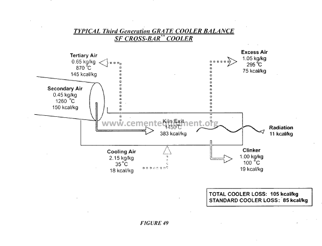
FIGURE 29 shows the cooler loss and heat recuperation in relation to the
amount of combustion air. The different lines represent coolers with
different recuperation abilities. As the grate cooler is not a cooler with a
perfect counter-flow, there is an absolute maximum for the heat recuperation
ability. The lines K = 1.00 represent such an ideal cooler with maximum
recuperation ability.
The curve K = 0.23 corresponds to a traditional cooler working well.
The following comments can be made on the amount of combustion air:
A dry process kiln using 750 kcal/kg clinker will only need half as much
combustion air as a wet process kiln using J500 kcal/kg clinker. It is
therefore obvious that the cooler loss will be much less for the wet process
kiln than for the dry process kiln, even when the amount and temperature of
the clinker from the kiln, and of the cooling air blown into the cooler, is
exactly the same in both cases.
The only difference is: (1) the amount and, (2) temperature of the excess air
will be very much different; clinker temperature and surface loss of the
cooler will be the same in the two cases.
Figures for cooler losses are therefore without meaning if the amount of
combustion air from the cooler to the kiln system is not known. The same, of
course, applies to cooler efficiency or recuperation percent which is basically
100 minus the cooler loss expressed as percent of the heat in the clinker
leaving the kiln.
Although it is possible to measure the amount of tertiary air on precalciner
kilns by a Pitot tube or similar, there is no way to measure the amount of
secondary air from cooler to kiln tube. It is therefore better to determine the
amount of recuperated air by calculation, Lambda = 1.00.
Usually the figure works out at about 1.41 – 1.42 kg air per 1000 kcal lower
(net) heat value fired when the fuel is bituminous coal or fuel oil; for fuels
with a high content of water the figure will typically be higher.
The combustion air actually used will (in addition to the stoichiometric air)
also include the air excess, which can be calculated from the 02 – and CO2content
in the gas after the combustion process, .The formula is:
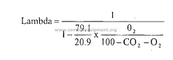
Lambda = 1.20 for instance means that there was 20% air excess where the
gas analysis was made.
From the total combustion air Lcom = Lambda x Lmin it is necessary to
subtract the various sources of false air, including primary air, which do not
come from the clinker cooler.
The most complicated case is when there arc two combustion processes in
series, such as ILC precalciner kilns.
Estimation ofthe secondary air requires a measurement ofthe 02 – and CO2percent
in the kiln tube exit. From this the lambda value can be calculated
and hence Lcom.
Not all of this air has come from the cooler. The primary air, including
transport air for coal meal (if any), must be measured and subtracted.
Further, false air entering at the kiln outlet seal between kiln tube and kiln
hood and through gaps in the kiln hood, must be subtracted.
If the probe sampling the gas after the kiln tube is not located inside the kiln
tube, but rather in the riser duct, false air entering through the kiln back end
seal must also be subtracted.
The tertiary air can be determined in a similar way. Lmin for the total
amount offuel burned in kiln and calciner is calculated. O2 and CO2 after the
calciner are measured, and the lambda is calculated. The total amount of
combustion air is calculated.
From this must now be subtracted secondary air from cooler to kiln, primary
air to kiln burner, false air at kiln hood/outlet seal, false air through back end
seal, primary air/transport air calciner, false air in calciner and false air in
tertiary air dust trap. IfO2 and CO2 analysis are not made immediately after
the calciner but after the top cyclone, false air in the cyclone preheater
including air from pneumatic kiln feed transport (if any) must also be
deducted.
Cooler losses are usually measured and calculated according to rules laid
down by the German Cement Makers Association VDZ, which use ambient
temperature as the reference. When calculating the recuperation efficiency,
VDZ assumes a clinker temperature of 1450 °C and nil dust circulation
between kiln and cooler. The latter can have a huge influence on the actual
cooler loss. VDZ further does not take into consideration that practically all
mechanical energy put into the cooling fans has been converted into heat
when the air leaves the surface of the clinker bed with zero pressure and
velocity. The latter can be eliminated if the temperature of the cooling air is
measured on the pressure side of the fans.
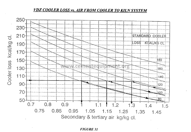
FIGURE 30A and FIGURE 30B give the definitions for Cooler Loss
including Total Cooler Loss (reference temperature DoC), VDZ Cooler Loss
(reference temperature = cooling air temperature), and Standard Cooler Loss
(normalized combustion air requirement). F.L.Smidth has introduced the
concept standard cooler loss, which means the VDZ cooler loss at a
total recuperated amount of cooling air of 1.155 kg/kg clinker. Similarly, the
standard efficiency must refer also to 1.155 kg/kg clinker ofrecuperated air.
FIGURE 31 shows how the cooler loss and process heat recuperation vary as
a function of the amount of recuperated air;
The more recuperated air, the
lower the cooler loss and the higher the recuperation efficiency.
4. Impact of Second Generation Grate Coolers (Air-Beam &
Elevated Resistance Grate Plate Designs)
A significant development in the efficiency of grate coolers was made in the
early 1990’s with the introduction of (I) Air-Beam technology and (2)
Elevated Resistance Grate Plates.
The amount ofair for air-beam coolers generally lies between 2.3 and 2.6 kg
air/kg clinker (2.3-2.6 lb air/lb) but in order to cope with forced conditions
and fluctuations, we normally install a fan capacity corresponding to approx.
2.8 kg air/kg clinker (2.8 Ib air/lb). In comparison, the conventional type
grate coolers were designed for 3.5 to 3.8 kg air/kg clinker (3.5 to 3.8 Ib
air/lb ).
The specific load of new type grate coolers expressed in tid per m2 is
normally 45-50 MTPD/m2 compared to 38-42 MTPD/m2 for conventional
grate coolers. This higher grate load is mainly possibly due to a much better
heat recuperation in the air-beam type grate coolers which allow for a lower
retention time and partly the result of the tendency to work with a thicker
clinker bed.
Air-beam coolers and modem grate plate designs were developed in response
to traditional deficiencies of the conventional grate cooler (such as the air
taking the path of least r.esistance) whose correction would contribute to
better grate lifetime and better heat recuperation.
It is clear that the area on which attention should be focused is in the first
section ofthe cooler (heat recuperation zone). Ifmore heat can be recovered
from the clinker and utilized in the process, we can save energy and obtain a
more stable kiln and cooler operation.
Many different second generation grate systems were developed, but
common among all was a “built-in” resistance across the grate plate which is
approximately 250 mmWG (lOinWG) at an air quantity of approximately
110 kg air/m2/min (300 SCFM/ft\
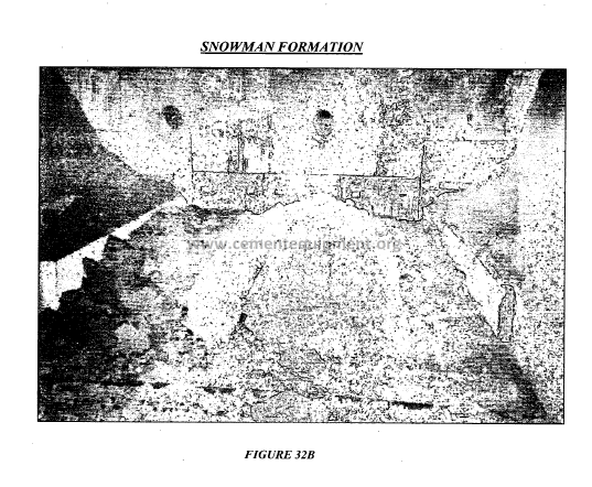
To have full control over the flow/speed of the clinker layer, to avoid “red
rivers” as shown in FIGURE 32A, and to guard against “snowmen”
formations as depicted inFIGURE 32B, a preferred grate arrangement uses a
horizontal grate layout and a moveable first row. However due to
maintenance reasons and the general lifetime of the impact zone, the use of
five to eight stationary rows at a slope of approximately 15°became widely
accepted. For this reason, most equipment suppliers such as F.L.Smidth
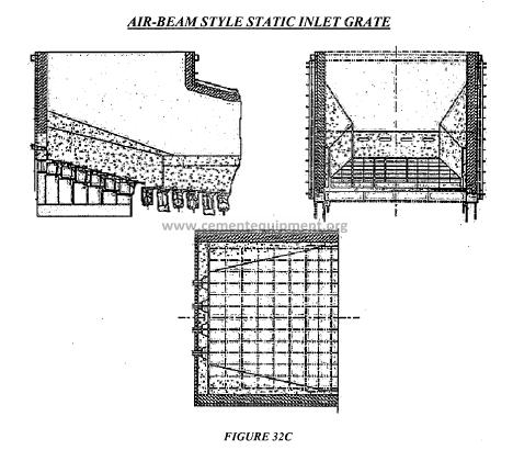
today use an inclined impact section. To avoid material build up and
“snowman” formation it is necessary to install air blasters for the stationary
inlet section, depending on the clinker materials tendency to form
“snowmen” and the cooler size as shown in FIGURE 32C.
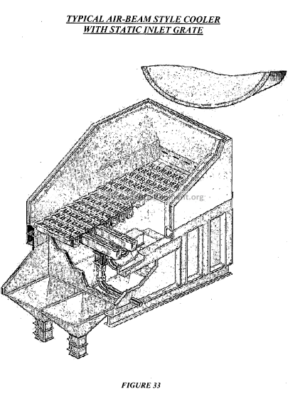
After the Stationary Inlet Section, second generation cooler designs typically
employed a series of air-beam grates that covered the rest ofthe recuperation
zone as shown in FIGURE 33. As shown, preference was often given to the
use of grate sections inclined at 2° – 4° where every second and third grate
row was stationary. Operational complexity is clearly minimized by
maximizing the number of stationary rows compared to moveable rows.
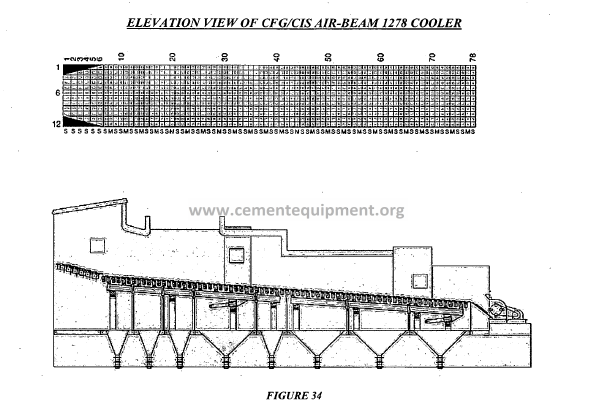
After the air-beam section, Reduced Fall Through grates typically covered
the rest of the drive sections as shown in FIGURE 34.
If required, the air beam system can cover the entire cooler grate area, but
due to increased operational complexity and cost, such an arrangement is
uncommon. When air-beams are extended throughout the recuperation zone,
the result is a more efficient grate cooler where the heat recuperation is
greatly improved compared to coolers of conventional design.
The overall result of an air-beam cooler compared to a conventional cooler
IS:
30 – 40 kcal/kg clinker reduction in standard cooler loss.
Reduced size of Cooler, approx. 30%
30 – 40% reduction in size of Cooler ventilation system.
Improved Kiln and Cooler operation.
Possibly lower maintenance cost.
Reduced tendency to “red river” formation.
345
Not only new coolers can be supplied with the air-beam systems. An
existing, conventionally aerated grate cooler can be modified to include airbeam
features. With the air-beam systems, the grate load may be increased
(and together with an improved heat recuperation) the clinker production can
be increased.
For a retrofit, normally only the first cooler grate is modified. The remainder
of the grate(s) and cooling systems are left untouched. By retrofitting the
complete first grate, maximum benefits will be delivered since this grate (in
most cases) will cover the complete heat recuperation zone. However, the
system can also be offered for less than the complete first grate, i.e. installing
a static inlet section only.
In addition to the operating advantages, there are compelling economic
considerations like heat savings of 30-85 kcallkg clinker, a yearly capacity
increase typically in the neighborhood of5% and a payback time ofless than
1 year.
Conversion of an existing cooler to a modem air-beam type offers some
evident operational benefits, including:
heat savings of 30 – 85 kcallkg clinker
reduced dust circulation
reduced air consumption
During the Work Session on Clinker Coolers, you will have the opportunity
to make an estimate of the heat savings resulting from a retrofit to the
cooler’s first grate. You will find that the savings is proportional to the
amount of “air-beam” air. In other words, the savings is proportional to the
number of installed air-beam grates rows, but also to the mechanical
condition of the cooler. As will be shown, when carrying out a retrofit, it is
preferable to change the complete recuperation zone. With careful planning
retrofits can be undertaken very efficiently (typically, the erection can be
done in less than 3 weeks during a planned kiln stop).
5. Second Generation Grate Cooler Summary & Commentary
From the late 1980’s until the late 1990’s, the cement industry’s cooler
market had been dominated by air-beam technology and resistance grate
plates. All major equipment suppliers offered some type of air-beam
technology and high-pressure resistance grate plate designs. Unquestionably,
these technologies made improvements over the conventional grate cooler, in
particular, improvements were made to the air distribution below the grate,
through the grate, and above the grate. As a result, the heat transfer between
the air and clinker improved and substantial reductions in specific cooling air
requirements were realized.
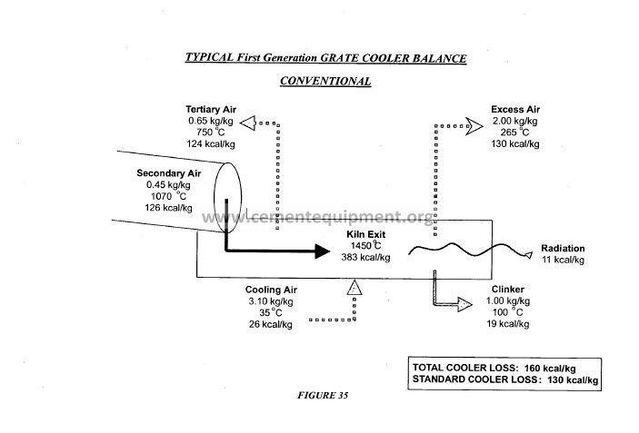
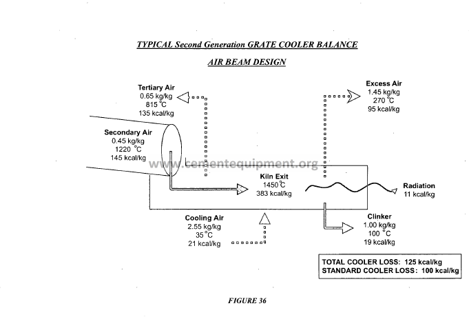
Taken as a whole, continually improved design features made it possible to
substantially improve the thermal efficiency ofthe grate cooler from 1990 to
2000. FIGURE 35 and FIGURE 36 present comparative heat balances of
typical grate cooler performance resulting from design improvements during
the 1990’s. As shown, it was made possible to reduce the cooler’s heat losses
from 160-130 kcal/kg to 125-100 kcal/kg or even less. These heat loss
savings were the result of a reduction in the specific cooling air requirement
from 3.1 kg air/kg clinker to 2.5 kg air/kg clinker during this time. This
reduction in cooling air input resulted in a ‘corresponding reduction in the
cooler’s excess air requirements from 2.0 kg air/kg clinker to 1.4 kg air/kg
clinker, thereby decreasing the capital costs of cooler vent systems.
However, the grate cooler of the mid 1990’s still represented a compromise
between efficiency and reliability. In many respects, potential process
benefits had taken a back seat to maintenance benefits, or more aptly,
availability. This was because mechanical simplicity is favored over process
complexity. That is, despite dramatic improvements, the air-beam grate
coolers of the mid 1990’s were still plagued by relatively high maintenance
costs and operational complexities associated with these equipment
innovations. Disadvantages included:
• The valves, pipes, dampers and connectors for the air-beams required
operator adjustment. Furthermore, these components precluded
access to the under-grate chamber.
• Since the cooling and conveying mechanisms were integrated,
air-beam coolers suffered from deteriorating cooling performance as
the grate plates (located in the moving sections) began to wear.
• The requirement to supplement “air-beam” air with “sealing” air (i.e.
air introduced in the conventional manner) was one of the primary
disadvantages of the high-pressure resistance grate plate designs.
• The continued possibility for clinker fall-through with any moveable
grate system and the resultant need for an under-grate spillage
conveying system constituted a further disadvantage.
For these reasons, in 1996, engineers at F.L.Smidth set out to develop a
cooler that was superior to the second generation grate coolers (i.e. the most
efficient of air-beam coolers). The goal was to develop a cooler having
maximum availability by focusing on a design which was simpler to operate
and simpler to maintain than either the conventional grate cooler or the
air-beam technologies. Many ideas were proposed and discussed. The
requirement was to separate the cooling mechanism from the conveying
mechanism so that there would be absolutely no deterioration of cooling
efficiency over time, inefficient sealing air would not be required, clinker
fall-through would be eliminated, and the needfor under-grate sealing and
transport systems could be avoided.
E. Third Generation Coolers
The clinker cooler is a critical component in the cement manufacturing process and
has been an area of great innovation over the years because it represents the greatest
potential for further improving the heat consumption oftoday’ s modem kiln systems.
In 1997, arguably the most revolutionary development witnessed by the cement
industry in the last fifteen years took place when the first 3’d generation clinker
coolers were put into operation. These 3rd generation coolers were characterized by
the following innovative features: stationary grate line, separation ofthe conveying
and cooling mechanisms, modular design, and active airflow control to every grate.
These breakthrough technologies have subsequently led to the current clinker cooler
innovations that are sweeping the industry. The 3’d generation designs provide high
reliability, low maintenance costs, and excellent process efficiency. In some cases,
the 3’d generation technologies have become more affordable because they can be
retrofitted into any cooler, resulting in significantly lower installation costs.
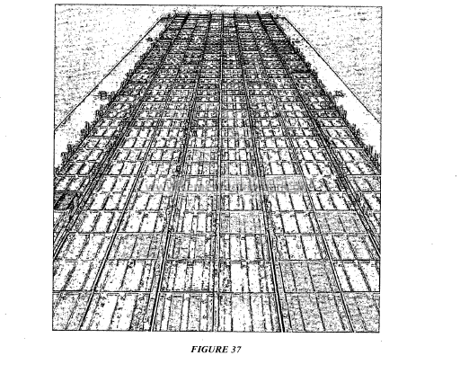
F.L.Smidth was the first supplier to implement a 3’d generation cooler technology (in
1997) which was characterized by the following innovations:
• Stationary Grate Line for the Entire Cooler (FIGURE 37)
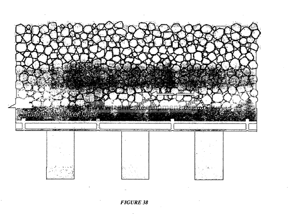
• Separation of Conveying and Cooling Functions (FIGURE 38)
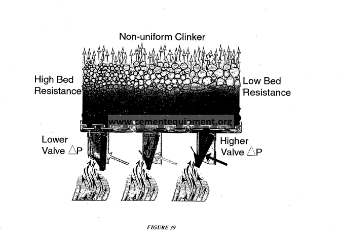
• Flow Regulation to Every Grate Plate (FIGURE 39)
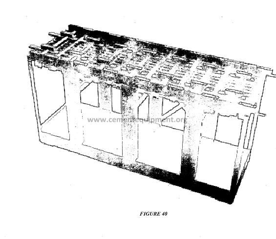
• Modular Design (FIGURE 40)
The key benefits of these technologies can be summarized as follows:
• Significantly Improved Reliability
• Reduced Maintenance Costs
• Predictable Maintenance
• Commonality of Spare Parts
• High and Constant Thermal Efficiency Over Time
• Quick and Easy Installations
• Workshop Quality
Due to the separation of cooling and conveying functions, the technology became a
win-win solution for both the plant process engineer and maintenance manager.
Modular design reduced installation times and the ‘split-drive’ configuration (e.g. by
modules or “tracks” or “lanes”) enabled both flexible operation and extremely high
availability. With the 3’d generation designs, down-time caused by the clinker cooler
generally became a thing ofthe past. With F.L.Smidth’s successful implementation
of these new technologies, competitors began to develop new designs over recent
years. These new designs largely draw upon the success of the original, innovative
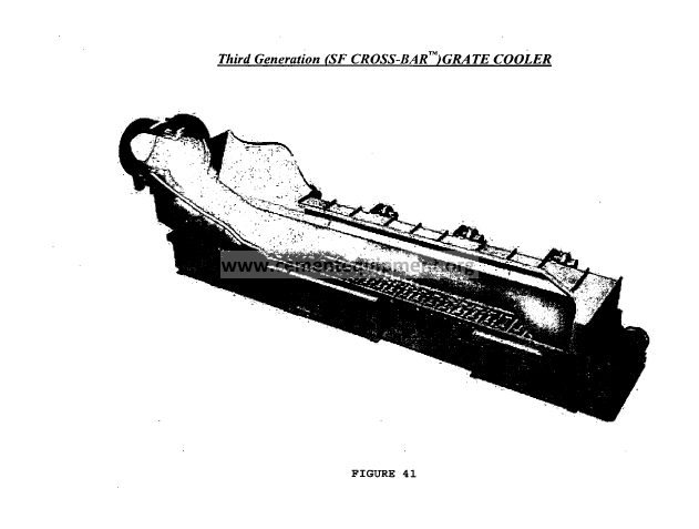
features first developed in 1997, generically known as the “cross-bar cooler”
FIGURE 41 as presented below.
1. Fundamental Design Features of Third Generation Grate Coolers
(a) Modular Design
The entire cooler is constructed in modular form. A typical module is four (4)
plates wide and fourteen (14) plates long (1.3 m wide and 4.2 m long) as
depicted in FIGURE 40.
A single module could be a whole cooler or several modules could be
assembled to form a larger cooler. The modules are set side-by-side and endto-
end.
The modules consist of an under-grate chamber with a grate-line at the top.
The air distribution plates are supported on a stationary tray system. The
grate line is completely stationary so there is no deterioration of cooling
efficiency over time.
The “modular design” is demonstrated in that each module can be preassembled
prior to installation, including its refractory. The modules are
simply set side-by-side and end-to-end. As a result, existing grate coolers can
be completely replaced with a new “cross-bar” cooler in as little as 3 to 4
weeks. Also, because all modules are duplicates ofone another, it is possible
to significantly shorten delivery times.
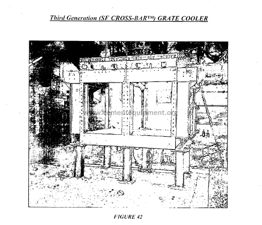
(b) FixedGrate-Linefor Air Distribution
Just as for a conventional grate cooler, the grate-line sits atop a under grate
compartment as shown in FIGURE 42. However, because the sealed grateline
is completely stationary, the grate plates can be locked together for
maximum process efficiency.
The sealing system of the grate-line is so effective that no devices are
provided for removal of spillage from the under-grate chamber. The bottom
of the under-grate chamber has a steel floor without any openings. No
spillage removal valves are provided and no spillage conveyor is installed
under any of the cross-bar coolers. This means less items for maintenance. It
also means lower head room requirements. For new kiln line installations, the
lower head room requirements may yield a savings of 2 – 4 meters in height
for the entire pre heater tower and kiln which significantly contributes to
lower civil costs. For existing installations, it enables the cross-bar cooler to
replace existing coolers with low headroom (i.e. coolers with internal drag
conveyors or disc gate spillage removal systems).
Unlike second generation air-beam coolers, no sealing air is required because
both the grate-line and the under-grate chamber are effectively locked. By
eliminating the need for inefficient cooling air and by eliminating the
possibility for under-grate spillage, significant gains in thermal efficiency are
obtained.
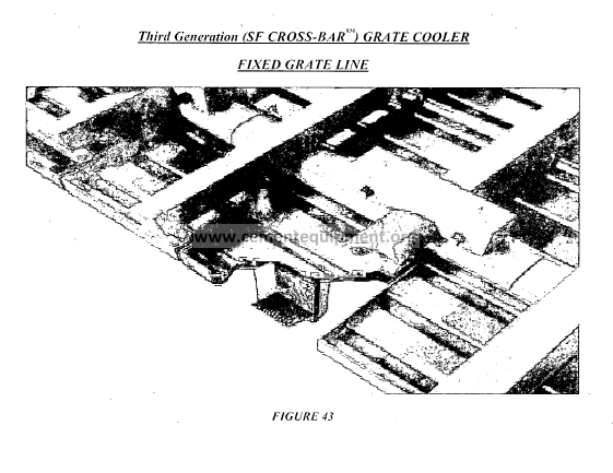
(c) Separate Clinker Conveying System
As originally introduced, there were two types of cross bars: stationary and
movable. The stationary and movable cross bars alternated the same as
stationary and movable grate rows alternate in conventional coolers as shown
in FIGURE 43. The movable cross bars are driven by a drive plate. The
drive plate is attached to a movable frame.
Unlike the movable frame used in a conventional grate cooler, the frame does
not support any grate plates or their support beams. Quite simply, there are
no movable grate plate supports. As a result, a much more simple design of
movable frame is employed. This allows a simple system oflinear bearings
to be used.
The cross bars are attached to the drive plate by a retainer bracket that
attaches to ears extending from the drive plate. The retainer bracket and cross
bars are locked by wedges driven in by hammer. Replacement of the cross
bar is simply made by knocking the wedges out with a hammer and removing
the retainer bracket.
Spillage is prevented from entering the plenum chamber by a series of
sealing profiles. The sealing profiles combine to form a labyrinth type seal
that prevents undergrate spillage. Since the grate plates do not move, it is
possible to make a very effective seal between the stationary air distribution
system and the moving drive plate. Each module has a hydraulic cylinder
located in the under-grate chamber that imparts a reciprocating motion to the
movable frame that is parallel to the grate-line. When modules are installed
end-to-end, the movable frames ofeach module are connected in such a way
that they move in unison. Modules installed side-by-side do not have their
movable frames connected. In other words, a module positioned alongside of
another module may be stroking rearward while the other module is stroking
forward. In addition, their speeds could be different.
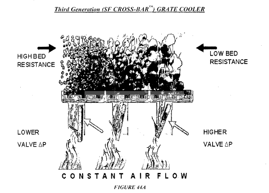
(d) Air Distribution Plates with Mechanical Flow Regulators
The heart of the “cross-bar” cooler is its unique and patented air distribution
system. Each air distribution plate consists ofa stainless steel top section that
looks similar to a pocket-style Controlled Flow Grate (CFG) plate.
On the bottom of each individual plate is a rectangular tower containing a
weighted Mechanical Flow Regulator (MFR). Depending upon the pressure
inside the tower, the regulator opens or closes. Because the pressure inside
the tower is an exact measure of the resistance ofthe material layer above it,
the regulator opens to compensate for an increase III the “measured”
resistance or closes to compensate for a decrease III the “measured”
resistance. The MFR, thus, controls the amount ofcooling air that flows from
the under-grate chamber into each individual air distribution plate as seen in
FIGURE 44A.
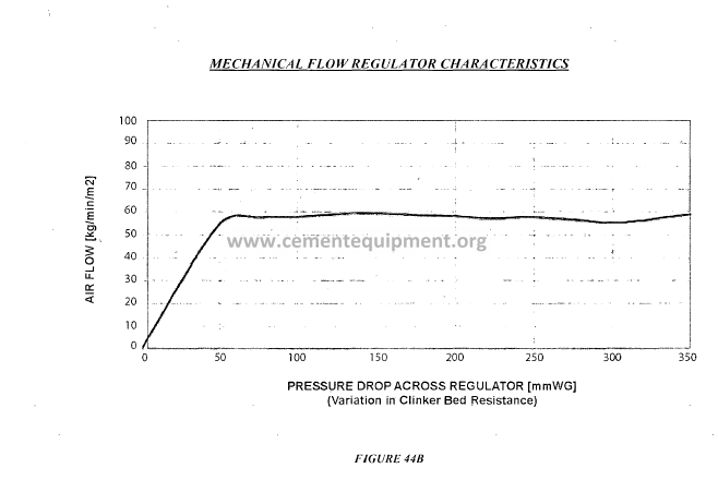
The regulators are specially designed to maintain a constant air flow through
the air plate and the clinker layer, irrespective of the clinker bed height,
particle size distribution, temperature, etc. In his way, every air plate in the
cooler is provided with the quantity of cooling air that it needs.
The MFR consists ofa special orifice plate which hangs from the tower. The
hanging plate acts as a variable orifice that moves relative to the difference in
pressure on either side of the plate. The regulator, therefore, only introduces
a pressure drop through it self in the event that the resistance of the clinker
layer is below normal.
This is in contrast to second generation “air beam” grate plates which
introduce a constant pressure loss for a given air volume. Normally, a
pressure loss of at least 200 mm WG is required to normalize differences in
the clinker layer in order to ensure uniform distribution of cooling air.
With the self regulating mechanical flow device, it is possible to obtain
constant air-flow through the clinker layer without paying for the required
pressure loss of200 mm WG. This, coupled with higher thermal efficiency,
results in a power savings compared to modern air-beam coolers.
Cooling air is supplied to the under-grate chamber of each module by fans
equipped with piezometers. The mechanical flow regulators are so effective
that the required number offans is typically only determined by the number
of modules set end-to-end. That is, modules set side-by-side have their
undergrate chambers joined so that only one fan supplies air to both the right
and left. For example, the a 3×5 “cross-bar” Cooler for 3600 tpd is equipped
with a total of only 6 cooling fans even though it is a triple-wide modular
cooler. It has one fan for the “Controlled Impact Module” plus one fan for
each ofthe five cross bar modules in length. The regulator used in each grate
plate is designed for a specific air-flow rate as shown in FIGURE44B. The
regulator design is varied (along the cooler’s length) to .compensate for
changes in the resistance of the clinker layer as the clinker temperature
decreases. For example, it is possible to employ a higher specific air-flow to
the air plates at the inlet to the cooler simply by using one regulator design
over another. It is also possible to vary the regulator design across the width
of the cooler. For example, “Zero Flow” regulators may be used along both
sides of the cooler within the “Stationary Impact Module” as a means to
compensate for non-uniform distribution ofclinker across the cooler’s width.
2. Further Improvements/Developments of Third Generation Grate Coolers
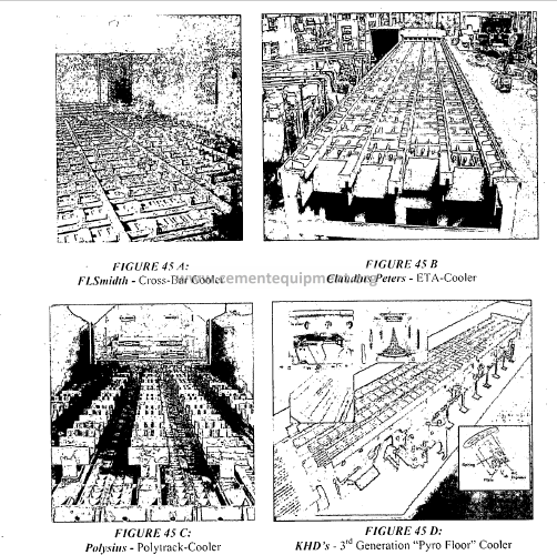
Today, the following 3’d Generation Coolers are available:
• “Smidth-Fuller Cross-Bar Cooler” by FLSmidth (FIGURE 45A)
• “Eta Cooler” by Claudius Peters (FIGURE 45B)
• “Polytrack Cooler” by Polysius (FIGURE 45C)
• “Pyro Floor Cooler” by KHD (FIGURE 45D)
In addition, a multi-moveable version of the original “cross-bar” cooler is
now available called the “Multi-Movable” Design which provides all of the
benefits previously afforded by “the cross-bar” cooler in addition to the
following features:
• Increased Transport Efficiency to Allow Horizontal Installation
• Flexibility for Retrofit Situations
• Fewer Wear Parts
• Even Higher Reliability
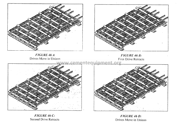
The increased transport efficiency is accomplished by “removing” the
stationary bars from the original “cross-bar” design and revamping the
moveable bars. The moveable bar transportation mechanism was modified as
follows:
• All drives move in unison in the forward flow direction (FIGURE
46A)
• The “first” drive retracts while the “second” drive acts as a
“stationary” bar (FIGURE 46B)
• The second drive retracts while the first drive acts as a “stationary”
bar (FIGURE 46C)
• The mechanism is repeated (FIGURE 46D)
This subtle change in the drive mechanism has significantly increased the
transport efficiency such that a horizontal grate line is possible for coolers
equipped with the multi-moveable design.
Additionally, the multi-movable technology was specifically designed with
an eye for retrofits. As such, the known dimensions of traditional and airbeam
style coolers have been targeted to design the various cassettes for the
multi-moveable cooler. A multi-moveable cooler cassette is designated with
the width based on grates and supporting beam and the length based on
grates. The cassette configurations cover the following ranges:
• Width: 6, 7, 9 and II Grates
• Length: 12 or 16 Grates
To support partial retrofits of existing coolers, such as the recoup zone, a
special outlet transition has been designed such that the multi-moveable
technology mates to the existing grateline. In this way, the cement producer
can stage the replacement of the entire cooler over a couple of years or they
can simply limit the retrofit to the area that provides “the most bang for the
buck” (i.e. – recoup zone).
With the enormous flexibility in width, length, and transition; a large number
of existing coolers can be retrofitted inside the existing box with the multimoveable
technology. In addition to retrofitting existing coolers, complete
new cooler constructions can be installed with the multi-moveable
technology. As with the original “cross-bar” cooler’s modular approach, the
cassettes of the multi-moveable can be set side by side and end to end to
make up the entire new or retrofit cooler. Through the utilization of 3D
drawing programs and parametric design, the optimal configuration of
cassettes can be utilized to tailor the multi-moveable cooler to any plant.
It is anticipated the multi-moveable technology will be highly reliable,
maintain a high level of thermal efficiency, and further reduce the
maintenance costs of clinker coolers since the number of wear components
has been reduced. With the increase in transport efficiency and the reduction
of wear parts, it is estimated that the wear components will now last up to
three years before they will require changing. As such, it is estimated that
the average annual parts price for a 10 year period will be further reduced 25
– 50% from the expected figures on the original “cross-bar” cooler.
The increased transport efficiency makes it practical to install the “MultiMovable”
design horizontally instead of on, for example, a 3 to 5 degree
slope. By means of comparison, FIGURE 47 presents an elevation view for
both an original “cross-bar” cooler and the new multi-movable design.
Importantly, ‘bull nose’ velocities through the cooler throat are critical to the
success ofthe cooler operation (e.g. to minimize dust circulation), especially
for this specific retrofit solution presented by FIGURE 47 in which the
existing clinker cooler was of the reverse flow variety (i.e. – it went back
underneath the kiln). As shown in FIGURE 47 A, in the case of a sloped
cooler, the space constraints to maintain proper velocities would have
normally required digging a pit at the cooler discharge area which was not an
attractive option for the cement producer as it would require extra time and a
significant amount of additional money for the modernization. In contrast,
the horizontal installation of the new multi-moveable cooler allowed the
proper velocities within the system to be maintained while building the new
cooler on the existing foundation. In this case, it was originally foreseen to
reuse the existing cooler sideframes; however, due to the very poor condition
ofthe sideframes and roof, it was decided to go for a completely new cooler.
The multi-moveable cooler was built in a manufacturing shop, shop tested,
and shipped to site in modular cassette form to maintain the workshop
quality. Arriving early onsite, there was ample opportunity to conduct a
certain level ofpreassembly prior to the major outage. During the outage, the
old cooler was completely removed and the new multi-moveable cooler was
lifted and slid into place on the existing cooler foundation .. The installation
ofthe cooler was part ofan overall plant wide upgrade. Refer to FIGURE 48
for pictures from the preassembly, installation, and final assembly at the
plant.
3. Third Generation Grate Cooler Performance
Third generation coolers have shown a Standard Cooler Loss corresponding
to 80 to 95 kcal/kg. In comparison, air-beam grate coolers typically have a
Standard Cooler Loss of90 to 120 kcal/kg. This means that the heat recovery
is extremely high for the cross-bar type of clinker cooler.
Improved thermal efficiency of the cross-bar cooler is made possible by the
following design features:
• Inefficient sealing air is not required.
• Clinker fall-through is completely avoided.
• The grate-line is completely stationary, so no gaps exist for possible
short-circuiting of cooling air.
• The clinker conveying system and clinker cooling systems are
completely independent therefore cooling efficiency does not
deteriorate over time.
• The MFR system (a separate air flow regulator for each grate plate) is
used throughout the entire cooler (not just the inlet section and not
just the recuperation zone of the cooler).
• The regulationvalves ensure that each plate in the cooler is provided
with the quantity of cooling air that it needs regardless of process
conditions.
FIGURE 49 presents a typical cooler balance for a cross-bar type cooler. As
shown, significant improvements can be gained compared to “modem” airbeam
coolers.
IV. COMPARISON OF FIRST, SECOND AND THIRD GENERATION
COOLER PERFORMANCE
FIGURE 50 presents comparative process efficiencies for each type of cooler:
• Conventional Grate Cooler (First Generation)
• Hybrid (Air-Beam/Conventional Grate) Cooler
• Air-Be.am Cooler (Second Generation)
• Modem Grate Cooler (Third Generation)
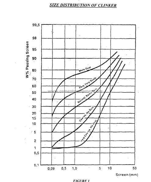
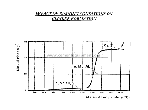
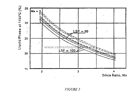
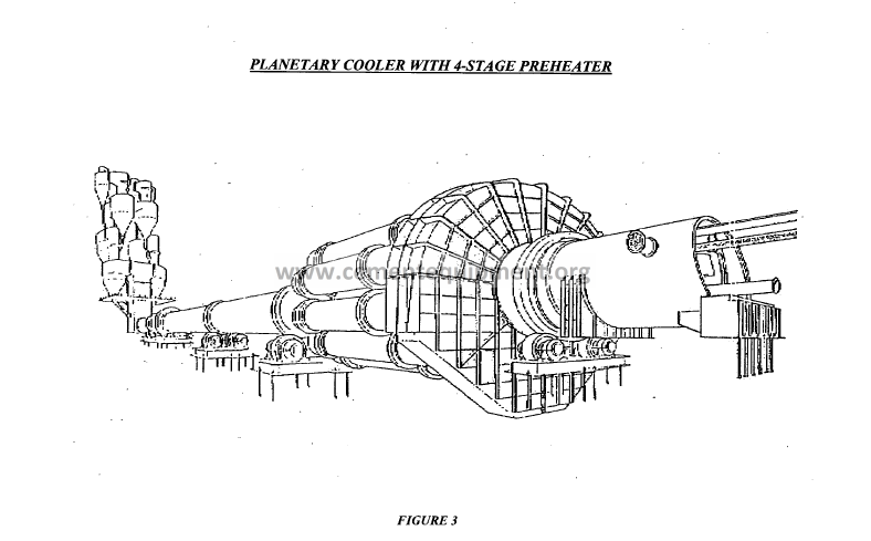
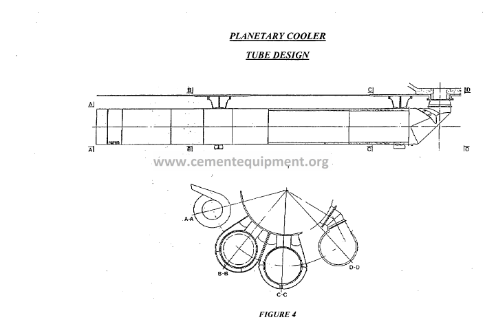
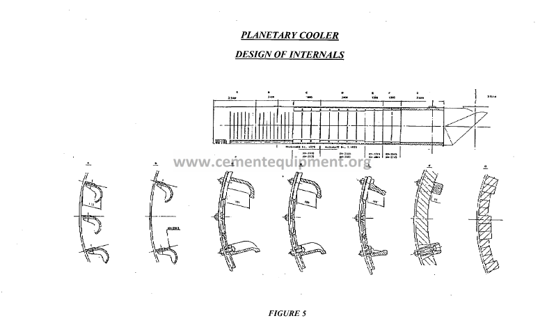
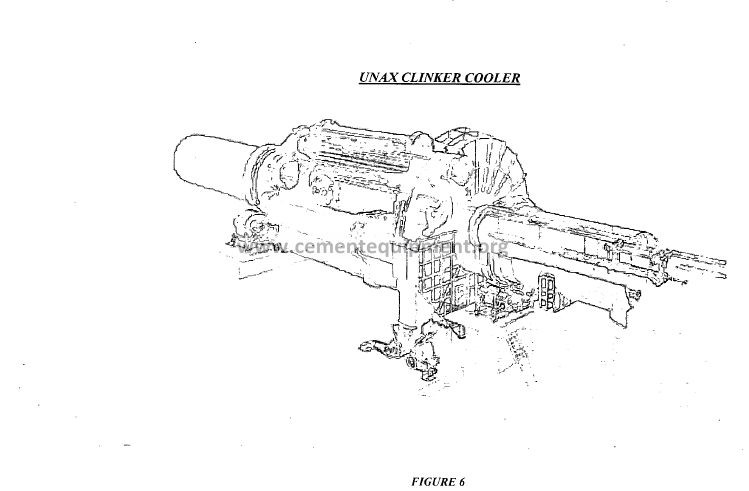
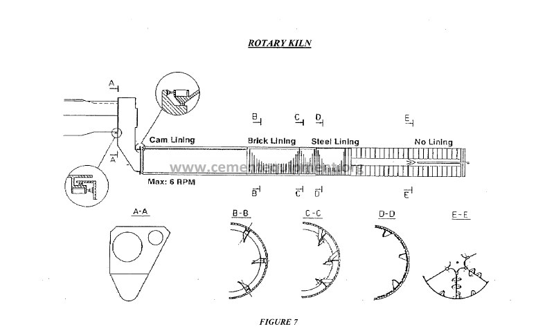
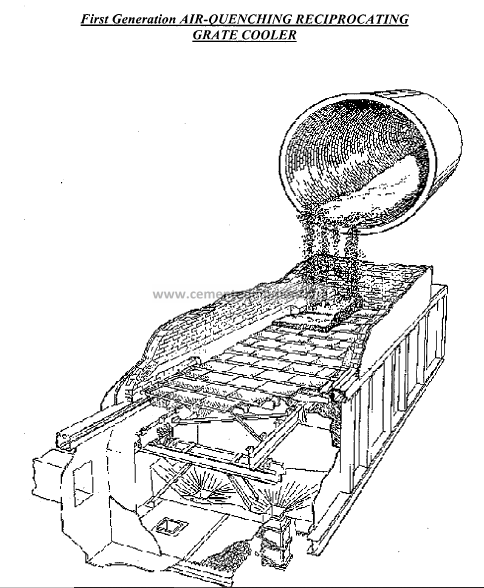
GRATE COOLER
ADVANTAGES
ABILITY TO HANDLE lARGE
CAPACITIES
CAPABLE OF ACHIEViNG lOW CLINKER
TEMPERATURES
FAVORABLE HEAT RECUPERAr~ON
PERMITS TAKE-OUT OF HOT TERTIARY
AIR
GREATEST POTENTIAL FOR
DEVELOPMENT
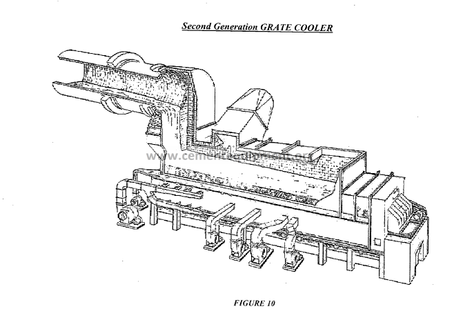
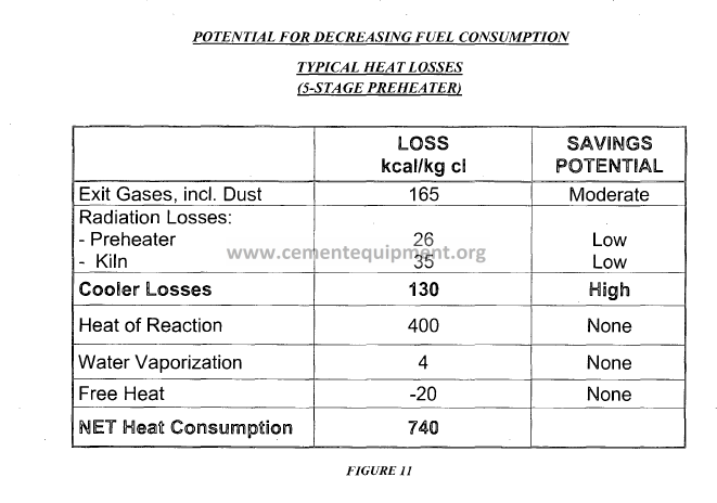
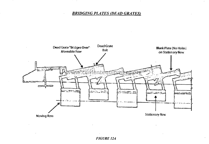
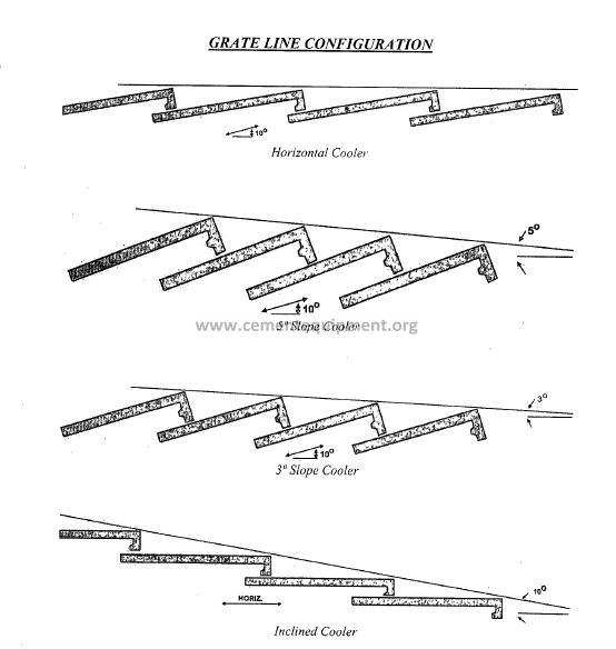
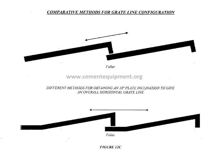
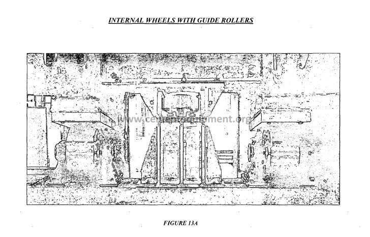
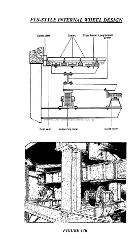
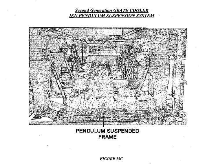
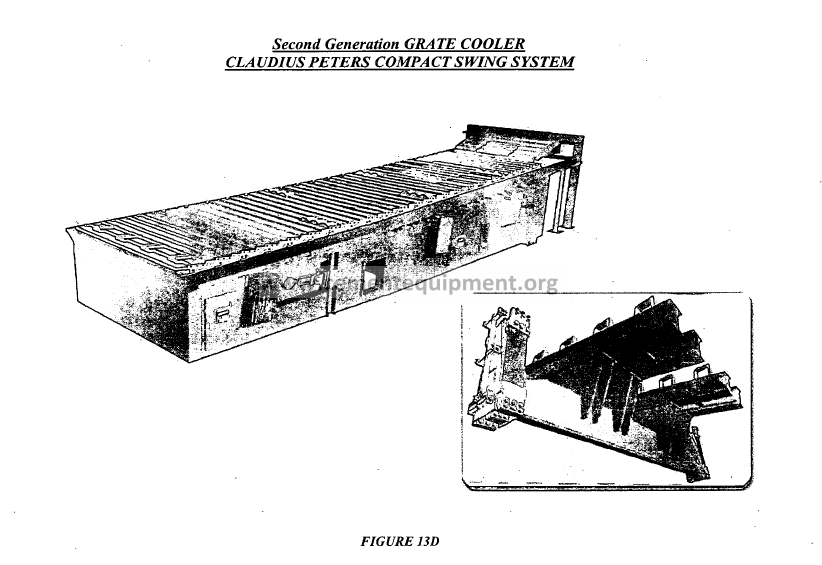
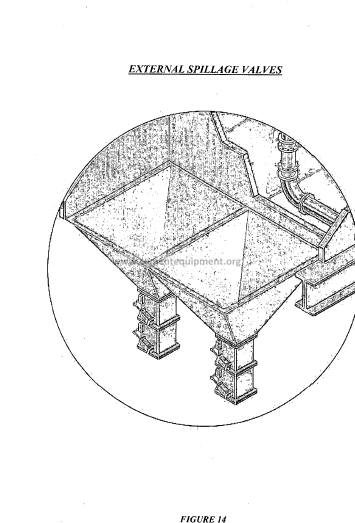
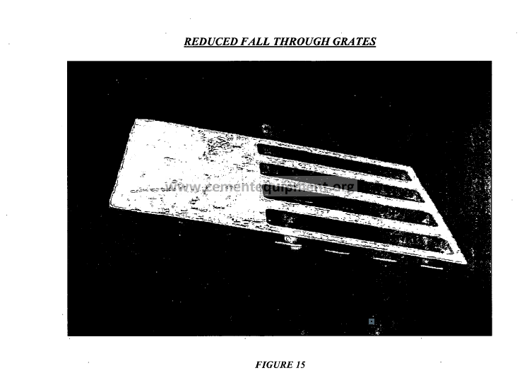
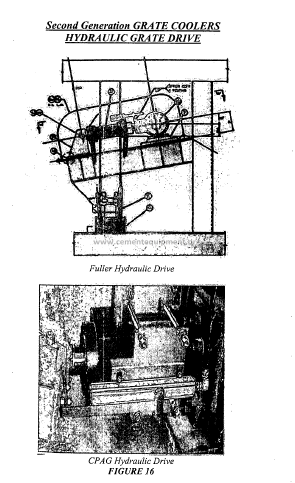
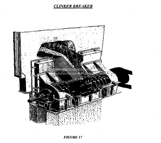
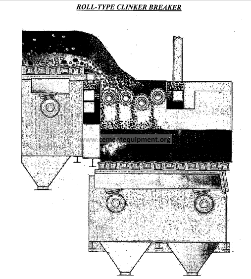
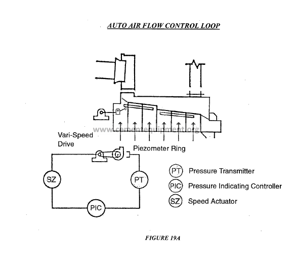
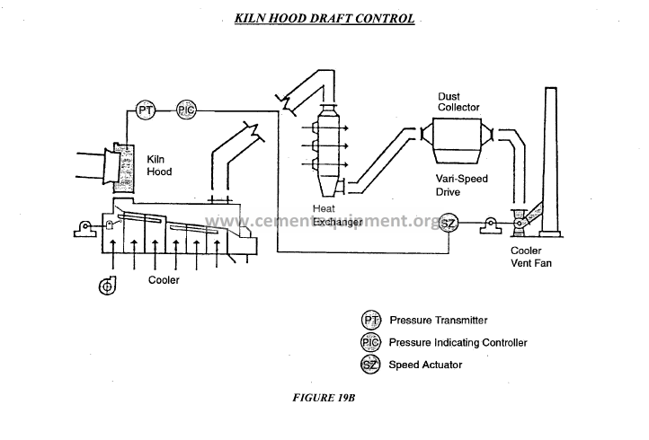
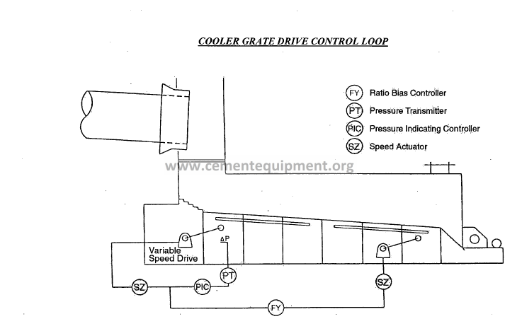
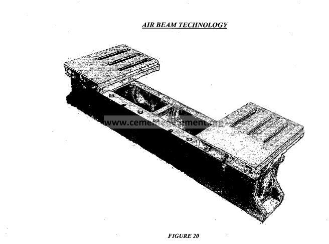
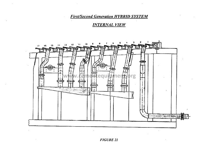
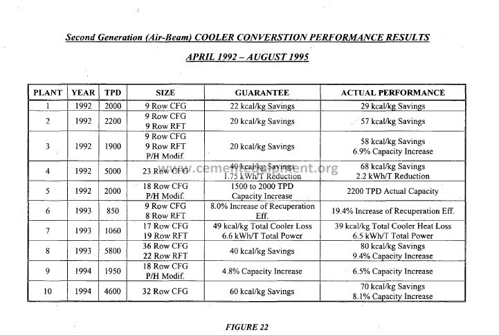
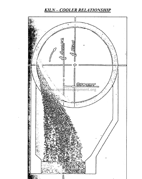
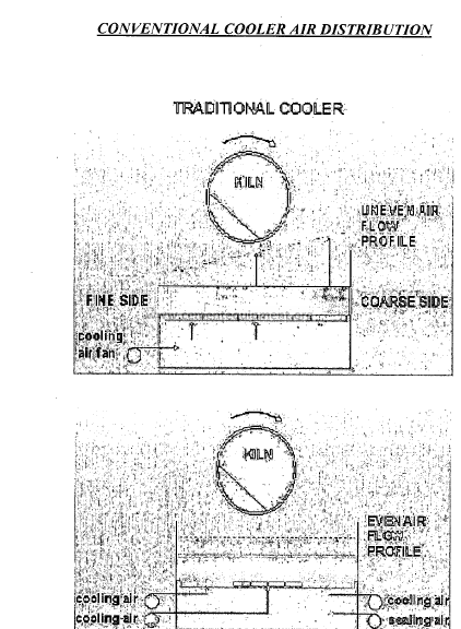
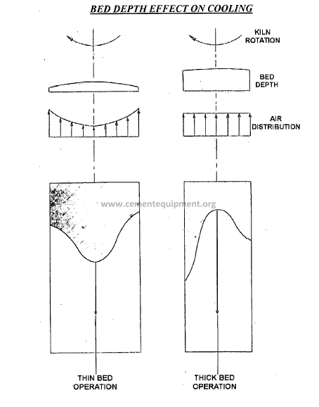
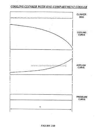
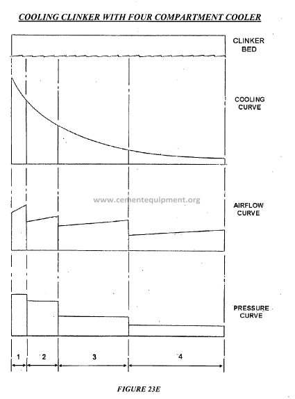
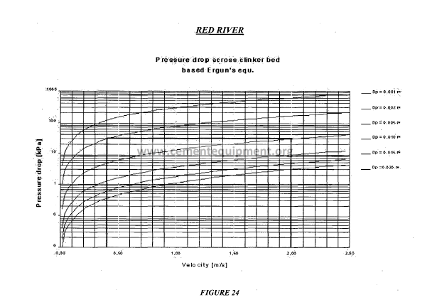
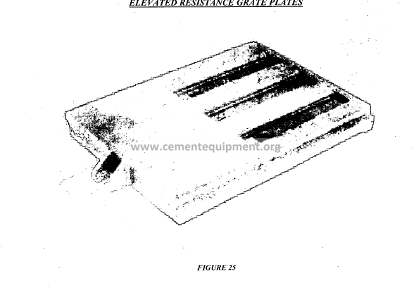
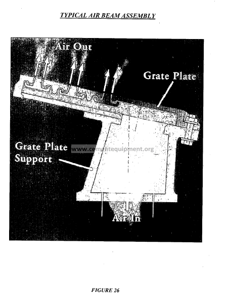
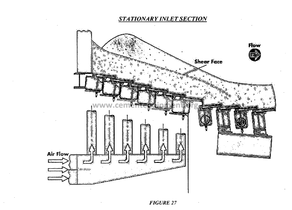
COOLER LOSS
• HEAT LEAVING THE COOLER AS
SENSIBLE HEAT WITH THE CLINKER
• HEAT LEAVING THE COOLER WITH THE
EXCESS AIR
• HEAT LEAVING THE COOLER AS
RADIATION
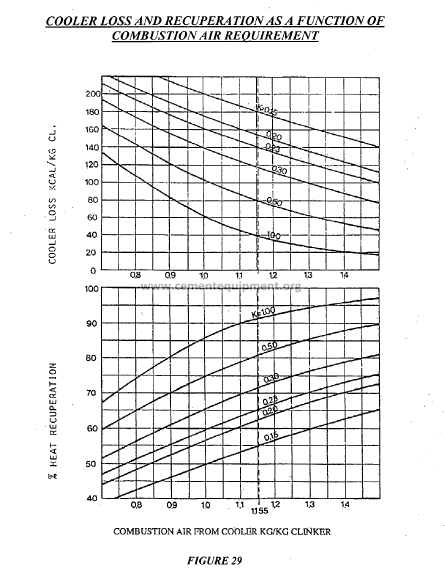
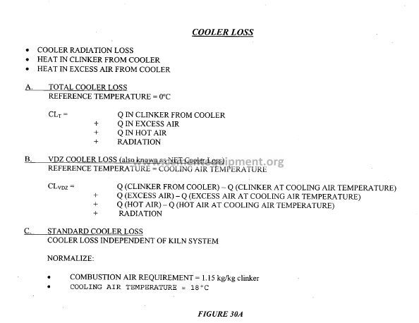
COOLER EFFICIENCY
A. The cooler efficiency to be defined and calculated as follows:
![]()
Where:
100 x Cooler Loss. %
1450 X SK1450 + (Mc A X TCA X SATCA )
Cooler Loss = TKO XSKTKO + MEX XTEX XSATEX+ RA
MCA = kg of cooling air per kg of clinker
MEX = kg of excess air per kg of clinker
TC = temperature ambient (of cooling air)
TEX temperature of excess air
TKO temperature of clinker leaving the cooler
SAT = specific heat of air at temperature T”C
SKT = specific heat of clinker at temperature TOC
RA = cooler housing radiation in kcal/kg of clinker
Reference Temperature = O°C
B. VDZ Cooler Efficiency
Reference temperature = cooling air temperature
E =100 _ 100 x (Cooler Loss – Fan Power)
voz Maximum Heat Release Clinker
Where:
Maximum Heat Release is defined as the heat content of clinker at the kiln discharge
temperature (arbitrarily defined at a temperature rangingfrom 1350°C to l450°C) minusthe
heat content of clinker at the ambient temperature .
C. . Nominal cooler recuperation reference temperature = O°C
![]()