Contents
Everything you need to know about Water Management
[wpecpp name=”package” price=”75″ align=”center”]
by Fred W. Cohrs*
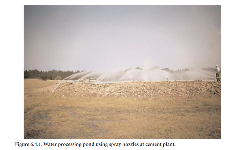
With the change to predominantly dry process clinker manufacturing technology, the water usage of cement plants has been substantially reduced compared to wet process technology. Water is still necessary, however, for non-contact cooling of drives, bearings, air compressors, air conditioners, and various probes in hot process stages as well as hot gas streams, both in the pyro-processing system and cement grinding mills. The efficiency of water circulation, retention, and recycling becomes paramount in areas of water scarcity. A water retention, processing, and recycling pond at a cement plant in the United States is shown in Figure 6.4.1.
ENVIRONMENTAL ISSUES
In the permitting stage for a new cement plant, water consumption can become a significant issue, particularly in arid areas for reasons of availability, or in areas with high water tables, where ground water (aquifer) contamination may be a concern. Water returned to the aquifer at elevated tempera-tures or the possibility of its contamination with lubricants or chemical additives used in cement could become a matter of much controversy. Regulators responding to public concern may prohibit the use of open circuit cooling systems, where the cooling water is returned to its source.
COOLING WATER SYSTEM – CASE STUDY
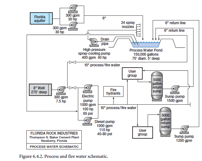
The cooling water system at the Thompson S. Baker Cement Plant, Newberry, Florida, U.S.A. will be used in this chapter as a case study in dealing with water management. Environmentalists and neighbors vigorously opposed the construction of this plant. Prior to letting water become another issue of distorted debates with the opponents, it was decided to design a plant with zero water discharge and minimum water consumption. These intentions were well publicized but did not stop the protesters from predicting disastrous consequences, including depleting the water supply and totally contaminating the water resources in northern Florida. Figure 6.4.2 illustrates the water schematic for the plant.
Permitting
The State of Florida, through its water management districts, is responsible for the quantity of water allowed to be withdrawn and consumed. Our application to pump 750 liters/minute (LPM) or 3.8 million liters/year, equivalent to 200 gallons/minute (GPM) or 1 million gallons/year, was promptly approved. Compared to municipal and agricultural consumption, this amount of water is insignifi-cant and was based on the projected need for 3330 LPM (880 GPM) cooling water, of which 602 LPM (159 GPM) were lost through evaporation.
This permitted loss (use) occurs only when all water users are simultaneously consuming the peak amount. The permitted consumption was considered to be quite adequate over a period of one year, as it was unlikely that the calculated nominal quantities would be needed at all times, given that the plant was unlikely to be operating at full capacity during all available hours.
System Design
Even though fires are extremely rare in cement plants, particularly the type that can be fought with water, we agreed at the outset to install fire hydrants on 152-m (500-ft) centers. Both the insurance underwriter and the local fire department were consulted while designing the system.
At 275 kPa [40 pounds per square inch (PSI)] line pressure, the fire department required a pipe diameter of 250 mm (10 in.) to feed two pumpers simultaneously at a flow rate of 1100 LPM (300 GPM) each.
As the need for an exclusive use of a fire water line appeared to be remote, it seemed that a separate process water system would be an expensive redundancy. It was therefore decided to combine the fire and process water supply lines.
It was concluded that the fire water supply line could be located to serve its intended purpose as well as have sufficient capacity to supply the necessary process water. Process water tabs were located as required.
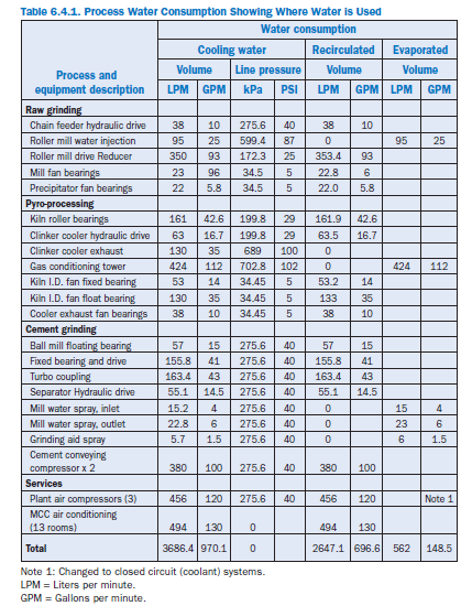
The remaining design task was therefore to size all necessary branches to provide evaporative and non-contact cooling. Each branch line had to be capable of delivering 200% of the specified maxi-mum requirement. Table 6.4.1 shows the process water consumption for the plant.
Source of Water
The plant site is on top of the Florida aquifer. During the design phase, the water table was at 14 m (45 ft) elevation relative to National Geodetic Vertical Datum (NGVD), or 11 m (35 ft) below the lower plant site elevation.
Just outside the fence line of the 0.18 km2 (46 acres) zoned for the plant location are two abandoned mine pits in which the aquifer is exposed. Open aquifers are receptacles for ground water contami-nation and are watched carefully by regulators and environmentalists. One of the pits was selected to provide the plant process and fire fighting water. The no-discharge permit prohibits the return of any water to its source. Spent cooling water is not allowed to reach the aquifer, unless it is first filtered through an approved layer of soil and sand. Percolation tests indicated such a filter system would have to be very large and would be expensive to construct.
A storm water runoff permit was obtained, requiring the construction of 13 remediation ponds. Under the permit, irrigation of the mostly grass-covered plant site was possible, provided the water consumption did not exceed the amount of permitted withdrawal. The irrigation water is taken from the process/fire water line.
The most economical option was therefore to first pump the water from the aquifer into a holding pond of sufficient capacity and return all spent water to this pond. Measurement of water consump-tion, which has to be reported to the state, is made in the supply line to the pond. This provides the record and proof of compliance with the allotted withdrawal rate.
A circular pond was built using an earthen dike, strengthened with a 150-mm (6-in.) riprap cover. The pond was lined with 0.6-mm (24-mil) thick plastic sheets, using taped splices. After three years of operation the plastic liner was replaced with concrete for greater durability and improved heat reflection. Design capacity was for 570,000 liters (150,000 gallons). The pond was expected to be full at all times. Due to its diameter of 23 m (75 ft), the water depth in the pond was only 1.50 m (5 ft). While the large surface area was intended to promote cooling through evaporation, it also soaked up excessive heat during the hot summer months.
Pumps and Pipelines
At the aquifer. Two centrifugal lift pumps with a capacity of 1135 LPM (300 GPM), each mounted on a floating platform, attached to a concrete base, are installed at the edge of the pit. A walkway connects the platform to the shore hinged at both ends. It was anticipated that the water table would vary over time by as much as 2.4 m (8 ft), which determined the length of the walkway. At the time of construction the water table was near its historical maximum elevation. The pumps’ suction lines were sized to lift the water from 7.6 m (25 ft) below the surface, projecting the water temperature to be at least 2.8°C (5°F) lower at that depth than was measured at the surface. The average water temperature at the surface was 25°C (77°F), measured during the 2-year period prior to commencement of the plant construction.
Little information was available to predict the temperature rise of water which circulates through the plant, cooling the numerous bearings and drives. Also, there was no information on the water temperature at reduced aquifer levels. After plant start-up, we found the water temperature of the aquifer to be much greater than projected. As the aquifer level dropped the water temperature rose by 2.8°C-3.3°C (5°F-6°F).
From the aquifer, the water is pumped into the holding pond in which level probes activate the pit pumps. One pump has enough capacity to supply the make-up water. The other pump serves as standby.
At the process water pond. From the bottom drain of the pond, the water flows to a 3785 LPM (1,000 GPM) electric-powered pump, which fills the 250-mm (10-in.) combination process/fire water line under 550 kPa (80 psi) pressure.
As the site offers no means to return water to the pond by gravity flow, two process water return tanks, each capable of holding 19,000 liters (5,000 gallons) were constructed. One tank was located near the cement mill building and one near the kiln drive pier. Each pit is equipped with a 2840 LPM (750 GPM) sump pump, which return the water to the pond through separate 150-mm (6-in.) lines.
The outlets for the return lines at the pond were equipped with nozzles, designed to create a spray to enhance water cooling.
Assurance of Water Availability to Fight a Fire
Concerns were raised during the design phase that water would not be pumped through the supply line during a simultaneous firefighting and electric power outage event. The initial answer was the installation of a water tank on top of the clinker silos, 525 m (170 ft) above ground elevation. One 250-mm (10-in.) pipe was to connect the tank with the main line, both for filling and drainage. During a power failure, the electrically controlled check valve at the base of the silos would have opened to let the tank contents drop into the main water line. This would have provided sufficient cooling water for an orderly shutdown, to avoid destruction of the main kiln burner and the I.D. fans. The plan was discarded in favor of installing a diesel powered standby pump, as it offered the additional assurance of providing water in case of outage of the main process water pond pump. This also eliminated the need for a second (standby) electric pump. The diesel-operated pump has the same capacity as the electric pump.
Initial Operating Experience
While the plant was under construction, Florida underwent a severe drought and the aquifer water level dropped to a multiyear low. The pump suction pipe came to rest on the floor of the aquifer pit and sucked limestone fines along with an inadequate amount of water. The valve stem was immedi-ately reduced by 4.6 m (15 ft). Then the pump functioned well to fill the pond.
Upon plant start up, only minor corrections and modifications in the piping system were required; otherwise the system functioned as designed.
After several months of operation, various shortcomings became apparent. The most troubling of all was the temperature rise of the circulation water.Instead of the projected 35°C (95°F) maxi-mum, the temperature actually rose to 46°C (105°F). In part, this was due to the less than calculated water evaporation for exit gas cooling and an increase in water temperature in the aquifer. The first detrimental result of the excessive temperature was the shutdown of the water-cooled air condition-ers in the Motor Control Center (MCC) rooms.
Water temperature reduction was achieved in two ways: The return pumps were to cause a fine spray at the discharge point of the return lines into the pond with nozzles on each pipe. These nozzles were ineffective with the water pressure generated by the return pumps and did not provide a spray.
The major water consumers listed in Table 6.4.1 did not require the predicted amount of cooling water, resulting in significantly lower water replacement from the aquifer. In fact, the average water replacement (total consumption) was only 380 LPM (100 GPM) on average.
Some relief was obtained by draining water from the pond through the irrigation system. This caused the storm water remediation ponds to fill up and left no room for a storm event.
We then searched for cooler water at lower elevations of the aquifer by drilling a 200-mm (8-in.) well near the process water pond, to a depth of 84 m (275 ft). We installed a 22 kW (30 HP) pump with a capacity of 300 1135 LPM (GPM). Indeed, the water temperature was 2.8°C (5°F) colder and provided some relief. This source had to be abandoned, due to an excessive amount of silt pumped from this depth.
To obtain further reduction of water temperature, a fountain was installed on a float in the center of the pond. The fine spray caused evaporation and cooling. It dropped the temperature 2.8°C (5°F).
It was not enough. The pond temperature continued to exceed the tolerable limit of the air condi-tioners and the hydraulic drives. The plant suffered a number of shutdowns. Plant operations were made somewhat tolerable by amply irrigating the freshly planted lawns and by filling the storm water remediation ponds. The bleed-off shortened the residence time of the water in the process water pond and provided a greater rate of water replacement. As the ambient temperature dropped at the end of the summer, the system functioned normally.
A solution had to be found to drop the water temperature to no higher than the highest ambient summertime temperature.
A more effective water spray system at the process water pond was designed and installed. The new system consisted of a new drain for the pond to a high-pressure pump and a new pipe ring around the top of the pond dike. Twenty five nozzles were affixed to the pipe to discharge a fine spray of water across the pond (Figure 6.4.1). The pump circulates 60% of the return water and drops the pond water temperature to 29°C (85°F) during the hottest time of the summer. This modification finally satisfied the requirement of all temperature-sensitive cooling systems. A lattice-style cooling tower was also evaluated but was predicted to be less effective than the water spray.
Complicating the already frustrating temperature problem was the hardness of the water. Appropriate chemical treatment was provided by qualified contractors, which did not stop the frequent build up of lime deposits in the cooling coils of the plant air compressors. Loss of plant air had reverberating consequences throughout the plant, resulting in substantial loss of production.
To attempt a reduction of the excessive lime content of the water, the process water pond was drained and scrubbed during every kiln outage. This necessitated the shutdown of all equipment requiring water cooling, including the cement grinding system.
Necessary System Modifications
After two complete annual operating cycles, the remaining weaknesses of the water system had been identified and a plan of corrective action was initiated.
Only the plant air and cement pump compressors, all located in the same room, continued to be a problem, primarily due to lime coating of the cooling tubes.
No effective chemical treatment was found to keep the plant air compressor cooling coils from foul-ing. Weekly cleaning with harsh acid treatment was needed to keep the compressors functioning.
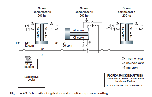
The solution was to disconnect the compressors from the process water-cooling system. A self-contained coolant-based air-cooled system took its place. The flow diagram of a typical closed circuit system is shown in Figure 6.4.3.
SUMMARY
Environmental concerns for excessive water consumption or potential water contamination have prompted us to design a non-discharge process water-cooling system in combination with a fire hydrant water supply. The start-up of this system was expensive due to additional capital costs and lost production. The temperature of the circulating water exceeded the projections and the hardness of the water increased excessively due to less than expected water losses and from forced evapora-tion in the process water pond. Lime fouling of the air compressor cooling tubes decreased their efficiencies and led to plant outages. A closed-circuit air-cooled coolant-based system was installed to solve the problem.
As initially built, the no-discharge process/fire water circulating system met the environmental and quality requirements, but failed the operating needs in certain areas of the plant. A closed-circuit coolant-based cooling system is recommended, however, where excessive temperature and frequent fouling of cooling tubes will shut down certain critical equipment, i.e. air compressors.
The balance of cooling requiring large quantities of water can be adequately accomplished with a combination closed-circuit process/fire water circulating system as installed at the Thompson S. Baker cement plant in Newberry, Florida, U.S.A.
Such an approach would meet the demand for water conservation and water discharge quality, as well as providing greater assurance of reliability of critical equipment, which fails to operate at an elevated temperature.