Contents
Everything you need to know about Energy Efficiency Improvements
[wpecpp name=”package” price=”75″ align=”center”]
by Ernst Worrell*, Christina Galitsky*, and Garth J. Hawkins**
The production of cement is an energy-intensive process that results in the emission of carbon dioxide (CO2) from both the consumption of fuels (primarily for the kiln) and from the calcina-tion of limestone. The high energy intensity makes energy costs an important part of the total production costs for a cement plant. In addition, the U.S. manufacturers face an increasingly competitive environment, and seek out opportunities to reduce production costs without nega-tively affecting the yield or the quality of the product. Energy-efficient technologies often address both aspects, increasing the productivity and achieving future or current environmental goals, thus reducing the regulatory “burden.” End-of-pipe solutions are often expensive and inefficient while energy efficiency can often be the cheapest alternative to reduce pollutant emissions. This chapter examines over 40 energy efficient technologies and measures and estimated energy savings for each of the measures.
ENERGY USE AND CARBON DIOXIDE EMISSIONS IN THE U.S. CEMENT INDUSTRY
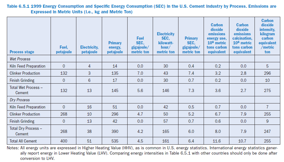
Based on the 1999 United States Geological Survey data, the U.S. cement industry consumed 450 petajoules (1 PJ = 1015 Joule) of final energy (about 2% of total U.S. manufacturing energy use) and emitted carbon dioxide emissions equivalent to 22.3 million metric tons of carbon1 (about 4%of total U.S. manufacturing carbon emissions). Table 6.5.1 provides an estimate of energy con-sumption by process step in the U.S. cement industry. The estimates are based on the throughput of the different processes, energy consumption information provided for the different processes, and the total energy consumption in the U.S. cement industry in 1999.
Energy consumption in the U.S. cement industry declined between 1970 and 1999. Primary energy use decreased at an average of 0.3% per year, from 586 PJ in 1970 to 540 PJ in 1999, although production increased over that time span. The share of the two main clinker-making processes in energy consumption changed significantly between 1970 and 1997. While the wet process consumed 62% of total cement energy consumption in 1970, it used 27% in 1999, while energy consumption of the dry process increased from 38% of total cement energy consumption in 1970 to 71% in 1999, with the remainder consumed by plants classified as either.
While per unit emissions have decreased, total carbon dioxide emissions from fuel consumption in the cement industry in 1999 were virtually back at the level of 1970 at around 11.9 MtC, despite a drop in the years in between. Carbon dioxide emissions from clinker calcination increased from 9.3 MtC in 1970 to 10.7 MtC in 1999 due to the increased clinker production. Hence, total carbon dioxide emissions from the cement industry increased to 22.6 MtC (including emissions from power generation). Carbon dioxide emissions from fuel consumption have decreased with energy consumption, and shifting fuel use patterns have affected carbon emissions significantly as well. From 1970 to 1999 the primary energy intensity fell from 8.5 GJ/ton in 1970 to 6.2 GJ/ton in 1999 per the USGS data. Energy intensity of cement production decreased due to increased capacity of the more energy efficient dry process for clinker-making, energy efficiency improvements in exist-ing plants and reduced clinker production per ton of cement produced.
As for the energy intensity trends, there are conflicting results from two studies. The USGS data shows an increasing trend in the energy intensity of the cement industry in recent years. This trend is opposite of the trend provided by data of the Portland Cement Association (PCA) in their annual survey. The PCA survey results show a slightly declining trend in energy intensity over the same period. Both the PCA and USGS datasets on energy use and production trends are very valu-able datasets, certainly when compared to those existing for other industrial sectors in the U.S. Given the different approaches and boundaries between both datasets it is impossible to fully understand the differences found for energy use. The uncertainty of the statistical data on energy is estimated at +/-5%. The main reasons for differences between both datasets can be found in the reporting of waste fuels before 1993, the use of conversion values for the higher (or gross) heating value of the fuels, the reporting in terms of primary energy (including energy losses for power generation for purchased electricity), reporting format for cement and clinker production to esti-mate energy intensity, coverage of the industry, and individual errors in the surveys.
Total carbon dioxide emissions (including emissions from limestone calcination for clinker-making) decreased at 0.3% per year, on average, from 305 kg C/ton in 1970 to 255 kg C/ton in 1999. The specific carbon dioxide emissions from both the wet and dry processes decreased between 1970 and 1999, the wet process at an average of -0.01% per year and the dry process at an average rate of -0.6% per year. The increased dry process clinker production capacity, improved energy efficiency, and decreasing clinker/cement-production ratio reduced the specific carbon dioxide emissions, while the substantial fuel shifts towards more carbon intensive fuels like coal and coke contributed to an increase in specific carbon dioxide emissions. Overall, fuel mix trends were more than offset by energy intensity reductions, leading to an overall decrease in specific carbon dioxide emissions.
Internationally, the cement produced in the U.S. has a relatively high carbon intensity, expressed as emissions per ton of cement produced. This is due to the high share of portland cement (e.g., a high clinker to cement ratio), high energy-intensity (e.g., high share of the wet process for clinker production) and the large use of coal as fuel in cement kilns and power production.
ENERGY EFFICIENCY TECHNOLOGIES AND MEASURES
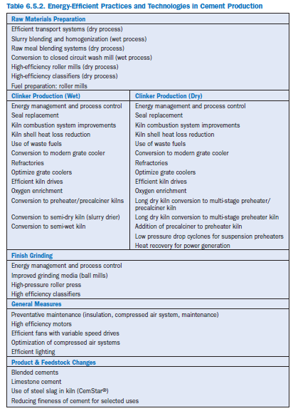
Several technologies and measures exist that can reduce the energy intensity (i.e., the electricity or fuel consumption per unit of output) of the various process stages of cement production. This section provides more detailed estimates on the technologies and measures, and potential for implementation. Table 6.5.2 lists the technologies and measures for dry and wet process plants. Not all measures will apply to all plants. Applicability will depend on the current and future situa-tion in individual plants. For example, expansion and large capital projects are likely to be imple-mented only if the company has about 50 years of remaining limestone reserves onsite. Plants that have a shorter remaining supply are unlikely to implement large capital projects, and would rather focus on minor upgrades and energy management measures.
Although technological changes in equipment can help to reduce energy use, changes in staff behavior and attitude may have a greater impact. Staff should be trained in both skills and the company’s general approach to energy efficiency in their day-to-day practices.
Personnel at all levels should be aware of energy use and objectives for energy efficiency improvement. Often this information is acquired by lower level managers but not passed to upper management or down to staff (Caffal, 1995). Programs with regular feedback on staff behavior, such as reward systems, have had the best results. Though changes in staff behavior, such as switching off lights or closing windows and doors, often save only small amounts of energy at one time, taken continuously over longer periods they may have a much greater effect than more costly technological improvements. Most importantly, companies need to institute strong energy management programs that oversee energy efficiency improvement across the corporation. An energy management program will see to it that all employees actively contribute to energy efficiency improvements.
Participation in voluntary programs like United States Environmental Protection Agency (USEPA) ENERGY STAR program, or implementing an environmental management system such as ISO 14001 can help companies track energy and implement energy efficiency measures. One ENERGY STAR partner noted that combining the energy management programs with the ISO 14001 pro-gram has had the largest effect on saving energy at their plants.
Energy Management Systems and Programs
Improving energy efficiency should be approached from several directions. A strong, corporate-wide energy management program is essential. Crosscutting equipment and technologies such as compressed air and motors, common to most plants and manufacturing industries, including cement, present well-documented opportunities for improvement. Equally important, the produc-tion process can be fine-tuned to produce even greater savings. Below are some measures concern-ing these and other general crosscutting utilities that apply to the cement industry.
Energy management programs. Changing how energy is managed by implementing an organization-wide energy management program is one of the most successful and cost-effective ways to bring about energy efficiency improvements.
An energy management program creates a foundation for positive change and provides guidance for managing energy throughout an organization. In companies without a clear program in place, opportunities for improvement may be known but may not be promoted or implemented because of organizational barriers. These barriers may include a lack of communication among plants, a poor understanding of how to create support for an energy efficiency project, limited finances, poor accountability for measures or perceived change from the status quo. Even when energy is a significant cost for an industry, many companies still lack a strong commitment to improve energy management.
The USEPA, through ENERGY STAR, works with leading indus-trial manufacturers to identify the basic aspects of an effective energy management program (www.energystar.gov). The major elements are depicted in Figure 6.5.1.
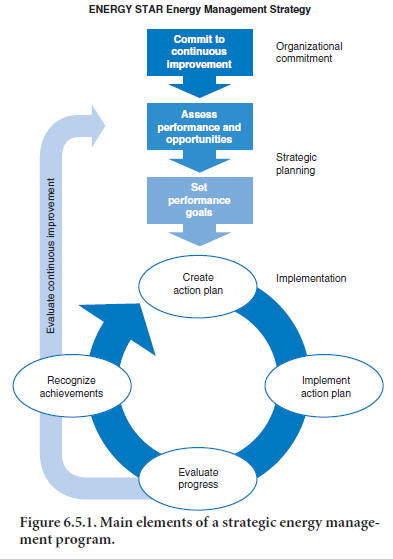
A successful program in energy management begins with a strong commitment to continuous improvement of energy efficiency. This involves assigning oversight and management duties to an energy director, establishing an energy policy, and creating a cross-functional energy team. Steps and procedures are then put in place to assess performance, through regular reviews of energy data, technical assessments and benchmarking. From this assessment, an organization is able to develop a baseline of energy use and set goals for improvement. Performance goals help to shape the development and implementation of an action plan. An important aspect for ensuring the successes of the action plan is involving personnel throughout the organization.
Staff can be trained in both skills and the general approach to energy efficiency in day-to-day prac-tices. Personnel at all levels should be aware of energy use and objectives for efficiency. By passing information to everyone, each employee can save energy. In addition, performance results should be regularly evaluated and communicated to all personnel, recognizing high performers. Examples of some simple tasks employees can do include the following (Caffal, 1995):
• Switch off motors, fans and machines when they are not being used, especially at the end of the working day or shift, and during breaks, when it does not affect production, quality or safety. Similarly, turn on equipment no earlier than needed to reach the correct settings
(temperature, pressure) at the start time.
• Switch off unnecessary lights; rely on daylighting whenever possible.
• Use weekend and night setbacks on HVAC in offices or conditioned buildings.
• Report leaks of water (both process water and dripping taps), steam and compressed air. En-sure they are repaired quickly. The best time to check for leaks is a quiet time like the weekend.
• Look for unoccupied areas being heated or cooled, and switch off heating or cooling.
• Check that heating controls are not set too high or cooling controls set too low. In this situa-tion, windows and doors are often left open to lower temperatures instead of lowering the heating.
• Check to make sure the pressure and temperature of equipment is not set too high.
• Prevent drafts from badly fitting seals, windows and doors, and hence, leakage of cool or warm air.
• Carry out regular maintenance of energy-consuming equipment.
• Ensure that the insulation on process heating equipment is effective.
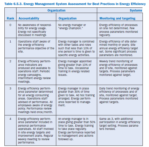
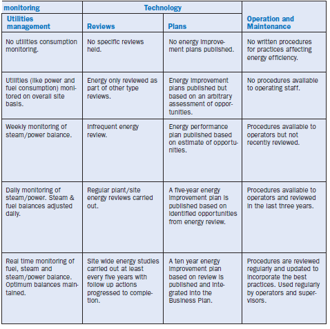
Evaluating performance involves the regular review of both energy use data and the activities carried out as part of the action plan. Information gathered during the formal review process helps in setting new performance goals and action plans and in revealing best practices. Establishing a strong communications program and seeking recognition for accomplishments are also critical steps. Strong communication and receiving recognition help to build support and momentum for future activities. Quick assessment of an organization’s efforts to manage energy can be made by comparing the current program against Table 6.5.3.
Support for a business energy management program can come from outside sources as well. Some utility companies work with industrial clients to achieve energy savings. In these cases, utility personnel work directly with the company onsite.
Energy monitoring systems. The use of energy monitoring and process control systems can play an important role in energy management and in reducing energy use. These may include submetering, monitoring, and control systems. They can reduce the time required to perform complex tasks, often improve product and data quality and consistency, and optimize process operations. Typically, energy and cost savings are around 5% or more for many industrial applica-tions of process control systems. These savings apply to plants without updated process control systems; many U.S. plants may already have modern process control systems in place to improve energy efficiency.
Raw Materials Preparation
Efficient transport systems (dry process). Transport systems are required to convey powdered materials such as kiln feed, kiln dust, and finished cement throughout the plant. These materials are usually transported by means of either pneumatic or mechanical conveyors. Mechanical conveyors use less power than pneumatic systems. Based on Holderbank (1993), the average energy savings are estimated at 2.0 kilowatt-hour/metric ton raw material with a switch to mechanical conveyor systems. Conversion to mechanical conveyors is cost-effective when replace-ment of conveyor systems is needed to increase reliability and reduce downtime.
Raw meal blending (homogenizing) systems (dry process). To produce a good quality product and to maintain optimal and efficient combustion conditions in the kiln, it is crucial that the raw meal is completely homogenized. Quality control starts in the quarry and continues to the blending silo. On-line analyzers for raw mix control are an integral part of the quality control system (Fujimoto, 1993; Holderbank, 1993).
Most plants use compressed air to agitate the powdered meal in so-called air-fluidized homogeniz-ing silos (using 1-1.5 kilowatt-hour/metric ton raw meal). Older dry process plants use mechanical systems, which simultaneously withdraw material from 6-8 different silos at variable rates (Fujimoto, 1993), using 2-2.6 kilowatt-hour/metric ton raw meal. Modern plants use gravity-type homogenizing silos (or continuous blending and storage silos) reducing power consumption. In these silos, material funnels down one of many discharge points, where it is mixed in an inverted cone. Gravity-type silos may not give the same blending efficiency as air-fluidized systems. Although most older plants use mechanical or air-fluidized bed systems, more and more new plants seem to have gravity-type silos, because of the significant reduction in power consumption (Holderbank, 1993). Silo retrofit options are cost-effective when the silo can be partitioned with air slides and divided into compartments which are sequentially agitated, as opposed to the construc-tion of a whole new silo system (Gerbec, 1999). The energy savings are estimated at 0.9-2.5 kilo-watt-hour/metric ton raw meal (Fujimoto, 1993; Holderbank, 1993; Alsop & Post, 1995, Cembureau, 1997; Gerbec, 1999).
Slurry blending and homogenizing (wet process). In the wet process the slurry is blended and homogenized in a batch process. The mixing is done using compressed air and rotating stir-rers. The use of compressed air may lead to relatively high energy losses because of its poor effi-ciency. The main energy efficiency improvement measures for slurry blending systems are found in the compressed air system (see below under plant-wide measures).
Wash mills with closed circuit classifier (wet process). In most wet process kilns, tube mills are used in combination with closed or open circuit classifiers. Replacing the tube mill by a wash mill would reduce electricity consumption by 40%-60% (Cembureau, 1997) at comparable investment and operation costs as a tube mill system.
Use of roller mills (dry process). Traditional ball mills used for grinding certain raw materi-als (mainly hard limestone) can be replaced by high-efficiency roller mills, by ball mills combined with high-pressure roller presses, or by horizontal roller mills. The use of these advanced mills saves energy without compromising product quality. Energy savings of 7 kilowatt-hour/metric ton raw material (Cembureau, 1997) are assumed through the installation of a vertical or horizontal roller mill. An additional advantage of the inline vertical roller mills is that they can combine raw material drying with the grinding process by using large quantities of low grade waste heat from the kilns or clinker coolers (Venkateswaran and Lowitt, 1988). Various roller mill process designs are marketed.
In 1998, Arizona Portland cement (Rillito, Arizona) installed a roller mill for raw material grinding increasing throughput, flexibility, raw meal fineness and reducing electricity consumption (De Hayes, 1999). In North America, it is estimated that over 20% of raw grinding capacity is using roller mills (Holderbank, 1993).
Raw meal process control (dry process – vertical mill). The main difficulty with existing vertical roller mills are vibration trips. Operation at high throughput makes manual vibration control difficult. When the raw mill trips, it cannot be started up for one hour, until the motor windings cool. A model predictive multivariable controller maximizes total feed while maintaining a target residue and enforcing a safe range for trip-level vibration. The first application eliminated avoidable vibration trips (which were 12 per month prior to the control project). The cited increase in throughput was 6% with a corresponding reduction in specific energy consumption of 6% (Martin and McGarel, 2001b).
High-efficiency classifiers/separators. A recent development in efficient grinding technolo-gies is the use of high-efficiency classifiers or separators. Classifiers separate the finely ground particles from the coarse particles. The large particles are then recycled back to the mill. High effi-ciency classifiers can be used in both the raw materials mill and in the finish grinding mill.
Standard classifiers may have a low separation efficiency, which leads to the recycling of fine parti-cles, and results in extra power use in the grinding mill. Various concepts of high-efficiency classi-fiers have been developed (Holderbank, 1993; Süssegger, 1993). In high-efficiency classifiers, the material stays longer in the separator, leading to sharper separation, thus reducing overgrinding. Electricity savings through implementing high-efficiency classifiers are estimated at 8% of the specific electricity use (Holderbank, 1993).
In 1990, Tilbury Cement (Delta, British Columbia, Canada) modified a vertical roller mill with a high-efficiency classifier increasing throughput and decreasing electricity use (Salzborn and Chin-Fatt, 1993). Case studies have shown a reduction of 3-4 kilowatt-hour/metric ton raw material (Salzborn and Chin-Fatt, 1993; Süssegger, 1993). Replacing a conventional classifier by a high-effi-ciency classifier has led to 15% increases in the grinding mill capacity (Holderbank, 1993) and improved product quality due to a more uniform particle size (Salzborn and Chin-Fatt, 1993), both in raw meal and cement. The better size distribution of the raw meal may lead to fuel savings in the kiln and improved clinker quality.
Fuel Preparation
Coal is the most widely used fuel in the cement industry, and the main fuel for the vast majority of clinker kilns in the U.S. Fuels preparation is most often performed on-site. Fuels preparation may include crushing, grinding and drying of coal. Coal is shipped “wet” to prevent dust formation and fire during transport. Most commonly a Raymond bowl mill or a roller mill is used for coal grind-ing, and waste heat of the kiln system (e.g., the clinker cooler) is used to dry the coal if needed.
Other advantages of a roller mill are that it is able to handle larger sizes of coal (no pre-crushing needed) and coal types with a higher humidity, and can manage larger variations in throughput. However, tube mills are preferred for more abrasive coal types. Currently, roller mills are the most common coal mills in the U.S. cement industry. Lehigh Portland Cement installed a vertical roller mill for coal grinding in 1999 at the Union Bridge, Maryland plant. Lafarge cement commissioned a vertical roller mill for the new kiln line V at the Roberta plant in Calera, Alabama in early 2001. Outside the US, coal grinding roller mills can be found in many countries around the world, e.g., Brazil, Canada, China, Denmark, Germany, Japan and Thailand. All major suppliers of cement technology offer roller mills for coal grinding.
Vertical roller mills have been developed for coal grinding, and are used by over 100 plants around the world (Cembureau, 1997). Electricity consumption for a vertical roller mill is estimated at 18-20 kilowatt-hour/metric ton coal (Cembureau, 1997). The investment costs for a roller mill are typically higher than that of a tube mill or an impact mill, but the operation costs are also lower; roughly 20%compared to a tube mill and over 50% compared to an impact mill (Cembureau, 1997).
Roller press for coal grinding. Roller presses, like those used for cement and raw material grinding, are generally more efficient than conventional grinding mills. Roller presses can be used to grind raw materials and coal interchangeably, although coal-grinding equipment needs special protection against explosions. Penetration of roller presses is still relatively low in the U.S.
Clinker Production – All Kilns
Process control and management systems – kilns. Heat from the kiln may be lost through non-optimal process conditions or process management. Automated computer control systems may help to optimize the combustion process and conditions. Improved process control will also help to improve the product quality and grindability, e.g., reactivity and hardness of the produced clinker, which may lead to more efficient clinker grinding. In cement plants across the world, different systems are used, marketed by different manufacturers. Most modern systems use so-called ‘fuzzy logic’ or expert control, or rule-based control strategies. Expert control systems do not use a modeled process to control process conditions, but try to simulate the best human opera-tor, using information from various stages in the process.
One such system, called ABB LINKman, was originally developed in the United Kingdom by Blue Circle Industries and SIRA (ETSU, 1988). The first system was installed at Blue Circle’s Hope Works in 1985, which resulted in a fuel consumption reduction of nearly 8% (ETSU, 1988). The LINKman system has successfully been used in both wet and dry kilns. After their first application in 1985, modern control systems now find wider application and can be found in many European plants. Other developers also market ‘fuzzy logic’ control systems, e.g., F. L. Smidth (Denmark) Krupp Polysius (Germany) and Mitsui Mining (Japan).
All report typical energy savings of 3%-8%, while improving productivity and availability. For example Krupp Polysius reports typical savings of 2.5%-5%, with similar increased throughput and increased refractory life of 25%-100%. Ash Grove implemented a fuzzy control system at the Durkee (OR) plant in 1999.
An alternative to expert systems or fuzzy logic is model-predictive control using dynamic models of the processes in the kiln. A model predictive control system was installed at a kiln in South Africa in 1999, reducing energy needs by 4%, while increasing productivity and clinker quality. The payback period of this project is estimated at 8 months, even with typically very low coal prices in South Africa (Martin & McGarel, 2001a).
Additional process control systems include the use of on-line analyzers that permit operators to instantaneously determine the chemical composition of raw materials being processed in the plant, thereby allowing for immediate changes in the blend of raw materials. A uniform feed allows for more steady kiln operation, thereby saving ultimately on fuel requirements. St. Marys Cement (Canada) installed an on-line analyzer in 1999 in its precalciner kiln, and achieved better process management as well as fuel savings.
Energy savings from process control systems may vary between 2.5% and 10% (ETSU, 1988; Haspel and Henderson, 1993; Ruby, 1997), and the typical savings are estimated at 2.5%-5%. The econom-ics of advanced process control systems are very good and payback periods can be as short as 3 months (ETSU, 1988).
Process control of the clinker cooler can help to improve heat recovery, material throughput, improved control of free lime content in the clinker and reduce NOX emissions (Martin and others, 2000). Installing a Process Perfecter® (of Pavilion Technologies Inc.) has increased cooler throughput by 10%, reduced free lime by 30% and reduced energy by 5%, while reducing oxides of nitrogen (NOX) emissions by 20% (Martin and others, 2000; Martin and others, 2001).
Kiln combustion system improvements. Fuel combustion systems in kilns can be contribu-tors to kiln inefficiencies with such problems as poorly adjusted firing, incomplete fuel burn-out with high carbon monoxide (CO) formation, and combustion with excess air (Venkateswaran and Lowitt, 1988). Improved combustion systems aim to optimize the shape of the flame, the mixing of combustion air and fuel and reducing the use of excess air. Various approaches have been devel-oped. One technique developed in the U.K. for flame control resulted in fuel savings of 2%-10%depending on the kiln type (Venkateswaran and Lowitt, 1988). Lowes and Bezant (1990) discusses advancements from combustion technology that improve combustion through the use of better kiln control. It is also noted that fuel savings of up to 10% have been demonstrated for the use of flame design techniques to eliminate reducing conditions in the clinkering zone of the kiln in a Blue Circle plant (Lowes and Bezant, 1990).
A recent technology that has been demonstrated in several locations is the Gyro-Therm technology that improves gas flame quality while reducing NOX emissions. Originally developed at the University of Adelaide (Australia), the Gyro-Therm technology can be applied to gas burners or gas/coal dual fuel. The Gyro-Therm burner uses a patented “precessing jet” technology. The nozzle design produces a gas jet leaving the burner in a gyroscopic-like precessing motion. This stirring action produces rapid large scale mixing in which pockets of air are engulfed within the fuel enve-lope without using high velocity gas or air jets. The combustion takes place in pockets within the fuel envelope under fuel rich conditions. This creates a highly luminous flame, ensuring good radiative heat transfer. A demonstration project at an Adelaide Brighton plant in Australia found average fuel savings between 5% and 10% as well as an increase in output of 10% (CADDET, 1997a). A second demonstration project at the Ash Grove plant in the U.S. (Durkee, Oregon) found fuel savings between 2.7% and 5.7% with increases in output between 5% and 9% (CADDET, 1997; Vidergar and other, 1997).
Indirect firing. Historically the most common firing system is the direct-fired system. Coal is dried, pulverized and classified in a continuous system, and fed directly to the kiln. This can lead to high levels of primary air (up to 40% of stoichiometric). These high levels of primary air limit the amount of secondary air introduced to the kiln from the clinker cooler. Primary air percentages vary widely, and non-optimized matching can cause severe operational problems with regard to creating reducing conditions on the kiln wall and clinker, refractory wear and reduced efficiency due to having to run at high excess air levels to ensure effective burnout of the fuel within the kiln.
In more modern cement plants, indirect fired systems are most commonly used. In these systems, neither primary air nor coal is fed directly to the kiln. All moisture from coal drying is vented to the atmosphere and the pulverized coal is transported to storage via cyclone or bag filters. Pulverized coal is then densely conveyed to the burner with a small amount of primary transport air (Smart and Jenkins, 2000). As the primary air supply is decoupled from the coal mill in multi-channel designs, lower primary air percentages are used, normally between 5% and 10%. The multi-channel arrangement also allows for a degree of flame optimization. This is an important feature if a range of fuels is fired. Input conditions to the multi-channel burner must be optimized to secondary air and kiln aerodynamics for optimum operation (Smart and Jenkins, 2000). The optimization of the combustion conditions will lead to reduced NOX emissions, better operation with varying fuel mixtures, and reduced energy losses. This technology is standard for modern plants. The majority of U.S. plants have indirect firing systems.
Excess air infiltration is estimated to resort in heat losses equal to 75 megajoule/metric ton. The advantages of improved combustion conditions will lead to a longer lifetime of the kiln refracto-ries and reduced NOX emissions. These co-benefits may result in larger cost savings than the energy savings alone.
The disadvantages of an indirect firing system are the additional capital cost and greater explosion risk. In 1997 California Portland’s plant in Colton (California) implemented an indirect firing system for their plant, resulting in NOX emission reductions of 30%-50%, using a mix of fuels including tires.
Oxygen enrichment. Several plants in the U.S. have experimented with the use of oxygen enrichment in the kiln to increase production capacity. Several plants use it to increase production if the local market demand for cement can justify the additional costs for oxygen purchase or production. Experience exists with wet (e.g., TXI, Midlothian, Texas) and dry process kilns (e.g., California Portland Cement, Mojave, California; Cemex, Victorville, California). Production increases of around 3%-7% have been found on the basis of annual production (Mayes, 2001; Gotro, 2001). Although some authors claim fuel savings due to oxygen enrichment (Leger and Friday, 2001), others do not report net energy savings (Shafer, 2001; Gotro, 2001). Any energy savings will depend on the electricity consumed for oxygen generation (Shafer, 2001). Oxygen enrichment may result in higher NOX emissions, if the injection process is not carefully managed (Mayes, 2001). Oxygen enrichment is unlikely to result in net energy savings.
Seals. Seals are used at the kiln inlet and outlet to reduce false air penetration, as well as heat losses. Seals may start leaking, increasing the heat requirement of the kiln. Most often pneumatic and lamella-type seals are used, although other designs are available (e.g., spring-type). Although seals can last up to 10,000 to 20,000 hours, regular inspection may be needed to reduce leaks. Energy losses resulting from leaking seals may vary, but are generally relatively small. Philips Kiln Services reports that upgrading the inlet pneumatic seals at a relatively modern plant in India (Maihar Cement), reduced fuel consumption in the kiln by 0.4% (Philips Kiln Services, 2001).
Kiln shell heat loss reduction. There can be considerable heat losses through the shell of a cement kiln, especially in the burning zone. The use of better insulating refractories (e.g., Lytherm) can reduce heat losses (Venkateswaran and Lowitt, 1988). Refractory choice is the function of insu-lating qualities of the brick and the ability to develop and maintain a coating. The coating helps to reduce heat losses and to protect the burning zone refractory bricks. Estimates suggest that the development of high-temperature insulating linings for the kiln refractories can reduce fuel use by 0.1-0.4 gigajoule/metric ton (Lowes and Bezant, 1990; COWIconsult and others, 1993; Venkates-waran and Lowitt, 1988). Structural considerations may limit the use of new insulation materials. The use of improved kiln-refractories may also lead to improved reliability of the kiln and reduced downtime, reducing production costs considerably, and reducing energy needs during start-ups.
Refractories. Refractories protect the steel kiln shell against heat, chemical and mechanical stress. The choice of refractory material depends on the combination of raw materials, fuels and operating conditions. Extended lifetime of the refractories will lead to longer operating periods and reduced lost production time between relining of the kiln, and, hence, offset the costs of higher quality refractories (Schmidt, 1998; van Oss, 2002). It will also lead to additional energy savings due to the relative reduction in start-up time and energy costs. The energy savings are difficult to quantify, as they will strongly depend on the current lining choice and management.
Kiln drives. A substantial amount of power is used to rotate the kiln. In the U.S. mostly synchro-nous motors are used (Regitz, 1996). The highest efficiencies are achieved using a single pinion drive with an air clutch and a synchronous motor (Regitz, 1996).
More recently, the use of AC motors is advocated to replace the traditionally used DC drive. The AC motor system may result in slightly higher efficiencies (0.5%-1% reduction in electricity use of the kiln drive) and has lower investment costs (Holland, 2001). Using high-efficiency motors to replace older motors or instead of re-winding old motors may reduce power costs by 2% to 8%
(see below).
Adjustable speed drive for kiln fan. Adjustable or variable speed drives (ASDs) for the kiln fan result in reduced power use and reduced maintenance costs. The use of ASDs for a kiln fan at the Hidalgo plant of Cruz Azul Cement in Mexico resulted in improved operation, reliability and a reduction in electricity consumption of almost 40% (Dolores and Moran, 2001). The replacement of the damper by an ASD was driven by control and maintenance problems at the plant. The energy savings may not be typical for all plants, as the system arrangement of the fans was different from typical kiln arrangements.
Use of waste-derived fuels. Waste fuels can be substituted for traditional commercial fuels in the kiln. The U.S. cement industry is increasingly using waste fuels. In 1999 tires accounted for almost 5% of total fuel inputs in the industry, while all wastes total about 17% of all fuel inputs (SGS, various years). The trend towards increased waste use will likely increase after successful tests with different wastes in Europe and North America. New waste streams include carpet and plastic wastes, filter cake, paint residue and (dewatered) sewage sludge (van Oss, 1999). Cement kilns also use hazardous wastes. Since the early 1990s cement kilns burn annually almost 1 million tons of hazardous waste (CKRC, 2002). The revenues from waste intake have helped to reduce the produc-tion costs of all waste-burning cement kilns, and especially of wet process kilns. Waste-derived fuels may replace the use of commercial fuels, and may result in net energy savings and reduced CO2 emissions, depending on the alternative use of the wastes (e.g., incineration with or without energy recovery).
A cement kiln is an efficient way to recover energy from waste. The CO2 emission reduction depends on the carbon content of the waste-derived fuel, as well as the alternative use of the waste and efficiency of use (e.g., incineration with or without heat recovery). The high temperatures and long residence times in the kiln destroy virtually all organic compounds, while efficient dust filters may reduce any potential emissions to safe levels (van Oss, 1999; Cembureau, 1997).
Our analysis focuses on the use of tires or tire-derived fuel. Since 1990 more than 30 cement plants have gained approval to use tire-derived fuels, burning around 35 million tires per year (CKRC, 2002). The St. Lawrence Cement Factory in Joliette, Quebec, Canada completed a project in 1994 where they installed an automated tire feed system to feed whole tires into the mid-section of the kiln, which replaced about 20% of the energy (CADDET, 1996). Other plants have experience injecting solid and fluid wastes, as well as ground plastic wastes.
Conversion to reciprocating grate cooler. Four main types of coolers are used in the cool-ing of clinker: shaft, rotary, planetary and travelling and reciprocating grate coolers. There are no longer any rotary or shaft coolers in operation in North America. However, some travelling grate coolers may still be in operation. In the U.S., planetary and grate coolers are the coolers of choice. Cembureau (1997) provides data on cooler types for U.S. cement plants. Plants that responded to the Cembureau survey (92% of plants) indicated that 6% of the industry still utilized planetary or rotary coolers.
The grate cooler is the modern variant and is used in almost all modern kilns. The advantages of the grate cooler are its large capacity (allowing large kiln capacities) and efficient heat recovery (the temperature of the clinker leaving the cooler can be as low as 83°C, instead of 120°C-200°C, which is expected from planetary coolers (Vleuten,1994)). Tertiary heat recovery (needed for pre-calciners) is impossible with planetary coolers (Cembureau, 1997), limiting heat recovery effi-ciency. Grate coolers recover more heat than do the other types of coolers. For large capacity plants, grate coolers are the preferred equipment. Replacement of planetary coolers by grate cool-ers is not uncommon (Alsop and Post, 1995). Grate coolers are standard technology for modern large-scale kilns.
Modern reciprocating coolers have a higher degree of heat recovery than older variants, increasing heat recovery efficiency to 65% or higher, while reducing fluctuations in recuperation efficiency (i.e., increasing productivity of the kiln). When compared to a planetary cooler, additional heat recovery is possible with grate coolers at an extra power consumption of approximately 3 kilowatt-hour/metric ton clinker (COWIconsult and others, 1993; Vleuten, 1994). The savings are estimated to be up to 8% of the fuel consumption in the kiln (Vleuten, 1994). Cooler conversion is generally economically attractive only when installing a precalciner, which is necessary to produce the terti-ary air (see above), or when expanding production capacity.
Optimization of heat recovery/upgrade clinker cooler. The clinker cooler drops the clinker temperature from 1200°C down to 100°C. The most common cooler designs are of the planetary (or satellite), traveling and reciprocating grate type. In the U.S. 94% of coolers in 1994 were grate coolers. All coolers heat the secondary air for the kiln combustion process and some-times also tertiary air for the precalciner (Alsop and Post, 1995). Reciprocating grate coolers are the modern variant and are suitable for large-scale kilns (up to 10,000 tpd). Grate coolers use electric fans and excess air. The highest temperature portion of the remaining air can be used as tertiary air for the precalciner.
Rotary coolers (used for approximately 5% of the world clinker capacity for plants up to 2200-5000 tpd) and planetary coolers (used for 10% of the world capacity for plants up to 3300-4400 tpd) do not need combustion air fans and use little excess air, resulting in rela-tively lower heat losses (Buzzi and Sassone, 1993; Vleuten, 1994).
Grate coolers may recover between 1.2 and 1.5 gigajoule/metric ton clinker sensible heat (Buzzi and Sassone, 1993). Improving heat recovery efficiency in the cooler results in fuel savings, but may also influence product quality and emission levels. Heat recovery can be improved through reduc-tion of excess air volume (Alsop and Post, 1995), control of clinker bed depth and new grates such as ring grates (Buzzi and Sassone, 1993; Lesnikoff, 1999). Control of cooling air distribution over the grate may result in lower clinker temperatures and high air temperatures. Additional heat recovery results in reduced energy use in the kiln and precalciner, due to higher combustion air temperatures. Birch, (1990) notes a savings of 0.04 gigajoule/metric ton clinker through the improved operation of the grate cooler, while Holderbank (1993) notes savings of 0.15 gigajoule/metric ton clinker for retrofitting a grate cooler. COWIconsult and others (1993) note savings of 0.08 gigajoule/metric ton but an increase in electricity use of 2 kilowatt-hour/metric ton.
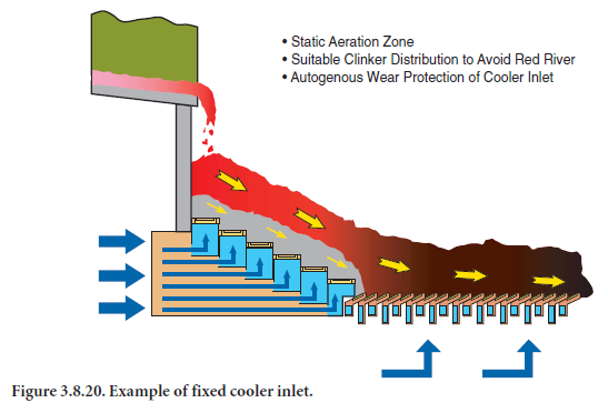
A recent innovation in clinker coolers is the installation of a static grate section at the hot end of the clinker cooler. This has resulted in improved heat recovery and reduced maintenance of the cooler. Modification of the cooler would result in improved heat recovery rates of 2%-5% over a conventional grate cooler.
Clinker Production – Wet Process Kilns
Wet process conversion to semi-dry process (slurry drier). In modernized wet kilns, a slurry drier can be added to dry the slurry before entering the kiln using waste heat from the kiln (Cembureau, 1997). This reduces energy consumption considerably and increases productivity. This is different from a semi-wet process as a gas drier is used instead of a slurry press filter. The drier can be combined with a hammer mill for a reliable and efficient disagglomeration and drying system (Grydgaard, 1998). Gas suspension driers are also considered, but no installation has been built yet (Grydgaard, 1998). Gas suspension driers could increase drying efficiency and potentially reduce fuel consumption in the kiln by up to 1.6 gigajoule/metric ton clinker (Grydgaard, 1998). The principal of preheating/drying is similar to the semi-dry process (or Lepol kiln), although in the semi-dry process dry raw meal (10%-12% water) is used instead of slurry (28%-48% water). The Lepol kiln uses a traveling grate preheater, and uses dry raw material grinding, followed by a pelletizer that mixes water with the dry meal to form pellets that can be carried by the traveling grate into the rotary kiln. The size of the pellets also determines the size of clinker pellets.
The first plant that coupled a drier directly to the kiln was put in operation in 1982 in Sutham, England (Grydgaard, 1998). The first plant in the U.S. to apply the semi-dry process is Lonestar’s Greencastle, Indiana, plant, almost doubling its production capacity to 1.7 million metric tons per year (Anonymous, 2001). No recent estimates of the costs of adding a slurry drier (including waste heat distribution) to an existing wet process kiln were available for this study.
Wet process conversion to semi-wet process (filter press system). In the wet process the slurry typically contains 36% water (range of 24%-48%). A filter press can be installed in a wet process kiln in order to reduce the moisture content to about 20% of the slurry and obtain a paste ready for extrusion into pellets (COWIconsult and others, 1993; Venkateswaran and Lowitt, 1988). In the U.S. several plants have tried slurry filters, but have not been very successful. Currently, there seem to be no plants in the U.S. using this technology (Young, 2002).
Wet process conversion to preheater/precalciner kiln. If economically feasible a wet process kiln can be converted to a state-of-the art dry process production facility that includes either a multi-stage preheater, or a preheater/precalciner. Average specific fuel consumption in U.S. wet kilns is estimated at 6.0 gigajoule/metric ton clinker. Studies of several kiln conversions in the U.S. in the 1980s found fuel savings of 3.4 gigajoule/metric ton or less (Venkateswaran and Lowitt, 1988). In Hranice (Czech Republic) a 1,050 metric ton per day wet process plant was converted to a dry kiln plant with a new kiln specific fuel consumption of 3.13 gigajoule /metric ton clinker (Anonymous, 1994b).
Clinker Production – Dry Process Preheater Kilns
Low pressure drop cyclones for suspension preheaters. Cyclones are a basic component of plants with pre-heating systems. The installation of newer cyclones in a plant with lower pres-sure losses will reduce the power consumption of the kiln exhaust gas fan system. Depending on the efficiency of the fan, 0.6-0.8 kilowatt-hour/metric ton clinker can be saved for each 50 mm W.C. (water column) the pressure loss is reduced. For most older kilns this amounts to savings of 0.6-1.1 kilowatt-hour/metric ton (Birch, 1990). Fujimoto (1994) discussed a Lehigh Cement plant retrofit in which low-pressure drop cyclones were installed in their Mason City, Iowa plant and saved 4.4 kilowatt-hour/metric ton clinker (Fujimoto, 1994). Installation of the cyclones can be expensive, however, since it may often entail the rebuilding or the modification of the preheater tower, and the costs are very site specific. Also, new cyclone systems may increase overall dust load-ing and increase dust carryover from the preheater tower. However, if an inline raw mill follows it, the dust carryover problem becomes less of an issue.
Heat recovery for cogeneration. Waste gas discharged from the kiln exit gases, the clinker cooler system, and the kiln pre-heater system all contain useful energy that can be converted into power. Only in long-dry kilns is the temperature of the exhaust gas sufficiently high, to cost-effec-tively recover the heat through power generation. Cogeneration systems can either be direct gas turbines that utilize the waste heat (top cycle), or the installation of a waste heat boiler system that runs a steam turbine system (bottom cycle). This section focuses on the steam turbine system since these systems have been installed in many plants worldwide and have proven to be economic (Steinbliss, 1990; Jaccard and Willis, 1996; Neto, 1990). Heat recovery has limited application for plants with in-line raw mills, as the heat in the kiln exhaust is used for raw material drying. While electrical efficiencies are still relatively low (18%), based on several case studies power generation may vary between 11-25 kilowatt-hour/metric ton clinker (Scheur & Sprung, 1990; Steinbliss, 1990; Neto,1990). Electricity savings of 20 kWh/metric ton clinker are assumed. In 1999, 4 U.S. cement plants cogenerated 486 million kWh (USGS, 2001). Assuming that 34% of the energy introduced into long dry kilns is exhausted as waste gas (Venkateswaran and Lowitt, 1988), this suggests a potential generation of 1200 GWh.
Dry process conversion to multi-stage preheater kiln. Older dry kilns may only preheat in the chain section of the long kiln, or may have single- or two-stage preheater vessels. Especially, long dry kilns may not have any preheater vessels installed at all. This leads to a low efficiency in heat transfer and higher energy consumption. Installing multi-stage suspension preheating (i.e., four- or five-stage) may reduce the heat losses and thus increase efficiency. Modern cyclone or suspension preheaters also have a reduced pressure drop, leading to increased heat recovery effi-ciency and reduced power use in fans (see low pressure drop cyclones above). By installing new preheaters, the productivity of the kiln will increase, due to a higher degree of pre-calcination (up to 30%-40%) as the feed enters the kiln. Also, the kiln length may be shortened by 20%-30%thereby reducing radiation losses (van Oss, 1999). As the capacity increases, the clinker cooler may have to be adapted to be able to cool the large amounts of clinker. The conversion of older kilns is attractive when the old kiln needs replacement and a new kiln would be too expensive, assuming that limestone reserves are adequate.
Energy savings depend strongly on the specific energy consumption of the dry process kiln to be converted as well as the number of preheaters to be installed. For example, cement kilns in the former German Democratic Republic were rebuilt by Lafarge to replace four dry process kilns originally constructed in 1973 and 1974. In 1993 and 1995 three kilns were equipped with four-stage suspension preheaters.
The specific fuel consumption was reduced from 3.9 gigajoule/metric ton to 3.4 gigajoule/metric ton clinker, while the capacity of the individual kilns was increased from 1500 to 2300 metric tons per day (Duplouy and Trautwein, 1997). In the same project, the power consumption was reduced by 25%, due to the replacement of fans and the finish grinding mill. Energy savings are estimated at 0.9 gigajoule/metric ton clinker for the conversion which reflects the difference between the average dry kiln specific fuel consumption and that of a modern preheater kiln, based on a study of the Canadian cement industry (Holderbank, 1993).
Installation or upgrading of a preheater to a preheater/precalciner kiln. An existing preheater kiln may be converted to a multi-stage preheater precalciner kiln by adding a precalciner and, when possible an extra preheater. The addition of a precalciner will generally increase the capacity of the plant, while lowering the specific fuel consumption and reducing thermal NOX emissions (due to lower combustion temperatures in the precalciner) compared to the rotary kiln burning zone. Using as many features of the existing plant and infrastructure as possible, special precalciners have been developed by various manufacturers to convert existing plants, e.g., Pyroclon®-RP by KHD in Germany. Generally, the kiln, foundation and towers are used in the new plant, while cooler and preheaters are replaced. Cooler replacement may be necessary in order to increase the cooling capacity for larger production volumes. The conversion of a plant in Italy, using the existing rotary kiln, led to a capacity increase of 80%-100% (from 1000 metric tons per day to 1800-2000 metric tons per day), while reducing specific fuel consumption from 3.56 to 3.06-3.19 gigajoule/metric ton clinker, resulting in savings of 11%-14% (Sauli, 1993). Fuel savings will depend strongly on the efficiency of the existing kiln and on the new process parameters (e.g., degree of precalcination, cooler efficiency).
Older calciners can also be retrofitted for energy efficiency improvement and NOX emission reduc-tion. Retrofitting the pre-calciner at the Lengerich plant of Dyckerhoff Zement (Germany) in 1998 reduced NOX emissions by almost 45% (Mathée, 1999). Similar emission reductions have been found at kilns in Germany, Italy and Switzerland (Menzel, 1997). Ash Grove’s Durkee, Oregon orig-inal 1979 plant installed new preheaters and a precalciner in 1998, expanding production from 1500 metric tons per day to 2500 metric tons per day (Hrizuk, 1999). The reconstruction reduced fuel consumption by 0.16-0.7 gigajoule/metric ton clinker (Hrizuk, 1999), while reducing NOX emissions. Capitol Cement (San Antonio, Texas) replaced an older in-line calciner with a new downdraft calciner to improve production capacity. This was part of a larger project replacing preheaters, installing SO2 emission reduction equipment, as well as increasing capacity of a roller mill. The new plant was successfully commissioned in 1999. Fuel consumption at Capitol Cement was reduced to 3.4 gigajoule/metric ton of clinker (Frailey & Happ, 2001).
Conversion of long dry kilns to preheater/precalciner kiln. If economically feasible a long dry kiln can be upgraded to the current state of the art multi-stage preheater/precalciner kiln. Energy savings are estimated at 1.3 gigajoule/metric ton clinker for the conversion. These savings reflect the difference between the average dry kiln specific fuel consumption and that of a modern preheater, pre-calciner kiln based on a study of the Canadian cement industry and the retrofit of an Italian plant (Holderbank, 1993; Sauli, 1993).
Finish Grinding
Process control and management grinding mills. Control systems for grinding opera-tions are developed using the same approaches as for kilns (see above). The systems control the flow in the mill and classifiers, attaining a stable and high quality product. Several systems are marketed by a number of manufacturers. Expert systems have been commercially available since the early 1990s. The Karlstadt plant of Schwenk KG (Germany) implemented an expert system in a finishing mill in 1992, increasing mill throughput and saving energy. Magotteaux (Belgium) has marketed a control system for mills since 1998 and has sold six units to plants in Germany (Rohrdorfer Zement), Greece (Heracles General Cement), SouthAfrica (PPC Group) and the United Kingdom (UK) (Rugby Group). Experience with a cement mill at the South Ferriby plant of the Rugby Group in the UK showed increased production (+3.3%) and power savings equal to 3%, while the standard deviation in fineness went down as well (Van den Broeck, 1999). Krupp Polysius markets the PolExpert system and reports energy savings between 2.5% and 10% (typi-cally 8%), with increased product quality (lower deviation) and production increases of 2.5% 10%, after installing control systems in finishing mills (Goebel, 2001). Similar results have been achieved with model predictive control (using neural networks) for a cement ball mill at a South-African cement plant (Martin and McGarel, 2001). Pavilion Technologies (US) has developed a new control system using neural networks. Pavilion Technologies reports a 4%-6% throughput increase (and corresponding reduction in specific power consumption) for installing a model predictive control system in finish ball mill (Martin and others, 2001). Penetration of advanced control systems for cement mills in the U.S. is still relatively low. For example, Krupp Polysius has not sold any PolExpert systems in the U.S. despite worldwide sales (Goebel, 2001).
Advanced grinding concepts. The energy efficiency of ball mills for use in finish grinding is relatively low (Marchal, 1997; Cembureau, 1997). Several new mill concepts exist that can signifi-cantly reduce power consumption in the finish mill to 22-33 kilowatt-hour/metric ton clinker, including roller presses, roller mills, and roller presses used for pre-grinding in combination with ball mills (Alsop and Post, 1995; Cembureau, 1997; Seebach and others, 1996). Roller mills employ a mix of compression and shearing, using 2-4 grinding rollers carried on hinged arms riding on a horizontal grinding table (Cembureau, 1997; Alsop and Post, 1995).
Air swept vertical roller mills with integral classifiers are used for finish grinding, whereas a recent off-shoot technology which is not air swept is now being used as a pre-grinding system in combi-nation with a ball mill. A new mill concept is the Horomill, first demonstrated in Italy in 1993 (Buzzi, 1997). In the Horomill a horizontal roller within a cylinder is driven. The centrifugal forces resulting from the movement of the cylinder cause a uniformly distributed layer to be carried on the inside of the cylinder. The finished product is collected in a dust filter. The Horomill is a com-pact mill that can produce a finished product in one step and hence has relatively low capital costs.
Today, high-pressure roller presses are most often used to expand the capacity of existing grinding mills, and are found especially in countries with high electricity costs or with poor power supply (Seebach and others, 1996). After the first demonstration of the Horomill in Italy, this concept is now also applied in plants in Mexico (Buzzi, 1997), Germany, Czech Republic and Turkey (Duplouy and Trautwein, 1997). New designs of the roller mills allow for longer operation times (> 20,000 hours). The electricity savings of a new finish grinding mill when replacing a ball mill is estimated at 30 kilowatt-hour/metric ton cement.
High efficiency classifiers. A recent development in efficient grinding technologies is the use of high-efficiency classifiers or separators. Classifiers separate the finely ground particles from the coarse particles. The large particles are then recycled back to the mill. Standard classifiers may have a low separation efficiency, which leads to the recycling of fine particles, resulting in extra power use in the grinding mill. In high-efficiency classifiers, the material is more cleanly separated, thus reducing over-grinding. High efficiency classifiers or separators have had the greatest impact on improved product quality and reducing electricity consumption.
Improved grinding media. Improved wear resistant materials can be installed for grinding media, especially in ball mills. Grinding media are usually selected according to the wear character-istics of the material. Increases in the ball charge distribution and surface hardness of grinding media and wear resistant mill linings have shown a potential for reducing wear as well as energy consumption. (Venkateswaran and Lowitt, 1988). Improved balls and liners made of high chromium steel is one such material but other materials are also possible. Other improvements include the use of improved liner designs, such as grooved classifying liners. These have the poten-tial to reduce grinding energy use by 5%-10% in some mills (Venkateswaran and Lowitt, 1988).
Plant-Wide Measures
Preventative maintenance. Preventative maintenance includes training personnel to be atten-tive to energy consumption and efficiency. Successful programs have been launched in a variety of industries (Caffal, 1995; Nelson, 1994). While many processes in cement production are primarily automated, there still are opportunities, requiring minimal training of employees, to increase energy savings. Also, preventative maintenance (e.g., for the kiln refractory) can increase a plant’s utilization ratio, since it has less downtime over the long term. Birch (1990) mentions that the reduction of false air input into the kiln at the kiln hood has the potential to save 11 kcal/kg clinker. This is used as the estimate of fuel savings. Lang (1994) notes a reduction of up to 5 kWh for various preventative maintenance and process control measures. Based on similar programs in other industries, annual and start up costs for implementing this training are estimated to be mini-mal and would be paid back in less than one year. For preventative maintenance of compressed air systems see below.
High-efficiency motors and drives. Motors and drives are used throughout the cement plant to drive fans (preheater, cooler, alkali bypass), rotate the kiln, transport materials and, most impor-tantly, for grinding. In a typical cement plant, 500-700 electric motors may be used, varying from a few kW to MW-size (Vleuten, 1994). Power use in the kiln (excluding grinding) is roughly esti-mated at 40-50 kilowatt-hour/metric ton clinker (Heijningen and others, 1992). Variable speed drives, improved control strategies and high-efficiency motors can help to reduce power use in cement kilns. If the replacement does not influence the process operation, motors may be replaced at any time. However, motors are often rewired rather than being replaced by new motors. Power savings may vary considerably on a plant-by-plant basis, ranging from 3% to 8% (Fujimoto, 1994). Vleuten (1994) estimates the potential power savings at 8% of the power use.
Adjustable or variable speed drives. Drives are the largest power consumers in cement making. The energy efficiency of a drive system can be improved by reducing the energy losses or by increasing the efficiency of the motor (see above). Decreasing throttling can reduce energy losses in the system and coupling losses through the installation of adjustable speed drives (ASD). Most motors are fixed speed AC models. However, motor systems are often operated at partial or variable load (Nadel and others, 1992). Also, in cement plants large variations in load occur (Bösche, 1993). There are various technologies to control the motor (Worrell and others, 1997). The systems are offered by many suppliers and are available worldwide. Worrell and others (1997) provide an overview of savings achieved with ASD in a wide array of applications. The savings depend on the flow pattern and loads. The savings may vary between 7% and 60%. ASD equip-ment is used more and more in cement plants (Bösche, 1993; Fujimoto, 1993), but the application may vary widely, depending on electricity costs. Within a plant, ASDs can mainly be applied for fans in the kiln, cooler, preheater, separator and mills, and for various drives. For example, St. Marys Cement Bowmanville plant (Canada) installed a variable air inlet fan, reducing electricity and fuel use in the kiln (because of reduced inlet air volume) (CIPEC, 2001). One case study for a modern cement plant estimated potential application for 44% of the installed motor power capac-ity in the plant (Bösche, 1993). ASDs for clinker cooler fans have a low payback, even when energy savings are the only reason for installing ASDs (Holderbank, 1993). Energy savings strongly depend on the application and flow pattern of the system on which the ASD is installed. Although savings are significant (Holderbank, 1993), not many quantitative studies are available for the cement industry. One hypothetical case study estimates the savings at 70%, compared to a system with a throttle valve (or 37% compared with a regulated system) for the raw mill fan (Bösche, 1993). In practice savings of 70% are unrealistic (Young, 2002). Fujimoto, (1994) notes that Lafarge Canada’s Woodstock plant replaced their kiln ID fans with ASDs and reduced electricity use by 5 kilowatt-hour/metric ton. It is estimated the potential savings are at 15% for 44% of the installed power. The specific costs depend strongly on the size of the system.
Compressed air systems. Compressed air systems are used in different parts of the plants, i.e., mixing of slurry (in wet process plants) and in the baghouse Pulse-Jet or Plenum Pulse dust collec-tor filters and other parts. Total energy consumption by compressed air systems is relatively small in cement plants, however, it can amount to a considerable expense if the systems run continu-ously and end-uses are offline. Still, energy efficiency improvement measures may be found in these systems. Compressed air is probably the most expensive form of energy available in a plant because of its poor efficiency. Typically overall efficiency is around 10% for compressed air (LBNL and RDC, 1998). Because of this inefficiency, if compressed air is used, it should be of minimum quantity for the shortest possible time, constantly monitored and weighed against alternatives.
Maintenance of compressed air systems. Inadequate maintenance can lower compression efficiency and increase air leakage or pressure variability, as well as lead to increased operating temperatures, poor moisture control, and excessive contamination. Improved maintenance will reduce these problems and save energy. Proper maintenance includes the following (LBNL and RDC, 1998):
•Keep the compressor and intercooling surfaces clean and foul-free. Blocked filters increase pres-sure drop. By inspecting and periodically cleaning filters, the pressure drop may be kept low. Fixing improperly operating filters will also prevent contaminants from entering into tools and causing them to wear out prematurely. Also, consider adding filters in parallel that decrease air velocity, and, therefore, decrease air pressure drop. A 2% reduction of annual energy consumption in compressed air systems is projected for more frequent filter changing (Radgen and Blaustein, 2001).
• Keep motors properly lubricated and cleaned. Poor motor cooling can increase motor tempera-ture and winding resistance, shortening motor life, in addition to increasing energy consump-tion. Compressor lubricant should be changed every 2 to 18 months and checked to make sure it is at the proper level. In addition to energy savings, this can help avoid corrosion and degra-dation of the system.
• Inspect drain traps periodically to ensure they are not stuck in either the open or closed posi-tion and are clean. Some users leave automatic condensate traps partially open at all times to allow for constant draining. This practice wastes substantial energy and should never be undertaken. Instead, install simple pressure driven valves. Malfunctioning traps should be cleaned and repaired instead of left open. Some auto drains, such as float switch or electronic drains, do not waste air.
• Maintain the coolers on the compressor to ensure that the dryer gets the lowest possible inlet temperature (Ingersoll-Rand, 2001).
• Check belts for wear and adjust them. A good rule of thumb is to adjust them every 400 hours of operation.
• Replace air lubricant separators according to specifications or sooner. Rotary screw compres-sors generally start with their air lubricant separators having a 2 to 3 psid pressure drop at full load. When this increases to 10 psid, change the separator (LBNL and RDC, 1998).
• Check water cooling systems for water quality (pH and total dissolved solids), flow, and temper-ature. Clean and replace filters and heat exchangers per manufacturer’s specificationsm.
Reduce leaks. Leaks can be a significant source of wasted energy. A typical plant that has not been well maintained will likely have a leak rate equal to 20% to 50% of total compressed air production capacity (Ingersoll Rand, 2001; Price and Ross, 1989). Leak maintenance can reduce this number to less than 10%. Overall, a 20% reduction of annual energy consumption in compressed air systems is projected for fixing leaks (Radgen and Blaustein, 2001). Estimations of leaks vary with the size of the hole in the pipes or equipment. In addition to increased energy consumption, leaks can make air tools less efficient and adversely affect production, shorten the life of equipment, lead to additional maintenance requirements and increase unscheduled down-time. In the worst case, leaks can add unnecessary compressor capacity.
The most common areas for leaks are couplings, hoses, tubes, fittings, pressure regulators, open condensate traps and shut-off valves, pipe joints, disconnects, and thread sealants. A simple way to detect leaks is to apply soapy water to suspect areas. The best way to detect leaks is to use an ultra-sonic acoustic detector, which can recognize the high frequency hissing sounds associated with air leaks. After identification, leaks should be tracked, repaired, and verified. Leak detection and correction programs should be ongoing efforts.
Reducing the inlet air temperature. Reducing the inlet air temperature reduces energy used by the compressor. In many plants, it is possible to reduce inlet air temperature to the compressor by taking suction from outside the building. As a rule of thumb, each 3°C will save 1% compressor energy use (CADDET, 1997b; Parekh, 2000).
Maximize allowable pressure dew point at air intake. Choose the dryer that has the maximum allowable pressure dew point, and best efficiency. A rule of thumb is that desiccant dryers consume %7 to 14% of the total energy of the compressor, whereas refrigerated dryers consume 1% to 2% as much energy as the compressor (Ingersoll Rand, 2001). Consider using a dryer with a floating dew point.
Compressor controls. The objective of any control strategy is to shut off unneeded compressors or delay bringing on additional compressors until needed. All units that are on should be running at full-load, except for one. Positioning of the control loop is also important; reducing and controlling the system pressure downstream of the primary receiver can result in energy consumption of up to 10% or more (LBNL, and others, 1998). Energy savings for sophisticated controls are 12% annually (Radgen and Blaustein, 2001). Start/stop, load/unload, throttling, multi-step, variable speed and network controls are options for compressor controls and described below.
Start/stop (on/off) is the simplest control available and can be applied to reciprocating or rotary screw compressors. For start/stop controls, the motor driving the compressor is turned on or off in response to the discharge pressure of the machine. They are used for applications with very low duty cycles. Applications with frequent cycling will cause the motor to overheat.
Load/unload control, or constant speed control, allows the motor to run continuously but unloads the compressor when the discharge pressure is adequate. In most cases, unloaded rotary screw compressors still consume 15% to 35% of full-load power while delivering no useful work (LBNL and RDC, 1998). Hence, load/unload controls can be inefficient.
Modulating or throttling controls allow the output of a compressor to be varied to meet flow requirements by closing down the inlet valve and restricting inlet air to the compressor. Throttling controls are applied to centrifugal and rotary screw compressors. Changing the compressor control from on/zero/off to a variable speed control can save up to 8% per year (CADDET, 1997b).
Sizing pipe diameter correctly. Inadequate pipe sizing can cause pressure losses, increase leaks and increase generating costs. Pipes must be sized correctly for optimal performance or resized to fit the current compressor system. Increasing pipe diameter typically reduces annual energy consumption by 3% (Radgen and Blaustein, 2001).
Heat recovery for water preheating. As much as 80% to 93% of the electrical energy used by an industrial air compressor is converted into heat. In many cases, a heat recovery unit can recover 50% to 90% of this available thermal energy for space heating, industrial process heating, water heating, makeup air heating, boiler makeup water preheating, industrial drying, industrial cleaning processes, heat pumps, laundries or preheating aspirated air for oil burners (Parekh, 2000). Heat recovery for space heating is not as common with water-cooled compressors because an extra stage of heat exchange is required and the temperature of the available heat is lower. However, with large water cooled compressors, recovery efficiencies of 50% to 60% are typical (LBNL and RDC, 1998). Implementing this measure saves up to 20% of the energy used in compressed air systems annually for space heating (Radgen and Blaustein, 2001).
Lighting
Energy use for lighting in the cement industry is very small. Still, energy efficiency opportunities may be found that can reduce energy use cost-effectively. Lighting is used either to provide overall ambient lighting throughout the manufacturing, storage and office spaces or to provide low-bay and task lighting to specific areas. High-intensity discharge (HID) sources are used for the former, including metal halide, high-pressure sodium and mercury vapor lamps. Fluorescent, compact fluorescent (CFL) and incandescent lights are typically used for task lighting in offices.
Lighting controls. Lights can be shut off during non-working hours by automatic controls, such as occupancy sensors which turn off lights when a space becomes unoccupied. Manual controls can also be used in addition to automatic controls to save additional energy in smaller areas.
Replace T-12 tubes by T-8 tubes. In industry, typically T-12 tubes have been used. T-12 refers to the diameter in 1/8 inch increments (T-12 means 12/8 inch or 3.8 cm diameter tubes). The initial output for these lights is high, but energy consumption is also high. They also have extremely poor efficacy, lamp life, lumen depreciation, and color rendering index. Because of this, maintenance and energy costs are high. Replacing T-12 lamps with T-8 lamps (smaller diameter) approximately doubles the efficacy of the former.
Replace mercury lights by metal halide or high pressure sodium lights. Where color rendition is critical, metal halide lamps can replace mercury or fluorescent lamps with an energy savings of 50%. Where color rendition is not critical, high pressure sodium lamps offer energy savings of 50% to 60% compared to mercury lamps (Price and Ross, 1989).
Replace metal halide HID with high-intensity fluorescent lights. Traditional HID light-ing can be replaced with high-intensity fluorescent lighting. These new systems incorporate high-efficiency fluorescent lamps, electronic ballasts and high-efficacy fixtures that maximize output to the work plane. Advantages to the new system are many; they have lower energy consumption, lower lumen depreciation over the lifetime of the lamp, better dimming options, faster start-up and restrike capability, better color rendition, higher pupil lumens ratings and less glare. (Martin and others, 2000). High-intensity fluorescent systems yield 50% electricity savings over standard metal halide HID. Dimming controls that are impractical in the metal halide HIDs can also save significant energy. Retrofitted systems cost about $185 per fixture, including installation costs (Martin and others, 2000). In addition to energy savings and better lighting qualities, high-inten-sity fluorescents can help improve productivity and have reduced maintenance costs.
Replace magnetic ballasts with electronic ballasts. A ballast is a mechanism that regulates the amount of electricity required to start a lighting fixture and maintain a steady output of light. Electronic ballasts save 12-25 percent more power than their magnetic predecessors do (USEPA, 2001).
Product and Feedstock Changes
Alkali content. In North America, part of the production of the cement industry are cements with a low alkali content (probably around 20%-50% of the market), a much higher share than found in many other countries (Holderbank, 1993). In some areas in the U.S., aggregate quality may be such that low-alkali cements are required by the cement company’s customers. Reducing the alkali content is achieved by venting (called the by-pass) hot gases and particulates from the plant, loaded with alkali metals. The by-pass also avoids plugging in the preheaters. This becomes cement kiln dust (CKD). Disposal of CKD is regulated under the Resource Conservation and Recovery Act (RCRA).
Many customers demand a lower alkali content, as it allows greater freedom in the choice of aggregates. The use of fly-ash or blast-furnace slags as aggregates (or in the production of blended cement, see below) may reduce the need for low-alkali cement. Low alkali cement production leads to higher energy consumption. Savings of 2-5 Kcal/kg per percent bypass are assumed (Alsop and Post, 1995). The lower figure is for precalciner kilns, while the higher figure is for preheater kilns. Typically, the bypass takes 10%-70% of the kiln exhaust gases (Alsop and Post, 1995). Additionally, electricity is saved due to the increased cement production, as the CKD would otherwise end up as clinker. There are no investments involved in this product change, although cement users (e.g., ready-mix producers) may need to change the type of aggregates used (which may result in costs). Hence, this measure is most successfully implemented in coordination with ready-mix producers and other large cement users.
Blended cements. The production of blended cements involves the intergrinding of clinker with one or more additives (fly ash, pozzolans, granulated blast furnace slag, silica fume, and volcanic ash) in various proportions. The use of blended cements is a particularly attractive effi-ciency option since the intergrinding of clinker with other additives not only allows for a reduction in the energy used (and carbon emissions) in clinker production, but also corresponds to a reduc-tion in carbon dioxide emissions in calcination as well. Blended cement has been used for many decades and longer around the world.
Blended cements are very common in Europe, and blast furnace and pozzolanic cements account for about 12% of total cement production with portland composite cement accounting for an additional 44% (Cembureau, 1997). Blended cement was introduced in the U.S. to reduce produc-tion costs for cement (especially energy costs), expand capacity without extensive capital costs, to reduce emissions from the kiln. In Europe a common standard has been developed for 25 types of cement (using different compositions for different applications). The European standard allows wider applications of additives. Many other countries around the world use blended cement. Blended cements demonstrate a higher long-term strength, as well as improved resistance to acids and sulfates, while using waste materials for high-value applications. Short-term strength (meas-ured after less than 7 days) may be lower, although cement containing less than 30% additives will generally have setting times comparable to concrete based on portland cement.
In the U.S. the consumption and production of blended cement is still limited. In the U.S., the most prevalent blending materials are fly ash and granulated blast furnace slag. Not all slag and fly ash is suitable for cement production. It is estimated that 68% of the fly ash in the U.S. conforms to ASTM C 618 (PCA, 1997). Currently, only a small part of the blast furnace slag is produced as granulated slag, while the majority is air-cooled. Air-cooled slag cannot be used for cement production, and is of lesser value. However, investments in slag processing by slag processors and cement companies will increase this fraction. ASTM Standards exist for different types of blended cements, i.e., C 989 (slag cement), C 595 and C 1157. USEPA (2000) has issued procurement guide-lines to support the use of blended cement in (federal) construction projects.
A recent analysis of the U.S. situation cited an existing potential of producing 31 million metric tons of blended cement in 2000 using both fly ash and blast furnace slag, or 36% of U.S. capacity (PCA, 1997). This analysis was based on estimates of the availability of intergrinding materials and surveying ready-mix companies to estimate feasible market penetration.
The blended cement produced would have, on average, a clinker/cement ratio of 65% or would result in a reduction in clinker production of 9.3 million metric tons. The reduction in clinker production corresponds to a specific fuel savings of 1.42 gigajoule/metric ton. There is an increase in fuel use of 0.09 gigajoule/metric ton for drying of the blast furnace slags but a corresponding energy savings of 0.2 gigajoule/metric ton for reducing the need to use energy to bypass kiln exit gases to remove alkali-rich dust. The bypass savings are due to the fact that blended cements offer an additional advantage in that the interground materials also lower alkali-silica reactivity (ASR) thereby allowing a reduction in energy consumption needed to remove the high alkali content kiln dusts. In practice, bypass savings may be minimal to avoid plugging of the preheaters, requiring a minimum amount of bypass volume. This measure therefore results in total fuel savings of 1.41 gigajoule/metric ton blended cement. Electricity consumption however is expected to increase due to the added electricity consumption associated with grinding blast furnace slag (as other materials are more or less fine enough).
The costs of applying additives in cement production may vary. Capital costs are limited to extra storage capacity for the additives. However, blast furnace slag may need to be dried before use in cement production. This can be done in the grinding mill, using exhaust from the kiln, or supple-mental firing, either from a gas turbine used to generate power or a supplemental air heater. The operational cost savings will depend on the purchase (including transport) costs of the additives1, the increased electricity costs for (finer) grinding, the reduced fuel costs for clinker production and electricity costs for raw material grinding and kiln drives, as well as the reduced handling and mining costs. These costs will vary by location, and would need to be assessed on the basis of indi-vidual plants.
Limestone portland cement. Similar to blended cement, ground limestone is interground with clinker to produce cement, reducing the needs for clinker-making and calcination. This reduces energy use in the kiln and clinker grinding and CO2 emissions from calcination and energy use. Addition of up to 5% limestone has shown to have no negative impacts on the per-formance of portland cement, while an optimized limestone cement would improve the workabil-ity slightly (Detwiler and Tennis, 1996). Adding 5% limestone would reduce fuel consumption by 5%, power consumption for grinding, and CO2 emissions by almost 5%. Additional costs would be minimal, limited to material storage and distribution, while reducing kiln operation costs by 5%.
CemStar®. Texas Industries (Midlothian, Texas) in 1994 developed a system to use electric arc furnace (EAF) slags of the steel industry as input in the kiln, reducing the use of limestone. The slag contains C2S, which can be converted to C3S with far less energy than can limestone. The slags replace limestone (approximately 1.6 times the weight in limestone). EAFs produce between 55-210 kilograms of slag per metric ton of steel (OIT, 1996). EAF steel production is estimated at almost 45.1 million metric ton. EAF-slag production is estimated at 5.3 million metric tons, potentially replacing an equal amount of clinker. The CemStar® process allows replacing 10%-15% of the clinker by EAF-slags, reducing energy needs for calcination. The advantage of the CemStar‚ process is the lack of grinding the slags, but adding them to the kiln in 5 centimeter lumps. Depending on the location of injection it may also save heating energy. Calcination energy is estimated at 1.9 gigajoule/metric ton clinker (Worrell and others, 2001). Because the lime in the slag is already calcined, it also reduces CO2 emissions from calcination, while the reduced combustion energy and lower flame temperatures lead to reduced NOX emissions (Battye and others, 2000). For illus-trative purposes alone, using a 10% injection of slags would reduce energy consumption by 0.19 gigajoule/metric ton of clinker, while reducing CO2 emissions by roughly 11%. Energy savings can be higher in wet kilns due to the reduced evaporation needs.
Reductions in NOX emissions vary by kiln type and may be between 9% and 60%, based on measurements at two kilns (Battye and others, 2000). Costs savings consist of increased income from additional clinker produced without increased operation and energy costs, as well as reduced iron ore purchases (as the slag provides part of the iron needs in the clinker). The iron content needs to be balanced with other iron sources such as tires and iron ore. USEPA awarded the CemStar® process special recognition in 1999 as part of the ClimateWise program.
Reducing the fineness for particular applications. Cement is normally ground to a uniform fineness. However, the applications of cement vary widely, and so does the optimal fine-ness. The grinding of the cement to the desired fineness could reduce the energy demand for grinding. Holderbank (1993) suggests that cement in Canada and the U.S. is ground finer (on aver-age) than in Western Europe, which suggests that energy savings could be achieved. The exact savings will depend on the grindability of the clinker. As a rule of thumb, for each 100 additional Blaine points, grinding power requirements increase by 5% (Holderbank, 1993). Holderbank(1993) reviewed 23 European and 20 North-American plants and found that the European plants use on average less energy per unit of cement for grinding than the North-American plants. Note that finer cement may reduce the amount of concrete needed for a structure, due to the higher strength. It is hard to estimate the total savings due to the many factors affecting strength of concrete and grinding energy requirements. Also, without a detailed assessment of the market and applications of cement, it is difficult to estimate the total potential contribution of this measure to potential energy savings in the U.S. cement industry.
Advanced Technologies
In this section several advanced technologies for cement production are discussed. As our study focuses on commercially available technologies, the advanced technologies are not included in the analysis of the cost-effective potential for energy efficiency improvement. They are discussed for completeness of the technical analysis.
Fluidized bed kiln. The Fluidized Bed Kiln (FBK) is a totally new concept to produce clinker. Developments in FBK technology started as early as the 1950s (Venkateswaran and Lowitt, 1988). Today, developments mainly take place in Japan (Kawasaki Heavy Industries) and the U.S. (Fuller Co.) (Cohen, 1995; Van Kuijk and others,1997). In an FBK, the rotary kiln is replaced by a station-ary vertical cylindrical vessel, in which the raw materials are calcined in a fluidized bed. An over-flow at the top of the reactor regulates the transfer of clinker to the cooling zone. The (expected) advantages of FBK technology are lower capital costs because of smaller equipment, lower temper-atures resulting in lower NOX-emissions and a wider variety of the fuels that can be used, as well as lower energy use. The Kawasaki design uses cyclone preheaters, a precalciner kiln and a fluidized bed kiln. Energy use is expected to be 10%-15% lower compared to conventional rotary kilns (Vleuten, 1994). The Fuller Co. stood at the basis of the U.S. development of a fluidized bed kiln for clinker making. Early developments did not prove to be commercially successful due to the high clinker recycling rate (Cohen, 1992) and were commercialized for alkali dust recycling only (Cohen, 1993). The technology was also used in the development of the advanced cement furnace (CAF). CAF uses a preheated pellet feed, using primarily natural gas or liquid fuels (Cohen, 1993).
A pilot plant was built and used to produce clinker. The NOX emissions were reduced to 0.86 kilo-grams/metric ton clinker, compared to 2.3-2.9 kilograms/metric ton for conventional plants due to lower combustion temperatures (Cohen, 1993). The future fuel consumption is estimated at 2.93-3.35 gigajoule/metric ton clinker (Cohen, 1995). The fuel use of the FBK may be lower than that of conventional rotary kilns, although modern precalciner rotary kilns have shown fuel use of 2.9-3.0 gigajoule/metric ton clinker. No data are available on the expected power use for the FBK. The use of the FBK may result in lower alkali-content of the clinker (Cohen, 1992). FBK needs less space and also has a higher flexibility with respect to raw material feed.
Advanced comminution technologies. Grinding is an important power consumer in modern cement-making. However, current grinding technologies are highly inefficient. Over 95% of the energy input in the grinding process is lost as waste heat, while only 1%-5% of the energy input is used to create new surface area (Venkateswaran and Lowitt, 1988). Some of the heat may be used to dry the raw materials, for example in finish grinding or the grinding of limestone. Current high-pressure processes already improve the grinding efficiency in comparison with conventional ball mills (see above). In the longer term, further efficiency improvements can be expected when non-mechanical “milling” technologies become available (OTA, 1993). Non-mechanical systems may be based on ultrasound (Suzuki and others, 1993), laser, thermal shock, electric shock or cryogenics. However, non-mechanical grinding technologies have not been demonstrated yet and will not be commercially available in the next decades. Although the theoretical savings of non-mechanical comminution are large, no estimate of the expected savings can be given at this stage of fundamen-tal research.
Mineral polymers. Clinker is made by calcining calcium carbonate (limestone), which releases CO2 into the atmosphere. Mineral polymers can be made from inorganic alumino-silicate compounds. An inorganic polycondensation reaction results in a three-dimensional structure, like that of zeolites. It can be produced by blending three elements, i.e., calcined alumino-silicates (from clay), alkali-disilicates and granulated blast furnace slag or fly-ash (Davidovits, 1994). The cement hardens at room temperatures and provides compressive strengths of 20 MPa after 4 hours and up to 70-100 MPa after 28 days (Davidovits, 1994). The zeolite-like matrix results in the immobilization of materials, e.g., wastes. Despite the high alkali content, mineral polymers do not show alkali aggregate reactions (Davidovits, 1993). Research on mineral polymers was already going on in Eastern Europe and the U.S in the early 1980s. CO2 emissions from the production of mineral polymers are determined by the carbon content of the raw materials and the energy used in the production. The silica-alumina raw materials can be found on all continents. Calcination of the potassium or sodium may result in CO2 emissions. Research in this area is still ongoing. The manufacturing of mineral polymers is done at relatively low temperatures. The calcining of alumino-silicates occurs at temperatures of 750°C (Davidovits, 1994). However, no energy consumption data have been found in the literature.
REFERENCES
Alsop, P. A., and Post, J. W., The Cement Plant Operations Handbook, (First edition), Tradeship Publications Ltd., Dorking, UK, 1995.
Anonymous (1994b), “Cement Plant Modernization in Central Europe,” World Cement,
(November), 1994.
Anonymous, “Greencastle Cement Expands, Uses New production Process” Mining Engineering, 1 53, January 2001.
Battye, R.; Walsh, S.; and Lee-Greco, J., NOX Control Technologies for the Cement Industry, Prepared for United States Environmental Protection Agency, Research Triangle Park, North Carolina, USA, 2000.
Birch, E., “Energy Savings in Cement Kiln Systems,” Energy Efficiency in the Cement Industry, (Ed. J. Sirchis), Elsevier Applied Science, London, England, UK, 1990.
Bösche, A., “Variable Speed Drives in Cement Plants,” World Cement, 6 24, 1993.
Buzzi, S., “Die Horomill® – Eine Neue Mühle für die Feinzerkleinerung,” ZKG International, 3 50, 1997.
Buzzi, S., and Sassone, G. “Optimization of Clinker Cooler Operation,” Proc. VDZ Kongress 1993: “Verfahrenstechnik der Zementherstellung” Bauverlag, Wiesbaden, Germany, 1993.
Caffal, C., “Energy Management in Industry,” CADDET Analyses Series 17, Centre for the Analysis and Dissemination of Demonstrated Energy Technologies, Sittard, the Netherlands, 1995.
Cembureau, Best Available Techniques for the Cement Industry, Cembureau, Brussels, Belgium, 1997.
CKRC, “Volume of Hazardous Wastes Used as Fuel in Cement Kilns,” http://www.ckrc.org/infocen.html, Cement Kiln Recycling Coalition, Washington, DC, USA, 2002.
CADDET, “Tyres Used as Fuel in Cement Factory,” Centre for the Analysis and Dissemination of Demonstrated Energy Technologies, Sittard, the Netherlands, 1996.
CADDET (1997a), Revolutionary Low-NOX HighEefficiency Gas Burner, Centre for the Analysis and Dissemination of Demonstrated Energy Technologies Sittard, the Netherlands, 1997.
CADDET (1997b), Saving Energy with Efficient Compressed Air Systems, Maxi Brochure 06, Centre for the Analysis and Dissemination of Demonstrated Energy Technologies, Sittard, The Netherlands, 1997.
CIPEC, “Blue Circle Cement Fires Up Energy savings at Ontario Plants,” Heads Up CIPEC, 5 21, Office of Energy Efficiency, Natural Resources Canada, Ottawa, Ontario, Canada, 2001.
Cohen, S. M., “Fluid Bed Cement Clinker Applications,” Proc. 1992 IEEE Cement Industry Technical Conference XXXIV, Dallas, TX, May 10-14, 1992, Institute of Electrical and Electronics Engineers Inc. New York, NY, USA, 1992.
Cohen, S. M., “Fluid-Bed Cement Clinker Applications,” Proc. VDZ Kongress 1993:
“Verfahrenstechnik der Zementherstellung, Bauverlag, Wiesbaden, Germany, 1993.
Cohen, S. M., “Anwendungsmöglichkeiten der Wirbelschicht bei der Zementherstellung” Zement-Kalk-Gips, 1 48, 1995.
COWIconsult; March Consulting Group; and MAIN, “Energy Technology in the Cement Industrial Sector,” Report prepared for CEC – DG-XVII, Brussels, Belgium, 1993.
Davidovits, J., “Geoploymers: Inorganic Polymeric New Materials,” Journal of Thermal Analysis, 37, 1991.
Davidovits, J., “Geoploymer Cements to Minimize Carbon-Dioxide Greenhouse-Warming,” in: M. Moukwa, S.L. Sarkar, K. Luke and M.W. Grutzeck (eds.) “Cement Based Materials: Present, Future, and Environmental Aspects,” Ceramic Transactions, 37, 1993.
Davidovits, J., “Global Warming Impact on the Cement and Aggregates Industries,” World Resource Review, 2 6, 1994.
De Hayes, L. J., “”Flexibility, Availability and Maintenance Concept for the Quadropol,” Polysius Teilt Mit, No. 208, pp.33-38, Krupp Polysius, Germany, 1999.
Detwiler, R. J., and Tennis, P. D., The Use of Limestone in Portland Cement: a State-of-the-Art Review, Portland Cement Association, Skokie, Illinois, USA, 1996.
Dolores, R., and Moran, M. F., “Maintenance and Production Improvements with ASDs,” Proc.2001 IEEE-IAS/PCA Cement Industry Technical Conference, 2001.
Duplouy, A., and Trautwein, J., “Umbau und Optimierung der Drehofenanlagen im Werk Karsdorf der Lafarge Zement Gmbh.” ZKG International, 4 50, 1997.
ETSU, “High Level Control of a Cement Kiln,” Energy Technology Support Unit, Energy Efficiency Demonstration Scheme, Expanded Project Profile 185, Harwell, United Kingdom, 1988.
Frailey, M. L., and Happ, K. R., “Capitol Cement’s Project 2000,” Proceedings IEEE 2001 Cement Industry Technical Conference, May 2001.
Fujimoto, S., “Modern Technology Impact on Power Usage in Cement Plants,” Proc. 35th IEEE Cement Industry Technical Conference, Toronto, Ontario, Canada, May 1993.
Fujimoto, S., “Modern Technology Impact on Power Usage in Cement Plants,” IEEE Transactions on Industry Applications, Vol. 30, No. 3, June, 1994.
Gerbec, R., Fuller Company, Personal Communication, 1999.
Goebel, A., Personal Communication, Krupp Polysius, Beckum, Germany, December 20, 2001.
Gotro, C. A., “Oxygen Enrichment at Cemex’s Victorville Plant,” Proc.2001 IEEE-IAS/PCA Cement Industry Technical Conference, 2001.
Grydgaard, P., “Get out of the Wet,” International Cement Review, April 1998.
Haspel, D.; and Henderson, W., “A New Generation of Process Optimisation Systems,” Inter-national Cement Review, June 1993.
Heijningen, R. J. J.; Castro, J. F. M.; and Worrell, E. (eds.), Energiekentallen in Relatie tot Preventie en Hergebruik van Afvalstromen, NOVEM/RIVM, Utrecht/Bilthoven, The Netherlands, 1992.
Holderbank Consulting, “Present and Future Energy Use of Energy in the Cement and Concrete Industries in Canada,” CANMET, Ottawa, Ontario, Canada, 1993.
Holland, M., “AC DC Kilns,” Proc. 2001 IEEE-IAS/PCA Cement Industry Technical Conference, 2001. Hrizuk, M. J., 1999. “Expansion is Key at Durkee,” International Cement Review, May 1999.
Ingersoll Rand, “Air Solutions Group—Compressed Air Systems Energy Reduction Basics,” http://www.air.ingersoll-rand.com/NEW/pedwards.htm,June 2001.
Jaccard, M. K. & Associates and Willis Energy Services Ltd., Industrial Energy End-Use Analysis and Conservation Potential in Six Major Industries in Canada, Report prepared for Natural Resources Canada, Ottawa, Canada, 1996.
Lang, T. A., “Energy Savings Potential in the Cement Industry and Special Activities of the
‘Holderbank’ Group,” in Industrial Energy Efficiency: Policies and Programmes Conference Proceedings, (May 26-27, 1994), International Energy Agency, Paris, France, and United States Department of Energy, Washington, DC, USA, 1994.
Lawrence Berkeley National Laboratory (LBNL) and Resource Dynamics Corporation (RDC),
“Improving Compressed Air System Performance, a Sourcebook for Industry,” prepared for the U.S. Department of Energy, Motor Challenge Program, LBNL, Berkeley, California, USA, 1998.
Leger, C. B., and Friday, J. G., “Oxygen Enrichment for Cement Kiln Firing,” Proc. 2001 IEEE-IAS/PCA Cement Industry Technical Conference, 2001.
Lesnikoff, G., Hanson Cement, Cupertino,California, personal communication, 1999.
Lowes, T. M., and Bezant, K. W., “Energy Management in the UK Cement Industry,” Energy Efficiency in the Cement Industry, Editor J. Sirchis, Elsevier Applied Science, London, England, 1990.
Marchal, G., “Industrial Experience with Clinker Grinding in the Horomill,” Proc.1997 IEEE/PCA Cement Industry Technical Conference XXXIX Conference Record, Institute of Electrical and Electronics Engineers, New Jersey, USA, 1997.
Martin, G.; Lange, T.; and Frewin, N., “Next Generation Controllers for Kiln/Cooler and Mill Applications based on Model Predictive Control and Neural Networks,” Proceedings IEEE-IAS/PCA 2000 Cement Industry Technical Conference, Salt Lake City, Utah, USA, 2000.
Martin, G., and McGarel, S. (2001a), “Automation Using Model Predictive Control in the Cement Industry,” http://www.pavtech.com/,Pavillion Technologies, Inc., Austin, Texas (based on a paper published in International Cement Review, February 2001, pages 66-67), 2001.
Martin, G., and McGarel, S. (2001b), “Automated Solution,” International Cement Review, February 2001.
Martin, G.; McGarel, S.; Evans, T.; and Eklund, G., “Reduce Specific Energy Requirements while Optimizing NOX Emissions Decisions in Cement with Model Predictive Control,” Personal Communication from Pavilion Technologies, Inc., Austin, Texas, December 3rd, 2001.
Martin, N.; Ruth, M.; and Price, L.; Elliott, R. N.; Shipley, A.M.; and Thorne, J., Emerging Energy-Efficient Industrial Technologies, Lawrence Berkeley National Laboratory Berkeley, California/Washington, DC, USA, 2000.
Mathée, H., “NOX Reduction with the Prepol MSC Process at the Lengerich Plant of Dyckerhoff Zement GmbH,” Polysius Teilt Mit No. 208, Krupp Polysius, Germany, 1999.
Mayes, G., “Oxygen Enrichment at the TXI Midlothian Cement Plant,” Proc.2001 IEEE-IAS/PCA Cement Industry Technical Conference, 2001.
Menzel, K., “Experience with the Prepol-MSC Calciner and a Review of the Possibilities it Offers,” Polysius Teilt Mit No. 198, Krupp Polysius, Germany, 1997.
Nadel, S.; Shepard, M.; Greenberg, S.; Katz, G.; and de Almeida, A., “Energy Efficient Motor Systems: A Handbook on Technology, Program and Policy Opportunities” ACEEE, Washington, DC, USA, 1992.
Nelson, K., “Finding and Implementing Projects that Reduce Waste,” in R. Socolow, C. Andrews, F. Berkhout and V. Thomas, Industrial Ecology and Global Change, Cambridge University Press, Cambridge, UK, 1994.
Neto, M., “Waste Gas Heat Recovery in Cement Plants,” Energy Efficiency in the Cement Industry,(Ed. J. Sirchis), Elsevier Applied Science, London, England, UK, 1990.
OIT, Energy and Environmental Profile of the U.S. Iron and Steel Industry, Office of Industrial Technologies, United States Department of Energy, Washington, DC, USA, 1996.
OTA, Industrial Energy Efficiency, (OTA Report E-560), Office of Technology Assessment, Washington, DC, USA, 1993.
Parekh, P., “Investment Grade Compressed Air System Audit, Analysis, and Upgrade,” In: Proceedings 22nd National Industrial Energy Technology Conference Proceedings, Houston, Texas, USA, April 5-6, 2000.
Philips Kiln Services, “Philips Enviro-Seal, Case Study – M/S Maihar Cement”, http://www.kiln.com, accessed November 2001.
PCA, Blended Cement Potential Study, Portland Cement Association, Skokie, Illinois, USA, 1997.
Price, A., and Ross, M. H., “Reducing Industrial Electricity Costs – an Automotive Case Study,” The Electricity Journal, July 1989.
Radgen, P., and Blaustein, E., “Compressed Air Systems in the European Union, Energy, Emissions, Savings Potential and Policy Actions,” Fraunhofer Institute for Systems Technology and Innovation, Karlsruhe, Germany, 2001.
Regitz, J., “Evaluation of Mill Drive Options,” IEEE Transactions on Industry Applications, 3 32, 1996.
Ruby,C.W., “A New Approach to Expert Kiln Control,” Proc.1997 IEEE/PCA Cement Industry Technical Conference XXXIX Conference Record, Institute of Electrical and Electronics Engineers, NJ, USA, 1997.
Salzborn, D., and Chin-Fatt, A., “Operational Results of a Vertical Roller Mill Modified with a High Efficiency Classifier” Proc. 35th IEEE Cement Industry Technical Conference, Toronto, Ontario, Canada, May 1993.
Sauli, R. S., “Rotary Kiln Modernization and Clinker Production Increase at Testi Cement Plant of S.A.C.C.I. Spa., Italy” Proc. KHD Symposium ’92, Volume 2, “Modern Burning Technology”, KHD Humboldt Wedag, Cologne, Germany, 1993.
Scheuer, A., and Sprung, S., “Energy Outlook in West Germany’s Cement Industry,” Energy Efficiency in the Cement Industry, (Ed. J. Sirchis), Elsevier Applied Science, London, England, IK, 1990.
Schmidt, H.-J., “Chrome Free Basic Bricks – A Determining Factor in Cement Production,”
Proc.1998 IEEE-IAS/PCA Cement Industry Technical Conference, 1988.
Seebach, H. M. von; Neumann, E.; and Lohnherr,L., “State-of-the-Art of Energy-Efficient Grinding Systems,” ZKG International, 2 49, 1996.
Shafer, B., “Oxygen Enrichment at California Portland Cement Company’s Mojave Plant,” Proc 2001. IEEE-IAS/PCA Cement Industry Technical Conference, 2001.
Smart, J., and Jenkins, B., “Combustion in the Rotary Kiln”, http://www.chemeng.ucl.ac.uk/research/combustion/nl2000_1/nl00_1_9.html, The Combustion Institute, Leeds, UK, 2000.
Steinbliss, E., “Traditional and Advanced Concepts of Waste Heat Recovery in Cement Plants” Energy Efficiency in the Cement Industry, (Ed. J. Sirchis), Elsevier Applied Science, London, England, UK, 1990.
Süssegger, A., “Separator-Report ’92,” Proc. KHD Symposium ’92, Volume 1 “Modern Roller Press Technology,” KHD Humboldt Wedag, Cologne, Germany, 1993.
Suzuki, K.; Tochinai, H.; Uematsa, T.; and Mishiro, S., “A New Grinding Method for Ceramics Uisng a Biaxially Vibrated Nonrotational Ultrasonic Tool,” CIRP Annuals, 1 42, 1993.
USEPA, 2000 Buy Recycled Products: Construction Products, http://www.epa.gov/epaoswer/
non-hw/procure/pdf/const-00.pdf,United States Environmental Protection Agency, Washington, DC, USA, 2000.
USEPA, Green Lights Program (Part of the ENERGY STAR Program), http://es.epa.gov/partners/green/green.html,Environmental Protection Agency, Washington, DC, USA, 2001.
USGS, Minerals Yearbook, http://minerals.er.usgs.gov/minerals/,United States Geological Survey, Washington, D.C., various years.
van den Broeck, M., “GO Control Goes ‘Multi-Circuit’” International Cement Journal, 1, 1999.
van Oss, H., Personal Communication. U.S. Geological Survey, February 1999.
van Oss, H., Personal Communication. U.S. Geological Survey, March–May, 2002.
Van Kuijk, A. H. J.; Schakel, A. M.; and Vissers, P., “Dutch Notes on BAT for the Production of Cement Clinker,”, Ministry of Housing, Spatial Planning and the Environment, The Hague, The Netherlands, 1997.
Venkateswaran, S. R., and Lowitt, H. E., The U.S. Cement Industry, An Energy Perspective, U.S. Department of Energy, Washington, D.C., USA, 1988.
Videgar, R.; Rapson, D.; and Dhanjal, S., “Gyro-Therm Technology Boosts Cement Kiln Output, Efficiency and Cuts NOX Emissions,” Proc.1997 IEEE/PCA Cement Industry Technical Conference XXXIX Conference Record, Institute of Electrical and Electronics Engineers, New Jersey, USA, 1997.
Vleuten, F. P. van der, Cement in Development: Energy and Environment, Netherlands Energy Research Foundation, Petten, The Netherlands, 1994.
Worrell, E.; Bode, J. W.; and de Beer, J. G., Energy Efficient Technologies in Industry – Analysing Research and Technology Development Strategies – The ‘Atlas’ Project, Dept. of Science, Technology & Society, Utrecht University, Utrecht, The Netherlands, 1997.
Worrell, E.; Price, L.; Martin, N.; Hendriks, C.; and Ozawa Meida, L. “Carbon Dioxide Emissions from the Global Cement Industry,” Annual Review of Energy and the Environment, 26, 2001.
Worrell, Ernst and Galitsky, Christina, Energy Efficiency Improvement and Cost Saving Opportunities for Cement Making-An ENERGY STAR Guide for Energy and Plant Managers, LBNL-54036, Ernest Orlando Lawrence Berkeley National Laboratory, University of California, Berkeley, California, 2004, 68 pages.
Young, G., Personal communication, Penta Engineering Corp., St. Louis, Missouri, March 2002.