Contents
Everything you need to know about Remote Access and Control in Cement Plants
[wpecpp name=”package” price=”75″ align=”center”]
by Ronald Vidergar*
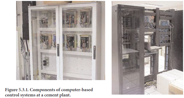
The topic of “Remote Access and Control” in a cement manufacturing facility may initially create apprehension immediately bringing to mind a pyroprocessing line in operation without any direct control. Is this far-fetched and impossible? Controlling a pyro-line from a remote site might currently be thought of as unfeasible, but in 10 or 20 years it could be a reality. It was not too long ago when the “burner” who took his post on the burner floor controlled the pyroprocess system. Then came the innovation of the centralized control room. Over the last few years, central control rooms have been located out of sight of the kiln. Currently, control rooms are being sited farther away from the pyroprocess line. Technologies are advancing in areas of computer hardware and software, communications, and industrial networking. These components are becoming the heart of the control systems and are shown in Figure 5.3.1. The idea of remote control is gaining momentum, and like other innovations, it is being advanced in small, manageable steps. This is a subject that is rapidly changing as improvements in communications and computer technologies continue to be made (Vidergar, 1999). This chapter will summarize various aspects of remote access and control of systems currently found in cement manufacturing facilities.
INITIAL SYSTEMS
The concept of remote access and control started first with the ability to access software systems from remote locations. In the 1970s there was a desire to have information collected in one loca-tion transferred to a different location. This desire is one of the driving forces behind remote control and access.
The business world embraced remote access as a method of transferring payroll and cost account-ing information from the manufacturing site to the central offices. Custom-developed software programs existed on mainframe computers located in the central office. Software users or clients controlled the programs from remote sites and transferred information from the remote site to the central office.
Communication technology consisted of terminals and modems at the remote site, connected to the mainframe via copper phone wiring, modems, and the telephone companies’ communications equipment. Communication speed ranged up to 2400 baud.
Next, in the 1980s, came the development of maintenance and storeroom inventory systems. These systems enabled the sharing of equipment maintenance information and storeroom inventories between different manufacturing facilities, equipment suppliers, and corporate offices. This decade also saw the beginning of the transmission of process data from the manufacturing site. State air quality authorities began to require that process emission data be transmitted to state offices on a routine basis. This required software to collect the data from the continuous emission monitoring system (CEMS) and send it to computers in the state offices. In these early systems, the data was collected and stored in a data file. This file was then periodically transmitted to the state agency using early file transfer systems. System security became an issue that had to be managed. In the late 1980s, the concept of Computer Integrated Manufacturing (CIM) was also introduced by some in our industry that stressed the need for an expansion of remote access to other areas of manufac-turing (DeHayes, 1989).
These initial systems relied on the user having a terminal in the remote location while all software resided on mainframe computers in a central office. Data transfer was a one-way affair. Security was handled at the mainframe. Advancements in communication and computer technologies have enabled faster data transfer rates. Networking technologies began to arrive. Internet communica-tion protocols such as Transmission Control Protocol/Internet Protocol (TCP/IP) were developed. Modems started to be replaced by hubs, switches, and routers. Equipment now exists which allows local area network (LAN) data transfer rates to 100 megabaud. This is much faster than the 2400 baud rates used 20 years ago. Data transfer rates over the telephone lines increased to 24,400 baud and higher.
In the 1990s, as telecommunications technologies improved, software also advanced to take advan-tage of these improved connection speeds. Eventually,software was developed to allow personal computers arriving on the scene in the 1980s to be connected to each other and the central office.
As personal computer technologies improved, they eventually eliminated the previous generation of “dumb” terminals. The PC became useful as a personal productivity tool as well as a terminal to connect to the software packages installed on the central mainframe computers. Software progressed by improving existing features and adding new ones. Generally, software is becoming easier to install and use. The software developers have improved the human-machine interface through the addition of better mimics and views to the software. One of the negative results of these improvements has been software requiring large amounts of computer hard disk memory to store it and large amounts of random access memory (RAM) to operate it. The combination of improved communication technologies and software has helped facilitate the improvement in computer hardware. The difficulty for consumers is trying to keep up with these technology improvements, and doing so in a cost-effective manner.
CONTROL SYSTEM ADVANCEMENTS
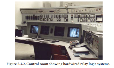
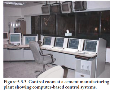
While continued improvements in communications and software occur, improvements to our process control systems are also being developed. Improvements have been realized in processor speeds, graphical interface, and historical data trending. The improvements in processor speeds have allowed the system designers to put more features into a control system. Control systems evolved from the hardwired relay logic systems as shown in Figure 5.3.2 to the computer-based control systems of today, shown in Figure 5.3.3. Once the control systems evolved into the open architecture computer-based systems, the ability to connect to these systems from a remote loca-tion became possible.
Until the mid-1990s, the majority of remote access technology was used in information and busi-ness systems. The world of process control remained leery, with issues including control system security, stability, and reliability high on the list of reasons not to allow remote access. Eventually, hardware and software were developed to provide a secure access, or firewall, to a process control system. The firewall amounted to a protective barrier limiting access to the control system in order to insure that its integrity and responsiveness were maintained.
Once industry began to accept the idea of remote access to the control system, developers of Programmable Logic Controllers (PLCs) and Distributed Control Systems (DCS) began to include this as a standard feature in their system architecture.Many options now exist regarding remote access. Access to the system via dial-up telephone systems or local or wide area networks (LANs and WANs) exists. Access using corporate intranets or the Internet is available. Techniques used to control access to the system range from controlling when the phone line is connected to using any one of the many software packages available for this purpose. Software packages such as PC Anywhere™, Laplink™, Citrix™, and Microsoft Terminal Server™ all can facilitate access to a remote system, and all have features designed to provide some level of security.
Figures 5.3.4 and 5.3.5 depict possible methods for remotely connecting to a system. Figure 5.3.4 shows three methods to connect to a Foxboro™ DCS control system using the telephone system and the company’s WAN.
The first method attempted (labeled as option 1 in Figure 5.3.4) was using a router and modem supplied by Foxboro™. The router and modem were required on each end of the connection. This method was first used in the early 1990s. Connection speeds depended upon the telephone lines, and 9600 to 14,400 baud was considered a good connection. The purpose of the connection was to provide process data at the corporate office for analysis, reporting, and troubleshooting. Although, the idea was appealing, the speed of the connection was at times very slow. Also, only one computer in the corporate office could make the connection. Software existed on the control system to recognize the connection and provide data that were requested by the connection.
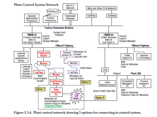
A few years later, as PCs and networking technologies improved, a remote access PC was installed on the control system ethernet highway in the plant (labeled as option 2 in Figure 5.3.4). Software was developed by the control system supplier to allow the PC to have access to the control system network. The PC became a component of the control system while at the same time remaining a stand-alone device. With the new multitasking abilities of computers, the PC was able to manage software specific to the control system as well as provide some control system data to the remote access connections. The connection speeds improved to 26 kilobaud. Laplink™ software was used to handle login security, and now a computer at any location with Laplink™ software, proper tele-phone numbers and access codes could connect to the control system. The connection speed, while not setting any records, did allow for timely data transfer. In addition to the data being passed to the remote site, it was now possible to monitor system operator mimics in real time. The increased speed of the connection allowed more data to be passed thus allowing operator mimics to be viewed remotely. This improved system troubleshooting and process analysis with personnel at the manufacturing site. The limitation to this method of connection was found to be the display manager of the control system only supporting a specific number of connections. Because of the control system design limitations, only a specific number of connections (local or remote) could be made at any one time to the system. This limited the number of remote access PCs allowed to reside on the system, and this method still only allowed one remote connection at a time through the remote access PC.
Again, as networking improved, a third route to the system was established (labeled as option 3 on Figure 5.3.4). This route uses the corporate WAN to provide the connection to the plant. This method of connecting is similar to that of the second option, But, with this method telephone numbers are no longer required. Internet networking communication protocol (TCP/IP) is incor-porated, and each device on the plant and corporate network has its own unique address. By knowing this address, a connection can be made. A portion of the bandwidth on the corporate WAN connection between the corporate office and the plant site is utilized. This connection is always open, but only one remote connection at a time is allowed. The network router and the Laplink software provide login security. Connection speeds increased again as these WAN connec-tions can typically transfer data faster than telephone connections.
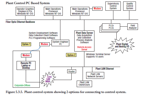
Figure 5.3.5 shows two remote access connections used with a control system based on PC and server technologies. As with the previous control system example, access to the control system using the telephone company and modems provides a basic level of access. Again access is controlled with the connection of the telephone wire along with the software used to dial in.
In this example, PC Anywhere™ or Laplink™ software packages are used to facilitate the connec-tion and provide login security. These connections are typically used in control system trouble-shooting by plant system analysts or the control system supplier. The connection can also be used to make changes to the control system PLC logic. This is a useful feature when the plant is located Remote Access and Control in Cement Plants in a remote area, and a situation exists where program changes made over the telephone are much quicker than waiting for the appropriate personnel to travel to the plant.
The second connection method shown in Figure 5.3.5 incorporates another technology improve-ment over the modem and router connections shown in Figure 5.3.4. The second connection in this example uses a remote access server. The purpose of this server is to provide the remote connections with process data, operator mimics, alarming, and trending functions. Data can now be exported from the control system into a calculation spreadsheet residing on the remote computer. This control system component was designed with remote connections in mind and can support up to 15 remote connections. These connections can be remote to the manufacturing site, or they can be onsite plant personnel who want to view the control system from their offices. All connections are made using the plant LAN and corporate WAN. It is considered a state-of-the art connection at present. Software in the server coordinates the number of connections, acts as a fire-wall to the control system, and serves the requested data to the remote users. Microsoft terminal server or Citrix™ software products can be used to facilitate the connections. In this case, Microsoft Internet Explorer™ is the only software required by the remote user. This eliminates some of the software maintenance required for the system.
COMPONENT EXAMPLES OF REMOTE ACCESS AND CONTROL
In addition to control system suppliers, there are many cement plant component suppliers who are embracing remote access and control technologies in their products. The remote access feature is being used in many products utilized in cement manufacturing facilities including programmable logic controllers, motor drives, overhead cranes, cross belt analyzers, particle size analyzers, kiln shell scanning equipment, maintenance management software systems, and laboratory equipment. Some reasons for including the ability to remotely access these systems include simplifying the troubleshooting process, reducing maintenance costs, reducing repair costs, and improving the time the systems are on line and performing their intended functions.
The common thread across all product lines is that vendors can reduce the costs of maintaining their products and owners can reduce their operating costs with remote access and control capabil-ity. For example, vendors can now assist owners in more preventative maintenance as access can be made remotely and on a set schedule. Equipment suppliers can set up a spare parts consignment program where the equipment user purchases parts as they are used. Equipment vendors with remote access capabilities can help the facility determine which parts are needed when a failure occurs and can provide instruction on the installation of the parts. In this way, owners carry a lower inventory cost, install only the parts truly needed, and are not automatically required to pay for the travel and living expenses of an equipment supplier in the event of a system breakdown. This scenario will become more common as equipment suppliers more fully incorporate the ability to connect remotely to their systems.
Should a problem develop with a system such as a kiln shell thermal scanner, or an analyzer moni-toring the chemistry of the material being transported to a raw mill, the equipment owner can contact the equipment supplier via telephone and describe the symptoms. The supplier can access the equipment in question via another telephone connection or the Internet, and troubleshoot the system as though he were on site. In most cases, a component can be identified as needing replac-ing, a software change can be made to deal with the condition causing the problem, or the owner can be informed of an improper sequence of events that led to the problem. In any case, the prob-lem is resolved more quickly than if a vendor’s representative were required to travel to the site.
Training of employees is another area that benefits from the ability to access systems remotely. When new equipment is installed in a manufacturing facility, there is a certain period of time where everyone holds their breath wondering how proficiently the plant employees will react when the equipment fails for the first time. Also, with systems becoming more complex electronically, and the software used to control these systems being written in newer languages, it becomes more difficult for plant personnel to stay abreast of the new technologies. In new plant expansions, many new systems will be installed with little time to develop plant experts on these systems. When vendors have the ability to remotely access their systems, training on the systems can occur over time, allowing the new material to be absorbed at the employees’ pace.
Figure 5.3.6 shows the internals of a field computer cabinet in a raw material belt analyzer applica-tion. Cabinets can now be supplied to provide an environment in which computers can survive. The cabinets can be supplied with air conditioners and heaters, and the door gaskets can be designed to minimize the amount of dust that gets into the cabinet. Remote access requires a tele-phone line or a plant LAN
connection into a field mounted cabinet, and aPC installed with PC Anywhere™, Laplink™, or similar software to facilitate the dial up connection. Security can be left up to the local software, plant network, or executed manually at the phone connection. There is always someone on site who can plug in a telephone line. This is a fairly typical interface scenario of many re-motely accessed systems.
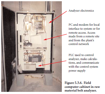
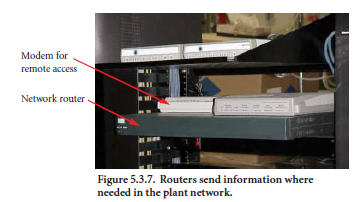
Figure 5.3.7 shows an example of a router that controls access to the plant network. The router is basically a box of electronics which routes traffic to the address for which the information is intended. The router also provides some access security for the network. One end of the router is connected to the plant control system network while the other is connected to the telephone system which connects to the corporate WAN. This device is supplied by many vendors and can be purchased in many different configura-tions. Note the modem connected to the router that provides network administrators the ability to troubleshoot the router from a remote location.
THE NEXT STEP(S)
The information presented up to this point has shown how remote access has been accepted into the cement industry. Within this access, there has been acceptance of remotely controlling plant components within strictly defined limitations, such as troubleshooting. Equipment suppliers are now employing these features during equipment commissioning and other large process modifica-tions (Christensen and others, 1998). In the not too distant future, two areas where the industry can take advantage of the ability to access systems are in process optimization and remotely running facilities.
Remote access and control benefits the cement manufacturer in the area of process optimization. By enabling the various systems throughout cement manufacturing facilities to be connected via plant LANs, the data generated by these systems can now be connected and analyzed more effi-ciently. Until recently, each system in a plant generated a pool of data. There were quality data pools, process data pools, maintenance management data pools, and supervisory system data pools. Sharing data between these various pools was difficult and often required some sort of manual data input by plant personnel. With improvements in database technologies, systems exist which can connect to various data pools and combine the data in one large database system where the source of the data is transparent to the person querying the data. Improvements in corporate WANs, data analysis can be easily performed at non-manufacturing site locations. Companies such as OSI, ABB, Intellution, Rockwell, and many others are utilizing their own database technologies, as well as those from Oracle and Microsoft, to market database systems that will allow manufactur-ers to more efficiently operate their facilities.
At what point should manufacturers begin to consider remote control of cement plants? How will remote control be defined? With the remote access server, it is possible to remotely control the plant equipment from a remote site. As mentioned in the beginning of this chapter, the point of control is moving farther from the process equipment. Central control rooms are providing discrete control for equipment located well out of eyesight of the operator. What difference will it make if the control room were 100 meters from the process equipment or 1 kilometer from the process equipment? Communication between control room and field personnel is usually carried out over radio frequencies with little face-to-face interaction. To seriously consider controlling a facility off site, secure and reliable audio communications will need to be present. There will also have to be some economic driving force present to reward a company for taking this risk. Steps which companies in the cement industry have already taken in this direction include:
• Controlling bridge cranes from a central control room
• Operating a vertical grinding mill system with no personnel over the weekends
• Operating plant laboratories with robots
• Installing supervisory control systems on raw grinding, cement grinding, and pyroprocess systems, and
• Operating product loadout areas automatically.
These steps may be small, but slowly over time, more aspects of the cement manufacturing process
will use some form of remote technologies.
REFERENCES
Christensen, J. T., Terembula, J. W., “Commissioning Cement Plants with On-Line Support from Supplier’s Home Office,” IEEE Cement Industry Technical Conference, Rapid City, South Dakota, April, 1998.
DeHayes, L. J., “Computer Integrated Manufacturing, A case study in the Cement Industry,” IEEE Cement Industry Technical Conference XXXI, Denver, Colorado, May 1989.
Vidergar, R., “Remote Access to Plant Control Systems,” Mill Session Papers, Manufacturing Technical Committee, Portland Cement Association, Skokie, Illinois, 7 pages, September 27-29, 1999.