Contents
Everything you need to know about Automation and Optimization in the Cement Plant
[wpecpp name=”package” price=”75″ align=”center”]
by Michael C. Mound* and Clive Colbert**
This chapter will discuss current and new techniques for automating various aspects of the cement-making process. In all cases, automation is elected wherever cost and value benefits are anticipated to produce a consistent and predictable end product. Optimization is a control expec-tation to the extent possible when automation is implemented according to site, environmental,and plant production rating capacity. Focus is on automating of manufacturing process manage-ment, consistency of production, and the attainment of planned present and future objectives in the modern cement plant.
PROCESS CONSIDERATIONS IN AUTOMATION
Rationale for Automation
Sophistication in automation is a key means of satisfying the exacting requirements of the modern cement plant with respect to productivity, efficiency in utilization of raw materials/energy, quality considerations, and minimal adverse environmental effects.
The advantages achievable via properly executed automation of the production processes encoun-tered in the manufacture of cement are the central reasons for adopting and sustaining the automation effort. In the modern cement plant, automation systems are crucial to the technical performance and the economics of cement manufacturing.All automation systems, to be realisti-cally considered as justifiable investment costs, must meet the basic requirements of achieving predetermined levels of functionality where exacting conditions of availability and operability must be satisfied.
Necessarily, investment in process automation in the cement manufacturing process is usually substantial, and a number of considerations must be taken into account in terms of supplier selec-tion for a successful experience. Expectations from supplier prospects should exceed merely satis-factory levels of quality and sustainability to provide for maximum return on the investment in these important systems. Larger automation systems should ideally be developed for product and system growth in such a manner that the system can be designed to allow for staged build-up. This allows for modification, flexibility, upgrading, and additions over a period of years, according to the pace dictated by the advancement and changing needs of the cement plant over time. That is, newer generations and revisions of the automation systems must be compatible with previous versions to reduce excessive costs in adaptation of existing systems to new facilities and training/retraining of personnel.
The choice of supplier usually dictates the choice of automation system and may or may not be respectively limiting or advantageous, depending on the supplier and the degree of customization for specific individual or multi-plant planning. Depending on the level of technical expertise resi-dent in the cement plant (user) organization, the size of the organization, and its previous experi-ence with automation projects, the selection of an automation system is likely to be made on functional performance of preexisting systems rather than a specific supplier. For optimum overall results and to confirm expectations, the supplier should have cement domain knowledge.
As a general rule, the concept of automation centers on the automatic functional control of continuous and repetitive operations in a process unit, which previously involved manual inter-vention by an operator or operators. Automation is intended to maintain maximum production yields and uniform quality. Evaluation of a successful implementation of an automated system is clearly based on the measurable achievement of these goals in terms of costs of ownership of the system and the resultant value in meeting the established levels of goals.
Types of Automation and Relevant Control Systems
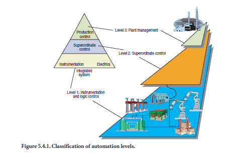
It is common practice to divide automation into three “levels” as below:
Level 1: Digital controllers and complete process controllers with control and logic functionality (PLC systems).
Level 2: Plant control of subprocesses for yield optimization, using advanced sensors (automatic analyzers, etc) directly in the process (raw material characterization, stockpile monitoring, grade control, raw mix control, and optimization, etc.). These would include XRF, XRD, and PGNAA systems positioned on conveyor belts, at process inputs or outputs such as after secondary crush-ers, before and after mills, and so on.
Level 3: This includes automated systems for production coordination/collaboration within the entire process department or the entire manufacturing operation of the plant. The objective is to minimize total costs while maximizing yields and quality control. A fully functional vehicle would include computational capacity for superordinate production control and subprocess simulation facilities. Requirements also involve, at minimum, the capacity for both controlling and monitor-ing control functions simultaneously.
Logic
Digital controller: Programmable Logic Controller (PLC) functionality is today limited to stand-alone systems.
Discrete controllers: Process control using Discrete Controllers may involve superordinate PC’s at central operator stations with command capabilities. However, DCs are less common today, except where simple control circuits are required. In a cement plant wishing to reduce maintenance and sustainability of its systems, DC proliferation should be avoided or kept to a minimum.
Open Control System (OCS)
This system is based on a network concept methodology so as to avoid superordination by computer equipment to incorporate discrete instrumentation and logic functions. Open control systems (OCSs) via networks are efficient means of linking components in the cement plant environment into a stepwise extension.
To build up such an automation system, openness of the system provides ease of interchange of information with manufacturing execution systems (MES) and also with a company’s enterprise resource planning (ERP) system. An OCS combines instrumentation, logic control, and superordi-nate control into a single hardware and software structure (see Figure 5.4.2). OCS also implies openness with regard to technology and makes use of industrial standards and components (example: workstations, Windows 2000TM, Windows NTTM, UNIXTM, IEEE standards, etc).
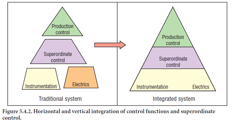
Obviously, process technicians enjoy the advantage of dealing with one single control and logic system for extensions and modification, as is the case with OCS. For operators, further simplifica-tion derives from working with one user interface in place of several. It is also possible to build up automation from single machine controls to an entire plant (and stages in between) when OCS is employed. When specifying an automation system such as OCS, it is necessary to clarify and define the “life cycle cost” (LCC): the cost of using the system for some defined period, such as 10 years. Such a calculation should include costs of modifications, extensions, inputs, and adjustments to increase efficiency of the selected system.
Distributed Control System (DCS)
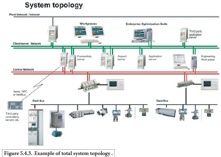
In a distributed control system, control of individual plant sections is assigned to specific process controllers that store all information relative to the process. The database for a particular process section is stored in that section’s process controller.Process controllers are equipped with applica-tion programs via selection of standardized functional blocks and control blocks that are linked together to form control programs. These blocks can range from single logic connections to complete controllers with operator connections. Process controllers have both analog and digital inputs and outputs (I/O) for connections to sensors and actuators of various types. Communications with superordinate process controllers can be accomplished via a Fieldbus, or Profibus. Controllers are normally located close to the process involved for greatest efficiency of operation (Figure 5.4.3).
Emerging Concepts: Industrial Information Technology
Applications of process automation have now embraced the concept of what is known as “Industrial Information Technology,” an information architecture for seamlessly linking multiple applications and systems with historical and real-time data.
Put in other terms, this pervasive concept is designed to deliver advanced, preengineered products that are equally ready-to-use and are reusable across many tasks. These can be in the form of prod-ucts that are simple to configure, install, and move around within the business enterprise, while providing information in context from all data sources.
Industrial Information Technology bridges the gap between industrial and business assets and the information technology (IT) required to integrate these systems in real time.
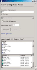
The concept begins with a portfolio of compatible product “building blocks” for power, automa-tion, and information. Bundled with each component is a library of characteristics such as instruc-tion manuals, drawings, configuration tools, etc. supplied in a consistent electronic format. Together, these characteristics – or aspects – form a powerful software shell called an Aspect Object.
As each “block” is physically installed, its corresponding characteristics may be copied and pasted into the system architecture for enterprise integration – the technology –providing quick access to the information required to configure, operate, evaluate, and optimize the device from one interface. Beyond this reusable, “plug and produce” installation, a Windows™-based architecture allows grouping of Aspect Objects in easy-to-navigate structures so that operations, maintenance, or management personnel can effectively manage each component within the context of its larger system. The architecture also facilitates real-time interaction between the aspect characteristics of components to optimize the system in which they are working, and allows easy modeling of new objects into their individual Aspect parts.
In addition, the concept integrates compatible building blocks into application-specific solutions relating to a cement plant’s power and automation.
The Industrial Information Technology Value Chain can be described in two dimensions (Figure 5.4.4).
Figure 5.4.4. Industrial information technology: two dimensions
The Operations Dimension represents all the processes needed to develop, produce, and deliver a successful product. The Asset Lifecycle Dimension represents all tools required to keep the plants ready to produce. The Industrial Information Technology concept defines the collection of infor-mation required to support each plant component as an object containing all the characteristics
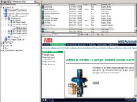
(or aspects) of the device. Aspect Objects can also be finished products, raw materials, or even sales and manufacturing orders. In one scenario, for example, failed plant components and various elec-tric motors might be represented by individual aspect objects, all containing real-time information connected with a particular device. This might include design drawings, control diagrams, mainte-nance information, location, quality information, and configuration information similar to manually scanned documents.
Note that an “Aspect” is not just the real-time information connected with a particular “aspect object,” it also defines a set of software functions that create, access, and manipulate this information. Under Industrial Information Technology, it is possible to implement aspects using many different applications (e.g., MS Word™,MS Excel™,etc.), from third parties. Additionally, it is possible to do this without changes to the applications. It is not necessary for the various applica-tions even to be aware of each other, but they must cooperate to provide an integrated view and functionality of the aspect object.
The individual aspects are enabled by software systems known as aspect systems, each of which stores, manages, and presents information in its own optimal way. Several aspects may share the same aspect system. For example, a report package is used to implement the production report aspect and the quality report aspect of a particular aspect object. In this example, a process graph-ics package implements all the operator graphics aspects such as the graphic display, control face-plate, or display element. On a technical level, the aspects interact with specific software components to provide the functionality associated with that particular aspect.
To see a particular aspect object description, one simply clicks on the description aspect and the software components will connect to and display the correct file.
In the software architecture, aspect systems (like the process graphics and the report package examples given in Figure 5.4.5 above) cooperate with each other without knowing who they are or how many there are. If properly configured, when an aspect system is installed, it registers with the aspect directory (see below) all interfaces that it supports. When an aspect system wants to perform an operation that involves actions from other aspect systems, it ‘asks’ the directory for references to these other systems.
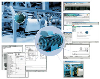
Figure 5.4.5. Real-time lifecycle information for components.
To give an example, suppose an operator wants to change a set value on a particular device. He clicks on the relevant aspect, which is implemented using the process graphics aspect system, and makes the change. To ensure that the new value will change automatically in other aspects, the system must be set up such that the process graphics aspect system will contact the aspect directory looking for references to other aspect systems that need to change the set value.
Thus, the aspect directory is the component that keeps track and stores the associa-tion between aspects and aspect objects.
This is how a change to one component in the factory would be broadcast to all the other system components that need to know.
Once a device is physically in place in the plant, the plant engineer can simply copy and paste the aspect object
(corresponding to the physical device) into the overall system monitoring and control strategy. No matter where each device is deployed, one ‘click’ on the aspect object provides a link to its aspect information. Via the aspect directory, all the other relevant parts of the system are informed of the change.
Automation and Expert Systems
Using Expert Systems in cement process applications is, by now, a well-established procedure. The objective is to allow less expert people to have routine access to the plant’s best expert in a specific field, thereby improving the company’s overall performance by automatically duplicating those skill sets. It has been pointed out that use of a system to automatically ensure correct application of complex rules prevents errors which otherwise may be costly as well as difficult to track and correct.
Closed Loop Expert Systems
So-called advisory systems for process control have been attempted whereby the operator is used to “close the loop.” In such a case, the operator is “advised” to effect a particular change (chemical or otherwise) in process set points to feeders, for example, providing that he accepts the need for the change. This concept permits the operator to intervene and validate the demand as a safety measure. The problem with this approach is the requirement that the operator maintain a consistent level of awareness and degree of attention to the production processes involved. Also, it could permit operator “rubber-stamping” approval, thereby devaluating the safety check procedure intended. To overcome these drawbacks, systems are now totally closed loop. To differentiate between advisory and closed-loop systems, the term “high level control” (HLC) is now in use to describe closed loop expert systems.
HLC systems provide both a supervisory control and process optimization function. The former determines setpoints established for process condition targets (= the mimicking of the “best operator”).
The latter determines the “best” target process conditions to maximize production, minimize costs, and achieve target quality.
Benefits of High Level Control (HLC)
Global estimate: Cost savings are based upon improvement in process efficiency. Normally, between 2.5% and 5% improvement can be expected.
Best operator: Capturing of the best knowledge in a specific plant eliminates less capable opera-tor experiences. This allows for the performance to replicate “best” operator expertise rather than “average” levels. Proof of this can be obtained from historical operator performance records.
Statistical analysis: Estimation of potential benefits can be obtained by examination of the standard deviation of the specific process and the formation of an estimate of the likely change. This is then used to estimate how the process mean can be changed and to evaluate potential changes. An obvious application is to systematically optimize the process control procedures and ultimately track improvements in control results.
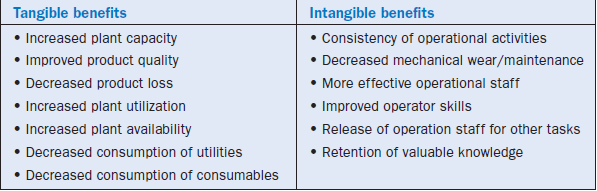
Benefits can be considered as both tangible and intangible (see Table 5.4.1). Tangible benefits are those that are easily measured and quantified, and are used in justification and ROI calculations. Intangible benefits are “softer” and more difficult to measure. Often these intangible benefits are accumulated over time, but can be quite significant.
Table 5.4.1. Tangible and Non-Tangible Benefits of HLC
SPECIAL CONSIDERATIONS
The Goal of Optimization
In the struggle for mating optimized operations with minimized costs, the emphasis is now on balancing the supplier cost factor with enterprise-level consistency and standardization. Thus, contractual arrangements between, for example, energy suppliers to the cement plant can be opti-mized as to costs if they are tailored to the specific site or sites. This is only practical when automa-tion can be implemented to match the plant operational protocols. How can this be accomplished in a realistic manner?
Schedule heavy energy consumption with favorable rates during off-peak times. In this way, the effect of fuel costs influencing production rates can be exploited advantageously.
Schedule specific activities to keep energy bills low where possible. Automated tracking and adap-tation to the energy cost constraints can accomplish this aim.
Reconciliation of consumption of fuel with a production database can automatically be integrated with specific contractual data to optimize cost factors. This is effected with “state of the art” algo-rithms.
New contractual conditions and fees can be then negotiated with the supplier.
Begin with specific departments (e.g., the mills) and extend the concept to the entire enterprise.
New Key Areas for Automation
Several years ago, the measurement favored for measuring the burning zone temperature (BZT) was NOx.This was partly because many kilns used direct-fired coal combustion systems, which gave a very good NOx signal due to the excellent combustion conditions created with such a firing system. With the increasing use of indirect fired systems and low NOx burners (causing localized reducing conditions which destroyed the NOx), it was found that the NOx could not always be relied upon to give a good measurement of burning zone conditions. Therefore, two instruments are commonly used to measure BZT on-line: kiln torque measured by kiln amps and a burning zone pyrometer measurement.
In recent years, a combination of kiln amps and pyrometer has increasingly been used for measur-ing the burning zone condition for use in kiln control. The kiln amps and pyrometer tend to have different characteristics because they measure different aspects of a kiln’s condition; the kiln amps measures the fluxing state of the material in the kiln and the pyrometer measures the BZT. By combining them, it is possible to attain better signals for kiln control than using either one or the other. For example, when the kiln is either very hot or cold, the kiln amps signal is usually the first signal to change.
The advantage of using a pyrometer is that it has an absolute temperature whereas the kiln amps signal gives a relative measurement of the kiln condition that changes with the coating. The absolute temperature of a pyrometer means that its setpoint with respect to kiln control does not need to be changed frequently by the operator, whereas the kiln amps setpoint varies from day to day on most kilns. The kiln amps signal measures the state of the fluxing feed in the kiln and can give an earlier measurement than the pyrometer, which gives a combined flame, feed, and wall temperature. Further, the pyrometer can sometimes be the leading indicator; it has not been estab-lished as to the consistent leading indicator (this can change from kiln to kiln or from time to time on the same kiln). While both NOx and pyrometer give an absolute signal for control purposes, a pyrometer is also much more reliable compared to NOx, meaning that the pyrometer provides a good reading of BZT.
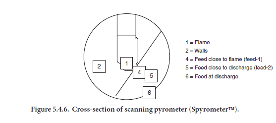
In the past pyrometers have sometimes been viewed as glorified dust meters but this perception has changed with the introduction of the scanning pyrometer (Figure 5.4.6). This novel imaging pyrometer combines a video signal with temperature measurements, permitting the visual moni-toring of the burning zone by the operator and allowing measurements of temperature at six different locations within the field of view.
There are proprietary expert systems that have proven valuable in optimization of the pyroprocess-ing of cement. These systems can help in reducing cost, increasing production and refractory life, improving and stabilizing clinker quality, enhancing reliability, reducing emissions, and increasing operator efficiency. Added benefits have been found when the scanning pyrometer provides input signals to the expert system. At one plant, a 3% increase in production has been attributed to this combination using the pyrometer signals as the principal BZT parameters. The possibility of using multiple zones to define the burning zone temperature provides a more robust and stable signal for kiln control. The weight of the scanning pyrometer is always equal to or higher than the weight of other sensors. Finally, the ability to observe where the measurements take place improves confi-dence in the measurements. This type of new technology is expected to benefit the majority of cement plants.
OPTIMIZATION AND AUTOMATION
Fuels
Currently, the use of an increasingly varied mix of alternative fuel sources by cement plants have been growing. These sources may include solvents, plastics, wood, vehicle tires, etc., in addition to the more traditional combustion materials (coal, oil, natural gas). The motivation for increasing their use is a combination of the environmentally friendly aspect of alternative fuel source usage and the low or negative costs of waste fuels. The idea is to burn as much of the waste fuels as possi-ble from a cost standpoint while controlling the technological requirements of the cement manu-facturing process and undesirable environmental consequences. An important constraint is the final clinker chemical composition as well as associated gaseous emissions.
Optimization requires adaptive calculations of the heat energy required to convert raw meal into clinker. Variables that must be taken into account to address fuel impact on burnability include kiln operating conditions, changes in clinker types, and even atmospheric conditions. Algorithms used in automated optimization schemes must be such as to account for emission limits imposed by legal requirements and predicted resultant levels. The outcome is influenced by stack gas clean-ing, with respect to efficiencies of the devices employed, and the efficiencies of the combustion (oxygen requirements) expected with the alternative and traditional fuels mix. The conversion rate of the raw meal (pyroprocessing to produce clinker), feed rates, production costs, and kiln constraints all play roles in the optimization and automation process (i.e., maximizing use of low-cost fuels with technological and environmental constraints).
An automated approach must comprise a dynamic means of balancing cost factors with changes in fuels, waste, raw meal quality, and manufacturing constraints. Thus, satisfactory implementation includes shifts in availability of alternative fuels, the use of traditional fuels when this occurs, and the maintenance of acceptable clinker quality and production while monitoring profitability of the manufacturing process. These various factors have interactive effects on one another as well as combined influences. Data interchange, reconciliation, and integration of information are required to provide profitable solutions to manage these dynamics.
Cement Process Optimization-Mills
Scheduling of the cement mill in most cement plants is normally managed by the operator in charge, without the aid of optimization tools. Since this operation varies according to the number of mills, grades, and silos, the issue is a complex one. Further, each plant has different operating constraints, and variations in electricity costs/tariffs, making on-the-spot choices by the operator unlikely to be optimal ones. Additionally, some operators choose to keep silos full in anticipation of satisfying sales demands. This normally means scheduling full production overnight (lowest power tariffs), and that day production will be indiscriminate, targeting full silos as the day’s goals without regard to actual need. Unless this resultant capacity is really required, the additional inventory will be without the benefit of balancing costs of production with revenues.
Optimal scheduling of cement mills operation can be achieved based on a mathematical approach that can minimize costs of power purchases and the risk of producing low-grade cement.
All of the above, of course, must comply with constraints resolution in an interdependent and consequential manner to be effective. A satisfactory algorithm addresses the daily or weekly production schedule (quantity of each grade to be produced on each mill) and commitment of production to accomplish this end on an hourly basis. Shipments, storage, and costs are addressed to meet sales fulfillment on a typical daily basis. This also must balance flexibility with limits on daily silo levels so as to account for potential increases in sales potential which may exceed daily forecasts. This most important issue is a subject of current optimization and implementation work being carried out and improved upon by solution providers.
Information Systems (IS)
Many Open Control Systems (OCS) have supplementary advanced functions for handling infor-mation. This type of arrangement may include facility for computations, reporting, acquiring and storing (long-term) of process data, back-up storage of applications functions, and Statistical Process Control (SPC). Additional functions required may include a (logically) structured database (DB), alarm and events handling, and maintenance support tools. The latter are used to inspect and formulate parameters and DB content. Routines are set up for alarm and event reporting, stor-age of messages (with comments), and time stamping, all needed for the detection and diagnosis of faults which can also be done via the plant network.
Figure 5.4.7. Information systems connectivity using thin clients.
Connection of IS requires access to a control network or plant network, based on an established standard (Figure 5.4.3). A network of this sort receives information from subprocesses which are then processed by the IS computer. An open IS based on a workstation or minicomputer can implement “off-the-shelf ” open market software for purposes of simulation, optimization, and production planning. Any useful IS must also be flexible enough to function continuously for routine operations in the process-based applications found in the cement environment. Thus, control room displays can be adapted automatically when plants are restructured and modified in some way or other. Phased modifications can be evaluated to determine simulated consequences prior to implementation so as to reduce stoppages and other disruptions in the work process flow. The end result is better deployment of resources and improved (increased) production efficiencies.
DATA INTEGRATION CONCEPT
The process measurements accumulated over time by the information source system result in a huge amount of data. Often these systems (or point solutions) are linked through a company-wide network and access is provided to everybody by using, for example, web-browser technology. This alone is not sufficient to achieve real integration. It does not bring coherency and consistency. Nor does it avoid duplication of data, inputting, etc. Analysis on interdependent data is not possible.
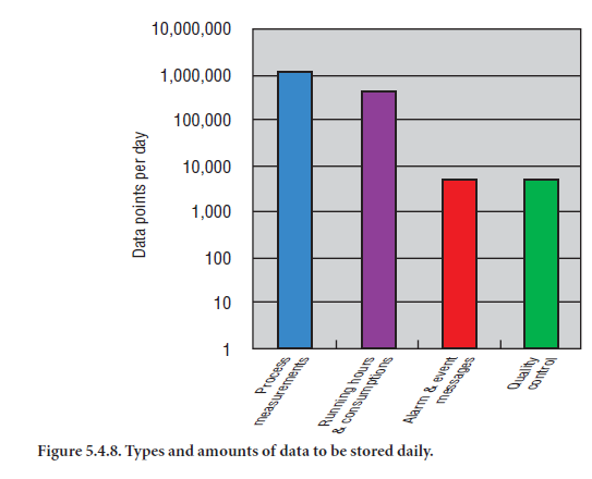
Figure 5.4.8 shows typical amounts for different data of a cement plant that are stored daily. The data is also consolidated for uniform and easy access and analysis of stored data.
Business Process Versus Manufacturing Process
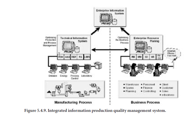
The administrative work of modern companies has already moved to a new era of IT systems. Integrated ERP (Enterprise Resource Planning) systems have replaced the practice of numerous legacy systems with high maintenance costs. Currently, integrated ERP systems are used almost exclusively, and the advantages are significant. Data is entered and maintained only once. Duplication of data is avoided and cross-functional use of data is an implied advantage in the concept (Figure 5.4.9).
The concept of managing the necessary information for manufacturing process optimization is similar to the established and proven solution for business process optimization: the fully inte-grated ERP system.
The vital feature in this concept of production process data is the full integration of the system for the data collection, storage, and analysis. The seamless integration of all data types from the differ-ent data source enables the system to convert data to useful information with a larger context value. Correlation and interdependency can be shown with powerful analysis tools. The Information Production Quality Management System (IPQMS) provides mechanisms and tools to validate, correct, and reconcile data. This enables fast and effective input to enterprise wide reporting (EIS) and to the ERP system. In addition more effective support for daily production, quality, mainte-nance, environmental, and management functions is provided. The IS bridges the gap between the real-time data environment (instrumentation, control systems) and the transactional data environ-ment (ERP). To illustrate the solution, the complexity, and the benefits of an integrated IPQMS, theexample of production accounting is further elaborated upon. It is just one of the functional areas that shows a clear case of the significant benefits enjoyed from this integrated concept.
CEMENT PRODUCTION ACCOUNTING
Typical Application in an Automated Cement Plant
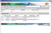
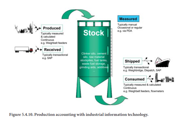
Cement Production Accounting, as an application in Information Management, addresses the most uninteresting, complicated, and time-consuming regular activity, after data collection, in production management, i.e. balancing production figures. An automated world is imperfect due to sensor errors: limited measurement accuracy, calibration drift, transient accumulation, occa-sional malfunctions; and human error: rounding of numbers, spillage, and incomplete calculation and implementation practices. Production figures inevitably need balancing and reconciliation. Production balancing is making the collected figures match with reality and making them coherent within and between the different systems in a typical heterogeneous environment (e.g. point histo-rians, ERP, dispatch systems, sales admin systems, etc.).
In addition to production balancing, a further key in production accounting lies in the administra-tion of received, consumed, produced, and shipped materials (Figure 5.4.10). Through advanced stock tracking mechanisms, it is possible to deliver accurate and coherent information, associating real-time and transactional data from different sources.
LABORATORY AUTOMATION AND INTEGRATION
It would be appropriate to devote a few paragraphs to the subject of laboratory automation/robot-ics, and the overall concept of that automation entity and its role in cement plant integration. The quality aspects of analytics and how they provide data for cement plant management and control have been covered in another chapter. Here, we focus on the automation function.
Quality and quality control are frequently used terms within the cement industry. The multiple functions of the cement laboratory are to provide quality assurance for production and to input data relative to time-sensitive process units so as to optimize the consistency of the plant output. Some larger operations also perform research with an array of sophisticated equipment for evalu-ating alternative materials and fuels for the plant. Additional necessary functional responsibilities may include testing and verification of compliance for environmental reasons important for meet-ing permit limits of emissions and trace contaminants in effluent waters established for specific production levels. Where related plants have different laboratories with different capabilities, there may be a need for occasional or constant linking for specific sample analyses. Finally, some cement plants have commitments to provide analytical data to their associated concrete plant laboratories for special sample paths through more than one series of analyses in divergent applications or for multi-plant standardization. Therefore, the laboratory plays a decisive role in the quality control and assurance program of any cement plant enterprise.
There is a definite trend to increase automation in quality control procedures in the cement indus-try. The degree of automation can vary from individually automated analytical equipment to more or less complex integrated on-line systems. Several reasons which explain the motivation for the increased interest and need for automation in the laboratory. These include:
• Minimization of human error
• Consistency in sampling
• Consistency in sample preparation
• Optimization of existing or new equipment
• Reduction of staff required to perform repetitive tasks
• Reduction of need for “round-the-clock” human presence
• Reduction of labor costs
• Maximization of capabilities
An integrated laboratory automation system provides:
• Improved accuracy of analysis, and faster sample handling and analysis cycles for increasing the consistency of intermediate and finished products throughout the manufacturing process.
• Flexibility of repetitive routine and non-routine tasks, relieving the tedium and potential for error from laboratory staff.
Concept of the Automated and Integrated Production Laboratory
The entire process of sample collecting, identifying, splitting, dosing, transporting, preparing, analyzing, and logging results can be reduced to desired degrees of automation. Points in the cement manufacturing process are identified as to frequency of required analysis and placed in a “job task log” for collection and transport to a central laboratory. Combinations of full or partially automated sample handling and preparation form the initial phase of the “work plan.” Schematic outline of the lab automation and integration in a cement plant is shown in Figure 5.4.11.
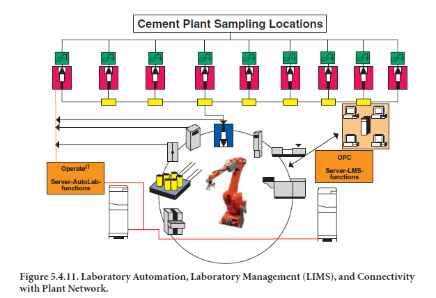
Samples are taken at site-specific predefined intervals and locations and dispatched in loaded closed containers (carriers) via a network of pneumatic tubes to the laboratory for analysis. Samples are identified with a unique number at this point that becomes the means for tracking for analytical or historical purposes. Samples are then automatically split and dosed in aliquots of 200-500gm and loaded into a ruggedized and reusable carrier. This operation is controlled and moni-tored by a PLC/DCS system.
Once received in the laboratory, a robot picks the sample carrier up in an automatic sequence to open, empty, clean, and return the carrier to the respective plant sending station. The sample is then divided (split) for analytical purposes. In a less than fully automatic laboratory, some or all of the steps may be manually implemented.
In the case of full automation, the robot then loads the array of preselected laboratory preparation equipment. All necessary tasks are fulfilled within the laboratory, according to the type of material, the sampling method, and the type and sophistication of the laboratory equipment installed. The configuration of lab equipment (grinding mills, presses, fusion machines, X-ray analyzers, etc.) also depends on the type and quantity of samples taken per hour for analysis. In some plants up to 500 samples per day are taken, although capacity restrictions for the specific lab may require queu-ing for sequencing of analysis.
Where throughput demands are a priority, the automated lab version may be arranged to have higher capacity via redundancy in certain equipment. For example, if the pulverizing step consumes too much time for the sample quantity that must be converted to pressed powder tablets, a second mill (or even a redundant press) may be included. It is worthwhile to note further that individual component equipment may be isolated from the robot circle, compact version offered by some suppliers or even a track/linear configuration, for either servicing or upgrading without disturbing the automatic feature of the system, thereby preserving its contribution to consistent quality benefits.
Samples are sequenced and controlled for analyses by a variety of different equipment, depending on the needs and routines of the specific laboratory. These will include, but are not limited to, instru-mentation such as XRF, XRD, XRF/XRD combinations, Laser-Granulometers, Colorimeters, etc. Results are transferred via serial links to the knowledge management and LIMS systems. Options exist for raw mix proportioning, for example, that can monitor and control mill feed for raw meal production via various control techniques. Planned replacement or upgrading of existing equipment can be scheduled at the option of the lab manager without sacrificing laboratory operations.
In the event of laboratory equipment breakdowns, automatic alarming can be integrated. When back up equipment is installed (two mills, presses, etc.) automatic change over to the remaining systems permits uninterrupted functioning of the laboratory. Relevant laboratory data are stored for long- and/or short-term analyses, quality control reports, etc. By automating the laboratory and integrating its function into the cement plant enterprise, greater access to real-time control becomes routine.
LIMS (LABORATORY INFORMATION MANAGEMENT SYSTEM)
LIMS: Dual Integrated Functions
Although addressed elsewhere in this book, LIMS deserves special comment within the context of automation. Lab management requires advanced means of documenting quality information to make it easily accessible in a transparent manner so it can be of overall use to a cement production enterprise. Operations can, via a properly configured system of the type described herein (Industrial Information Technology and Aspect Objects), have timely access to even off-line infor-mation on the process, thereby increasing actionable improvements.
Related to this is the basis for day-to-day direct process and quality control means by which improvements can be effected. Included are various functions such as both automatic and manual data acquisition, data validation, data consolidation, long-term storage, calculations, sample logging, sample status reports, joblists, standard and special compliance reporting,
trending/graphing, and options for Excel™ and SPC. The ability to make process quality informa-tion centrally accessible is critical in a modern cement plant to meet production costs and quality objectives. Efficient running of the business reaches back into process and production, which, in turn, rely on laboratory/quality data. Total quality optimization finds its solution in the Industrial Information Technology architecture. This is because this quality information is used for:
• Feedback to process control
• Adapting production quality planning according to raw material and fuel analyses
• End-product analyses for compliance purposes.
Sharing of analysis equipment between several production labs is supported by LIMS. This allows for on-line collaboration with other laboratories in a multi-plant enterprise, which results in major cost savings and can be part of the overall plant strategy.
SUMMARY
Process control based on Industrial Information Technology incorporating OCS has many advan-tages, including the simplified combination of logic and control in a single system with open archi-tecture. Automation of control can be distributed entirely to process controllers that serve separate process sections. Communication between process controllers and central operator stations is via control networks. Integrated systems provide, via operator stations, a unitary interface with processes, thereby simplifying adjustment of process incidents to increase cement manufacturing production yields.
Relating this to cement production laboratories, LIMS (Laboratory Information Management Systems) are specifically employed to manage process quality information according to proven lab practices. When incorporated into an Industrial Information Technology architecture, full integra-tion can comprise enterprise-wide knowledge management for process, production, and mainte-nance management. Accordingly, the cement-specific LIMS addresses two key areas in daily laboratory management: information management and laboratory task management.
Automation of the reconciliation of production on a consistent, error-free basis is the province of an integrated production accounting system. Yet another instance where the use of intelligent integration provides collaboration between production, process, and quality (laboratory opera-tions) in the modern cement plant is where Aspect Objects and enterprise-wide knowledge management merge.
REFERENCES
ABB Industrial Manual, ABB AB, Wallin & Tryckeri AB, Lund, Sweden, 1998.
Alsop, P. A., et al., Cement Plant Operation Handbook, Tradeship Publications, various editions.
Clark, D., Expertly Controlled, World Cement, January, 2002.
Gallestey, E., and Colbert, C., Economic Optimization, in progress.
Herzog, Urs, and Hantikainen, R., A Real World Innovative Concept for Plant Information Integration, IEEE/PCA Annual Meeting, 2002, Jacksonville, Florida.
Imaging Systems Group, Cement, Quadtek, www.quadtek.com/VisCement.App.htm, October 17, 2002.
IndustrialIT, ABB Website, www.abb.com, various, October-November, 2002.
Thermoteknix Systems Limited, Cement and Lime Industries, ww.thermoteknix.com/areas/cementandlime/default.htm, October 17, 2002.