Contents
Everything you need to know about Operational Considerations
[wpecpp name=”package” price=”75″ align=”center”]
by Don Stafford* and Anya Gill**
During recent years, cement companies have come to realize the necessity and the applications of on-line control and optimization techniques and the enormity of the associated operational bene-fits during cement manufacturing. Effective material processing, proportioning, and product char-acterization coupled with a controlled kiln operation as attained by optimization and control techniques are fast becoming the key to a stable, more efficient, and productive cement operation. The introduction of such optimization techniques has resulted in maximizing production and significantly reducing downtimes and refractory costs. This chapter discusses techniques and tools that can be used to ensure that the cement-making process is controlled as closely to optimum as possible. Both traditional methods and advanced state-of-the-art technology employed at various stages of manufacture in modern cement plants are covered.
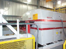
Figure 5.1.1. Prompt Gamma Neutron Activation Analyzer (PGNAA) used for on-line determi-nation of material composition.
THE CONNECTION – QUALITY CONTROL AND PROCESS CONTROL
From quarry to finish mill, consistency of quality is heavily dependent on the nature of the materi-als used and how well each process is controlled. Operational steps required in producing cement at a modern plant are adequately described by Alsop (1998).
At the quarry, a detailed mining plan with adequate core drilling data is necessary to ensure that the major component(s) will meet raw mix requirements. If appropriate, preblending of raw mate-rials is effected which requires accurate control of component proportions. In this regard, the use of advanced technology such as the Prompt Gamma Neutron Activation Analyzer (PGNAA), as shown in Figure 5.1.1, is gaining ground. Operating procedures used after crushing should ensure that size segregation is minimized to prevent major chemical changes or cycles as the pile is reclaimed.
In the raw grinding process, it is necessary to control chemical composition and fineness, as both will affect the burnability of the mix and the quality of clinker produced in the kiln. The number of parameters or potential compounds (such as C3S, C2S, C3A, C4AF) that can be controlled is one less than the number of mill feeders available. These targets must be adjusted to compensate for chemical contribution of residual materials in the kiln, such as coal ash. The feeders must control closely to the target rate without incidents of starvation or flushing. This will result in consistent chemical composition and stable grinding circuit operation.
The importance of good process control at the kiln is obvious. Good quality clinker is only produced if the correct temperature profile is maintained from the preheater through the kiln and in the cooler.
In finish grinding, additive control (gypsum, grinding aids, limestone, and pozzolans) must be consistent and accurate. Correct particle size distribution of the final product is critical to its performance and can only be achieved if circuit operation is very stable.
SAMPLING AND ANALYSIS – TRADITIONAL METHODS
At all selected sampling points it is very important to make sure that the sample collected is as representative of the entire stream as possible. The larger the maximum particle size at that point, the bigger the sample needs to be. Guidelines for sample size and reduction for analysis can be found in the standards of the American Society for Testing and Materials (ASTM).
Raw Materials
In addition to the quarry sampling mentioned earlier, a quality assurance program should be implemented for all raw materials brought in to the plant. A system such as ISO 9000 (International Standards Organization) can be very useful for this purpose. Its elements include purchasing, inspection and testing, and control of nonconforming product. All necessary quality specifications should be defined in a purchase agreement. It is best to put the responsibility of quality assurance on the supplier, and then verify it with spot checks of your own.
In Process and Finished Products
Several sampling points in the cement manufacturing process are considered key for good quality control/verification. Table 5.1.1 lists suggested locations and frequencies.
Table 5.1.1. Recommended Sampling and Testing Frequencies
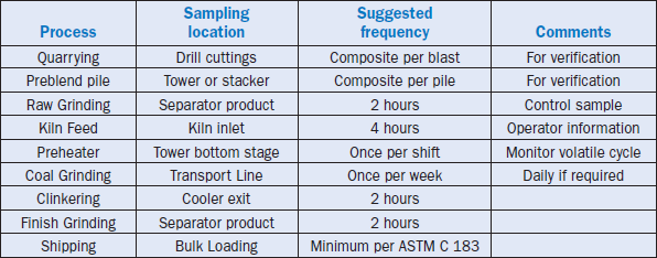
There are many different types of automatic sampling systems available, and it is important to select the correct sampler for the application. Crosscut samplers traverse the entire stream of mate-rial, which is usually desirable. Pneumatic retractable tube samplers can be used in transport lines and other locations but must be placed so that particle size segregation does not affect the sample. Vertical transfer points usually give the best chance for a representative sample, and collecting samples from airslides should generally be avoided.
The sample size usually has to be reduced to the appropriate quantity for the test(s) to be performed on it. A riffle splitter should be used for this purpose, similar to that described in ASTM C 702.
Most of the analytical test methods used in cement quality control are detailed in ASTM C 114. There are also some additional specific tests used mainly for troubleshooting quality problems (see Section 8).
OPERATIONAL CONSIDERATIONS
Both process and quality control strategies should be developed with the objective of maximizing throughput while maintaining the desired product characteristics to meet the customer’s needs. Most plants have automated computer control systems that provide frequently updated process measurements, such as temperatures, pressures, and material/gas flows. Quality checks will come at intervals similar to that described in Table 5.1.1, or more frequently if some type of on-line analysis is used.
The key quality parameters should be identified at each stage of the process. These are the ones that have a direct impact (statistically verified) on the critical product characteristics of the finished cement(s). Decision-making tools such as Statistical Process Control (SPC) are very useful in developing and implementing a systematic approach to optimizing control.
Raw Milling
Traditionally there was not a lot of emphasis placed on either raw milling circuit control or mix chemistry control. Usually the raw mix consisted of a small number of components such as lime-stone, clay or sand, and an iron source. In wet process plants, blending in slurry tanks allowed for effective correction to targets before pumping to the feed tanks. In dry process plants, attempts were usually made to design feed silo blending systems that would reduce mix variability by as much as 5:1 ratio or even more. This aeration process consumed a lot of power and was seldom very successful.
Recently the number of components has increased, often including by-product or waste materials such as flyash, bottom ash, spent sands, slags, and so on. As a result, control has become more complex. At the same time, the trend has been to reduce feed silo capacity and blending efficiency, both in the interest of cost savings. These factors, together with stronger emphasis on reducing mix variability for stable kiln operation, have called for better techniques in raw milling process and quality control. Moeller (1997) has reported a detailed account on the influence of raw material and fuel with respect to the burning process and the quality of clinker produced.
Raw grinding is accomplished with either a ball mill or a vertical roller mill. Usually these are air swept with hot kiln exit gases to dry the wet raw materials, or sometimes the feed goes directly to the separator to be dried before entering a ball mill. Both chemical composition and particle size are very important, and some type of automated circuit control is highly recommended as a means of keeping these on target. Process control in a ball mill monitors several selected parameters to determine the appropriate fresh feed rate. Typically these are circulating load level, mill motor power, sound level, temperatures, and elevator and separator power. For roller mills and air swept ball mills, inlet and outlet gas temperatures and mill differential pressure are also important. APID control loop is commonly used to adjust feed, although other methods such as “fuzzy-type logic” or adaptive/predictive control may also be used.
Many raw grind circuits are now equipped with dynamic separators which use variable speed to control fineness of the product. The required fineness for burning depends on specific materials and kiln conditions, but commonly targets are about 80% passing the 75 micrometer sieve and 99% passing the 300 micrometer sieve.
Other quality targets to be used depend on the type of clinker being produced and the number of raw material components. The number of targets is limited to one less than the total number of raw materials being controlled. C3S, lime saturation factor (LSF), C3A, silica ratio (SR), Fe2O3, and alkalis are some of the quality measurements that may be used for control.
Gathering representative samples for raw meal control offers several possibilities that can fit within a variety of operating philosophies. There are distinct advantages and disadvantages of sampling before or after the raw mill, using centralized or field-mounted equipment that must be considered in relation to overall quality objectives.
PGNAA Before the Raw Mill
PGNAA (Prompt Gamma Neutron Activation Analysis) emerged as a viable technology for the cement industry in the mid to late 1990s. The PGNAA analyzer unit (as already shown in Figure 5.1.1) is mounted on the belt feeding the raw mill. A neutron source is positioned under the belt. As material passes over the source, it is bombarded with neutrons. The source is either a neutron generator or a radioactive isotope, typically Californium 252. The neutron strikes atoms of the bulk material on the belt and creates an excited state followed by emission of gamma radia-tion. The gamma rays are released within nanoseconds, making this the closest analytical tech-nique to real-time. Typically, units are set up to scan for a period of 1-2 minutes, then generate an average result and make feeder corrections based on 10 minutes of data.
The advantage of PGNAA over conventional methods is that no sampling or sample preparation time is required, thus eliminating sampling errors and yielding real-time chemical analysis of the bulk material. The analyzers are typically priced at around 40%-60% less than a fully automated centralized laboratory analyzing only raw meal.
A disadvantage is that it provides only a chemical analysis of the atomic composition and as such cannot provide any indication of fluctuations in silica grain size that would directly affect burn-ability and grindability. Because the physics of the neutrons lead to better overall repeatability and analytical performance on bulk material before the raw mill, dust returned to the process after the raw mill cannot be analyzed. For some plants this may be a significant consideration. And,although a minor point, it is limited to only one analysis point, making future expansions of sampling points impossible.
At-Line Analysis
There has been renewed interest in the past few years in analysis at-line. This does involve sample extraction but it is closely coupled to the process point and samples are not sent to the laboratory for analysis. Some at-line systems incorporate sample preparation such as grinding and pressing. Pricing of at-line units range from 20%-100% of the cost of an on-line system.
An advantage of at-line analysis is the variety of techniques available. These systems can range from rough indications of raw meal chemistry that can be automated and double checked with periodic analysis in the laboratory to larger, more precise (and hence more expensive) units that begin approaching the precision and repeatability of the centralized laboratory. The challenge with putting analytical equipment in the field is creating a robust system that can still provide the correct analysis in a manageable package. One of the major concerns in moving raw meal analysis to the field is dealing with the sample preparation.
In the laboratory, samples are normally ground to overcome particle size effects in x-ray analysis. The fusion technique is used to overcome matrix effects. For raw meal control, some at-line systems offer pregrinding and pellet pressing in order to obtain meaningful control information.
At-line systems can be used for a specific analysis location, and some can be applied to two sampling points if they are physically close enough. The variety of systems on the market also offers other analyses in addition to chemical analysis, such as particle size distribution. It must be noted, however, that in the move back to decentralization, these units will require maintenance in the field and should be installed in a way that safely and conveniently allows proper preventative maintenance as well as access for repair.
CENTRALIZED LABORATORY
This traditional method of bringing samples to the laboratory has benefited from the developments in automation technology. Manual sample gathering, preparation, and analysis is not only time consuming but fraught with potential errors. A benefit of automation is to minimize human error in the sampling and analysis. Automation can be handled in a variety of ways to suit plant needs and budgets. Some plants may choose to fully automate the quality control function while others may prefer to automate it in sections. The systems available on the market allow for this flexibility.
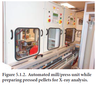
The options include automating raw meal analysis with sampling, sample homogenization and transporting the same to the laboratory. Automatic or manual receivers will accept delivery of the sample. Various degrees of automation are available from a traditional manual process to semi-automatic mill/press units to robotic units that move the sample from preparation through analysis on XRF, XRD, and particle size. It is also possible to automate just the sampling, with manual transport to the laboratory. However, the plant then cannot take advantage of the increased sampling possible in fully automated sampling/transport systems. A typical auto-mated mill/press unit used in repairing pressed pallets for XRF analyses in a centralized cement laboratory is shown in Figure 5.1.2
While typically the highest in initial investment costs, the automated central laboratory does provide the capability to expand the use of the same laboratory equipment for all sampling points throughout the plant as well as the occa-sional manual samples that may be required.
Raw Meal Control
The critical function of raw meal control is the implementation of corrections indicated by analy-sis through control of feeders. Both timing and amplitude of feeder adjustments effect compliance to target. Of the various methods for sampling such as, on-line, at-line, and centralized laboratory, not all have full control capabilities.
On-line PGNAA systems typically do have full control of component proportioning, and on-line particle size distribution systems have some control that can be incorporated into a plant control system. At-line systems may or may not have raw meal control capabilities. It is important to deter-mine how the analytical data gathered will be used. A simple indication type analysis will rarely have a sophisticated control. Other at-line systems with bench-top X-ray units usually have more complete and complex control packages.
Some of the at-line and on-line systems also take advantage of standardization in computing and are able to communicate through a bus system with either the central laboratory system and/or the main plant control system.
Kiln Feed Homogenization
Aerated blending/homogenization systems are generally not terribly efficient. Typically, they may have a turndown ratio of 2-3, meaning that they reduce the variability by that factor. It is desirable for the kiln feed to have a standard deviation of three or less. Blend silos using air pads or airslides must be carefully maintained for continued efficiency and may be costly to operate due to power requirements of the compressors. Recently the emphasis seems to have shifted from homogeniza-tion to improved raw mix control, especially with the use of on-line control techniques.
Solid Fuel Grinding and Firing
Solid fuel (coal/coke) is normally ground in either a roller mill or a ball mill, with firing systems ranging from direct to indirect. Consistent fuel quality and fineness is required for stable kiln opera-tion. Important fuel characteristics are heat value, moisture, ash content, and often sulfur/ chloride. As-fired coal normally is about 85%-90% passing the 75 micrometer sieve, and has about 1% mois-ture. Since the ash alters the chemistry of the clinker (typically lowering C3S and increasing C3A), the raw mix targets must be set to compensate for the ash. Hardgrove index for grindability may also be important, especially if the fuel grinding system is near maximum capacity. A higher index indicates material that is easier to grind. Moeller (1997) has also reported a detailed account on the effects of raw material and fuel on the burning of clinkers and their resulting properties.
KILN OPERATION
Operation and control of the rotary kiln is by far the most challenging aspect of cement manufac-turing. Accurate and reliable process measurement inputs are absolutely essential in providing information for control strategy decisions. The kiln production rate and burning conditions are generally controlled using feed rate, rotating speed, fuel firing, and induced draft. Temperature and pressure profile from feed tower to cooling fans, as well as gas flow and composition, are all infor-mation that the operator needs to make the correct control decisions. If high-level artificial intelli-gence software is in control of the kiln (operator monitors), then all of these inputs are a must. A program should be in place for regular maintenance and calibration of field instrumentation.
High temperature color cameras and pyrometers are now commonly used to provide the operator with a continuous picture of kiln and cooler conditions, as well as material temperatures. Infrared shell scanners provide a 360-degree profile of exterior shell temperatures from feed to discharge. Loss of refractory or coating is detected immediately, allowing the operator to react quickly and prevent permanent heat damage to the kiln shell. The scanners are also useful in detecting ring formations.
The kiln temperature profile will obviously vary greatly depending on whether it is a wet, long dry, preheater, or precalciner type, and on the burnability characteristics of the feed. Traditionally this part of the process has been controlled by the operator, who has to make multiple complex strat-egy decisions. Recently more automated techniques have become popular, and these are discussed in the Control Techniques Section of this chapter.
Kiln Exhaust Gas Analysis
Exhaust gas analysis has been used for many years as an indication of process conditions and for optimization of kiln combustion. With wet process and even long dry kilns, this was a relatively straightforward process requiring a sampling probe, gas conditioning system, and analyzers. With the cooler temperatures at the feed inlet, a simple tube with an external filter assembly would suffice. Probe positioning was important to prevent mechanical damage and to avoid sampling tramp air leaking in from the seal.
With higher production rates and more aggressive process control required for the preheater and precalciner kilns, gas analysis is no longer as easy. The sampling temperature is well above that tolerated by simple tubes, and the dust load requires more elaborate filtering and probe blowback. Initially a water-cooled probe design was introduced that used water as a means of extracting the sample gas. These systems proved to be rugged and required relatively low maintenance. However, the system had limitations with the dissolved oxygen in the water generating an error in the meas-urements, and the SO2 being completely washed away. Within the past 15 years, the water-cooled probe continued to evolve to allow gases to be extracted on a dry basis. Oxygen is now more precisely measured and SO2 is no longer dissolved, allowing for a full complement of analyses. Oxygen and CO analyses are used for overall combustion control, NO is an indication of the ther-mal stability of the kiln, and SO2 is an early warning of combustion deterioration.
For NO, the analysis does not require all the oxides of nitrogen in order to be valid or meaningful. The operator will be looking for a change in NO rather than a specific value as an indication of thermal stability. The primary oxide is NO at those temperatures. As the gases are transported to the analyzers, they are cooled to remove condensables and filtered. In a flash cooler, most of the water is removed quickly, but it still leaves up to 800 ppm of moisture in the sample, at a typical dew point of around 2°C –3°C. NO and SO2 interact in the presence of the moisture, generating a sulfuric acid mist that continues to form throughout the sample conditioning and analysis system. This acidic mist will condense in tubing and fittings and eventually creep into the analyzer, causing drift and calibration problems.
Some plants experience more serious problems with acid mist than others but most do to some degree. Usually the mist can be taken care of with regular maintenance and periodic replacement of tubing and fittings. However, in those plants facing chronic acid problems, a wet chemical solu-tion is often required. One of the most effective solutions has been to add a hydrogen peroxide drip to the flash cooler to remove virtually all the SO2.While this limits the potential to analyze all the combustion gases, SO2 is in the third tier of analyses at the kiln exit and may be worth sacrific-ing to achieve more stable, long-term analysis of CO, O2,and NO.
Hot-Meal Samplers
Hot meal analysis has the potential to provide timely and meaningful information, but due to the inherent sampling dangers and processing time, this sampling location has rarely been incorpo-rated as a standard element of a quality control program. With the advent of water-cooled samplers and sample transport systems, it is possible to routinely analyze a sample for volatiles and degree of calcination. These tests may be performed on a regular basis (typically once every hour) and used for process control.
In Europe, where energy costs have traditionally been significantly higher than the United States, the alkali measurement is often tied in with bypass control. Rather than leaving the bypass at a fixed rate, the dampers are adjusted to optimize alkali concentration and energy.
Determination and Control of Volatiles
The burning zone of a kiln is extremely hot (typically close to 1400°C). Certain minor compounds and their eutectics boil or volatilize below the burning zone temperature. They are carried in the gas stream to the feed end where they often condense, creating sticky material build-up problems. They also condense on feed particles and are carried back into the burning zone where they volatilize again. This results in a “volatile cycle,” which may cause the kiln to be very unstable and difficult to operate. Chlorine, sulfur, and alkalies are elements that normally contribute to this problem. The bulk of the volatile compounds can be removed with the clinker if the kiln operating conditions are right. However, chlorides (the most volatile) and larger quantities of sulfates must be removed and disposed of using either a gas by-pass system (for cyclone preheater kilns) or bag house/precipitator dust wasting (for long kilns). A raw feed chloride level above 0.015% to 0.02%usually results in the need for dust wasting.
Clinker Cooler
The primary functions of the cooler are to reduce clinker temperature to a reasonable level and recover heat for combustion and drying air. The stability of cooler operation, especially secondary air temperature and volume, has a direct impact on the kiln process control. Therefore, a method of automated control for undergrate pressure, grate speed, and fan flows is necessary. Constantly changing material volume, temperature, and fineness make manual control by the operator extremely difficult.
CLINKER SAMPLING AND ANALYSIS
The key element in applying automation to clinker analysis is obtaining a timely and representative sample. The sampling point is critical to accomplishing the objective. It is equally important to capture a clinker size that has the typical composition of the clinker overall. While a sample volume can be filled quickly with oversized clinker, that clinker rarely is representative enough to be used for general control. Typically the desired size range is a clinker diameter of less than 50 mm. Both at-line analysis and centralized laboratory systems can be used to analyze clinker.
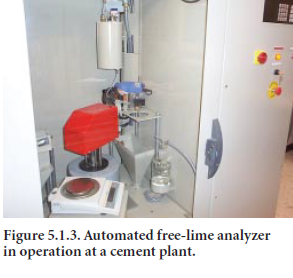
As with raw meal, at-line systems are available to analyze clinker close to the kiln discharge. Analysis is typically limited to a quick free lime test that can be used directly for control adjust-ments. These systems extract the clinker and perform the analysis near the cooler. An auto-mated free-lime analyzer in operation at a cement plant is shown in Figure 5.1.3.
Central laboratory systems require sample transport. A typical sample for raw meal, kiln feed, or finish mills easily fits within the capsule and a repeatable amount of sample can be sent to the laboratory time and again. However, clinker particle size varies, and the material is hot and abra-sive to the sample transport capsule. The sampling system for clinker usually includes crushing and grinding prior to filling the blending container and subsequently the transport capsule. The centralized laboratory analysis usually includes the full XRD analysis of the clinker and sometimes a free lime measurement. Due to the precrushing, clinker samples are not suited for later analysis under the microscope.
Mineralogical Assessment
Recent focus has been on improving material uniformity from the quarry to the kiln. But there are opportunities for automation further in the process aside from just replacing manual tasks with automated ones. By utilizing the advances in technology for sampling, sample preparation, XRF, and XRD (especially in the capabilities of computers), quality control can be further automated.
Rietveld Phase Analysis
Calculation of clinker crystal sizes and brittleness offers a challenge to automating grindability calculations. Traditionally, calculating crystal sizes was done with microscopy using honed talents in a process that required a significant amount of time for sample preparation and evaluation. This process does not lend itself to automation. In recent years, powerful XRDs have been incorpo-rated into the cement plant laboratory. Using the analyzers in traditional ways has only scratched the surface of the capabilities of the XRD units and the data that can be generated with them. Through the use of PCs, applications once confined to universities can now be applied to real world applications.
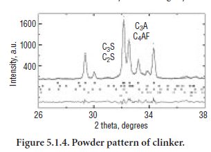
The Rietveld method is one of these techniques (Moeller, 1998). Developed by the Dutch crys-tallographer, H. M. Rietveld, in the late 1960s, it uses basic diffraction principles to calculate the diffractogram of a single or multi-phase crys-talline mixture. This was later applied to the quantitative analysis of the mixtures. Crystal structure databases were established with all the information necessary to calculate a diffrac-togram for a specific application. The program looks at the powder diffraction pattern and mathematically adjusts the phase content based on information in the control file library, until the diffractogram matches the sample. While the method proved effective early on, it wasn’t until computing power became affordable and fast enough to significantly reduce the analysis time that the technique became practical. Moeller (1998) has reviewed in details the Rietveld Method on clinker phase analysis in one of his papers on automations.
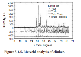
The overwhelming advantages of using the computer technique and employing the power of multiple regression software are that the method is standardless, like microscopy, and overcomes the limitations in traditional diffractogram analysis posed by peak superposition. By allowing the computer to work with the diffractogram and the Rietveld library to find the match, the phase content is calculated.
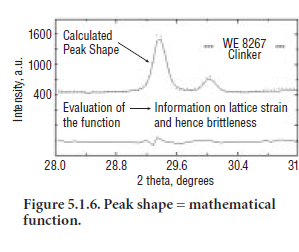
Peak shape and area also provide additional information on the crystal structure of the clinker.
Crystal Size and Brittleness
As the XRD scans the sample and plots the points, the curve can be mathematically described. Based on this description, the Rietveld programs use the peak shape to determine a lattice strain indicating the brittleness of the crystal.
Crystal size has traditionally been determined microscopically. Using the diffractogram generated by the XRD, the average crystal sizes in the clinker sample can also be calculated. The sharpness of the peak correlates to the crystal size. Automating a method of Full Width Half Maximum(FWHM), calculating the average crystal size can be done, but the result is very dependent on sample preparation. A sample prepared for the XRD in a fine grinding mill and pressed into a tablet yields absolutely no information on crystal sizes. A very precise, repeatable sample prepara-tion method must be developed within the laboratory automation system.
The following analyses can be performed with the automatic laboratory using routine clinker samples:
• Alite and Belite Content – XRD
• Alkalies – XRF
• Crystal Size – XRD
• Brittleness – XRD
With the precise, repeatable sample preparation and excellent reproducibility in the XRF and XRD, this data can be used in conjunction with the Rietveld calculations and multiple regression to build models to determine such factors as the clinker grindability in kWh/ton or even to predict 3-day strengths automatically.
Finish Grinding
Quality specifications for portland cements are given in ASTM C 150. Test procedures are in ASTM C 114. Material proportioning and grinding circuit process control are very important to the quality of the finished product. Gypsum content (cement SO3) and mill temperatures are criti-cal to setting properties and strengths. Optimum cement SO3 is determined by ASTM C 563, and it changes with clinker SO3,C3A, and other parameters.
Composite samples are generally tested every 2 hours for chemical content (X-ray), Blaine (specific surface area or fineness), and % passing a 45 micrometer sieve. Particle size distribution has a significant effect on the cement’s performance characteristics in concrete. These include setting time, workability, water demand, and strength. Consistent particle size distribution is achieved by running a constant circulating load and air to feed ratio in the separator.
Particle size distribution can be determined using on-line analysis or a centralized laboratory system. The method selection depends on the overall plant philosophy toward automated control, the number of finish mills, and the analyses required.
On-line analyzers are located in the field and transmit the analytical results back to the laboratory. Analysis frequency is generally flexible, and timeliness is of particular interest in those plants that have minimal silo storage capacity. Since the unit is mounted in the field it is necessary to perform all routine maintenance in-situ. Therefore, installations must be arranged to facilitate safe and easy access.
The central lab approach relies heavily on the sample transport system. Samples are taken over the specified period, blended, and then a portion is transported back to the laboratory via a pneumatic tube system.
Once in the laboratory, a technician can manually process the sample. If available, an automated system can perform sample preparation and analysis, as well as implement control actions for the finish mill. Moeller and Gill (1999a, 1999b) have addressed automation and the application of computer in monitoring clinker grindability vis a vis production at a cement plant.
Automating the particle size analysis system in the laboratory has proven challenging. The dry dispersion technique initially seemed the most appealing, but there were problems with sample residue building up in the unit, resulting in drift over time. The wet dispersion system is used in some cases, even though the alcohol dispersion mechanism requires regular maintenance. Some instruments were de-signed to circulate the alcohol through a routine cleaning and filtering process, and maintenance was reduced but not eliminated. The current generation of dry dispersion labora-tory-based PSD instruments shows more promise with re-peatable, long-term performance. An automated analyzer for determining particle size distribution of cement is shown in Figure 5.1.7.
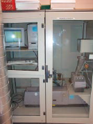
Figure 5.1.7. An automated particle-size analyzer in operation at a cement plant.
Another essential aspect of finish grind control is the addi-tive systems used for proportioning grinding aid, air en-training agents, etc. Accurate flow measurement and control are required to ensure product quality and dry flowability. Grinding aids are most efficient when diluted with water (5 to 10 times) and injected into the feed end of the mill, with air aspiration to disperse the mixture into the load. Dosage rate of grinding aid is typically 0.3 to 0.7 kg per ton (active ingredient) to achieve a pack set index of say 3 or less.
Process and quality control in a finish grinding circuit is also strongly dependent on accurate field measurement inputs. Consistent product quality can only be achieved if the circuit operation is optimized and stable. Indicators commonly used for fresh feed control include: raw material feeder tonnages, mill motor and discharge elevator power; mill sound level, mill discharge temperature and water spray addition rate, separator power, and rejects tonnage. Moeller and Gill (1999a, 1999b) have also reported advances in laboratory automation for calculating clinker grindability.
CONTROL TECHNIQUES
Manual Control
Cement plants built in the 1960s and 1970s were typically equipped with manual control systems. All set points were entered individually through large control panels with dial or thumbwheel-type units. Early computers controlled each component in the system to its selected set point. Limited field analog sensors were available at that time.
Automated Systems
Distributed control systems (DCSs) were introduced to cement manufacturing processes in the 1980s. While they provided automated process control with PID tuning capabilities, the interface and software packages were inflexible. Few plant personnel possessed the knowledge and skills to adapt the packages to changing plant conditions, and add-ons were next to impossible. The transi-tion from multiple control areas to a centralized control room was challenging, as the trend was to less field personnel (the operator’s eyes and ears).
The current control systems of choice are a combination of human-machine inter-faces (HMIs), control software, and field programmable logic controllers (PLCs). They usually include sophisticated his-torical data packages (trending, alarms, operator change logs), which replace the traditional strip chart recorders. These packages have almost infinite flexibility to change graphics and control logic, and the addition of components is relatively easy. A typical central control room showing state-of-the-art automated systems is shown in Figure 5.1.8.
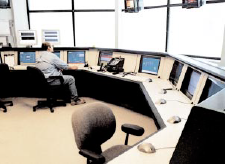
Figure 5.1.8. State-of-the-art automated control room of cement plant.
Expert Systems
Field instrumentation expanded, and control consolidation for cost saving became widespread. It became apparent that computer models could be used to operate complex processes. High-level control or fuzzy-type logic gained wide popularity in the 1990s, and its use is still growing today. The systems use extensive field inputs and measurements as well as rules-based logic to control the entire process automatically. In a cement plant, this means that consistent operation is possible 24 hours a day, 7 days a week (not feasible with individual operator control). This results in constant, optimized quality of products, as well as minimized fuel and power consumption.
Enterprise Management
While most agree that control systems should remain completely autonomous, there is a degree of frustration because high-powered computing systems cannot readily share information and data. Interfaces are awkward and limited and at times, requires data re-entry. The concerns of access have begun to interfere with the need to gather data enterprise-wide. To respond to the market-place, it has become increasingly important to automatically gather, analyze, and act on data from each production facility.
Telemetry
Remotely accessing plant data first came into the forefront with the promulgation of the Clean Air Act Amendments. Regional enforcement of the regulations in some locations required a data line connection between the state environmental compliance office and a plant. The idea was that at random intervals, the plant emissions could be monitored without requiring on-site trips. This was particularly appealing to those who wanted the state to be able to investigate any suspicious plumes at a moment’s notice. Continuous Emissions Monitoring systems (CEM’s) were equipped with data lines in response to this. It was quickly realized, however, that the system needed to have several basic levels of security.
CEM data reporting packages were separated from the overall plant control scheme, since only relevant emissions data were to be transmitted and access to other plant data and plant control was not desirable. Some plants implemented a call back scheme. Once their system was accessed, their computer would call the designated number at the state agency and report data. While simple in its design, this eliminated the problem of wrong numbers dialed and access by unauthorized groups.
Since that time, and with the evolution of the Internet and remote access software such as PCAnywhere™ and PCDuo™, the field of telemetry has been revisited. Initially these software packages were used almost exclusively by suppliers to access the systems and provides immediate troubleshooting services without losing time in transit. They were also used in a more limited way by corporate offices of larger multi-plant companies, but not widely used by the plants themselves. Recently, many supervisors, control system administrators, laboratory managers, and others are using their computers to dial in to their systems and provide assistance to the plant. In a more limited way, some have begun venturing toward using the Internet directly. Security issues, however, need further refinement before there is a high enough comfort level to fully incorporate Internet access.
The next phase of evolution in control strategies is moving toward the field devices themselves. With the drive toward intelligent devices, the vision for the future features devices that use self-diagnostics and can e-mail maintenance departments with specific instructions. Others see the tie-in between the plant control system and the business system, allowing the device to link with the management computers to verify stocks of spare parts and, if necessary, issue a purchase order for critical spares.
Databases for Optimization and Troubleshooting
In order to effectively optimize a cement manufacturing process, it is extremely important to have available complete, accurate, and reliable data. Today’s operations generally have a single database that incorporates all of the appropriate production, process, and quality data. Problem solving is much easier and faster when data analyses and correlations can be performed from this single large pool of data. This is also quite effective in quantifying and minimizing plant costs, especially fuel, power, and raw materials.
CONCLUSIONS
In recent years, numerous tools have become available to assist in the optimization and control of the cement manufacturing processes. The industry has been transformed from the perceived (we break rocks, grind, and burn) to a sophisticated, state-of-the-art process industry. It has become imperative for operations to incorporate these advancements in order to remain competitive in the marketplace, and it is certain that these advancements in technology will continue at a rapid pace.
REFERENCES
Alsop, Philip A., “Cement Plant Operations Handbook,” Second Edition, International Cement Review, Bishops Ltd., Portsmouth, United Kingdom, July 1998.
Moeller, H., “Automatic Profile investigation by the Rietveld Method for Standardless Quantitative Phase Analysis,” ZKG International, No. 1/1998.
Moeller, H., and Gill, A., “Lab Automation: Harnessing Technology With Experience To Automatically Calculate Clinker Grindability,” Mill Session Papers, Manufacturing Technical Committee, Portland Cement Association, Skokie, Illinois, 6 pages, September 27-29, 1999a.
Moeller, H., and Gill, A., “Calculating Clinker Grindability Using an Automated Laboratory and Computer Technology,” Manufacturing Technical Committee, Portland Cement Association, Skokie, Illinois 60077, September 27-29, 1999b.
Moeller, H., “Influence of Raw Material and Fuel on the Clinker Burning Process and Clinker Properties,” R&D Presentation, Leipzig, Germany, 1997.