Contents
Everything you need to know about Clinker Coolers
[wpecpp name=”package” price=”75″ align=”center”]
by Hans E. Steuch*
In cement manufacturing, formation of clinker nodules occurs at the entrance to the hottest part of the kiln with a material temperature of around 1280°C. The clinker is preferably in the form of 10-mm to 25-mm size nodules that exit from the front end of the kiln into the cooler. It is critical that cooling of the clinker is rapid to secure a phase composition that imparts adequate cementi-tious properties. It is equally important that the heat exchange between clinker and air is efficient to ensure proper cooling, and at the same time maximize the recovery of heat to secondary air, tertiary air, and the related process requirement. The modern cooler must accomplish all of these tasks efficiently and simultaneously.
Like other processing equipment, clinker coolers have undergone significant development over the past years. This chapter describes the advent of clinker coolers with discussion and description of various types of coolers presently available. The chapter also focuses on the reciprocating grate cooler and the latest developments in cooler designs, while tracing the historical development of the reciprocating grate cooler in relation to increasingly fuel-efficient kiln systems. The theoretical mass and heat balance equations that describe the steady state and heat recuperating efficiency are presented, followed by a more practical discussion of how to automate and optimize the operation of the cooler. Figure 3.8.1 shows the interior of most commonly operated grate coolers in cement manufacturing.
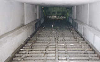
Figure 3.8.1. Grate clinker coolers.
At the discharge end of the kiln, the clinker is red hot and contains around 1.0 million Btu per short ton thermal energy. The clinker is also to some extent still reacting chemically toward creation of various clinker minerals. The purpose of the clinker cooling is to recoup some of the heat in the clinker, thereby making it cool enough to handle. We also want to stop the chemical reactions in the clinker at the point most favorable to the cement quality.
TYPES OF CLINKER COOLERS
What governs the design and selection of a clinker cooler? Surely, today, any design project would include some of the following requirements: low capital cost; optimum cooling rate for good clinker quality; low clinker discharge temperature; least possible impact upon the environment; high heat recovery; low power consumption; low wear and maintenance cost, and reliable to oper-ate, causing minimal downtime; and easy to control so it delivers a steady flow of combustion air at an unvarying temperature to the kiln and calciner. These criteria are of immediate interest to a manufacturer of cement who buys a cooler for clinker. The designer of the clinker cooler looks at these criteria and tries to optimize the design, depending upon the weight of each of these individ-ual criteria.
Over the years, the criteria that are used to select coolers have changed. The technology of clinker cooling has developed as well, so that many different types of clinker coolers have been applied since the infancy of the portland cement manufacturing industry in the late l9th century. The following sections will describe the most common clinker coolers with particular emphasis on the reciprocating grate cooler.
Planetary Coolers
The name of the planetary cooler is derived from the fact that it circles the kiln like planets circle the sun. A planetary cooler consists of a number of cooling tubes mounted around the circumference of the kiln shell (Figure 3.8.2).
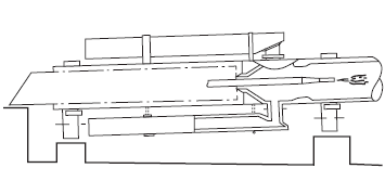
Figure 3.8.2. Planetary cooler.
The advantage of the planetary cooler is its simplicity: it requires no excess air to handle, no fans or motors, and no instruments. It is self-adjusting. The power consumption is only about 0.5 to 1 kilowatt-hours per ton of clinker added to the kiln drive and exhaust fan, making it the lowest for any kind of clinker cooler. The heat losses through radiation and sensible heat in clinker are between 0.40 and 0.45 mega-joules per kilogram of clinker for an economical dry-process kiln even and lower for wet-process kilns. Planetary coolers have been used successfully for kilns as big as 4000 metric tons per day, though not in North America.
These coolers were popular in the 1960s and 1970s when many dry process 4-stage preheater kiln systems were built around the world. In North America, most of the dry process kilns were supplied with grate coolers.
The planetary cooler does not allow withdrawal of tertiary air for a calciner. As most kiln systems built today have calciners, the planetary cooler is becoming a relic of the past. One weakness of the planetary coolers is that they can be costly to maintain. The cooler inlets often wear out too fast due to the thermal, mechanical, and abrasive stress to which they are subjected. To decrease the resulting maintenance and downtime, over the years there has been continuing improvement by trials with inlets made of high temperature metal alloys or ceramic materials.
Rotary Coolers
Some of the earlier coolers were almost like another kiln following the clinker burning tube or, using another picture, take the planetary coolers, combine them into one tube with its own support and drive, and you have a rotary cooler (Figure 3.8.3).
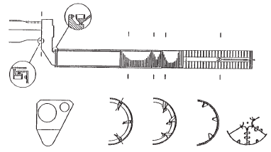
Figure 3.8.3. Rotary cooler.
The modern rotary cooler is equipped with ceramic lining and lifters based upon the development of the planetary cooler. Special seals at the kiln outlet and the cooler inlet are required. To avoid spillage from the inlet, the cooler is inclined 2.5° and given a speed of rotation of 3 rpm. The power consumption for the drive is about 3.5 kWh/ton. The clinker temperature is 200°C to 250°C, but is reduced to about 150°C by water injection in the outlet. Presently, no cooler of this type is used in North America.
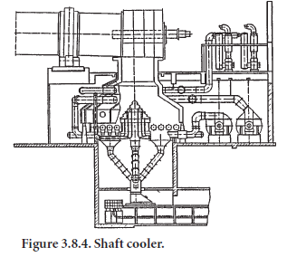
Shaft Coolers
As a curiosity, we should mention the shaft cooler (Figure 3.8.4), which has been operating with a 3000 metric ton per day kiln in Europe since 1976, but apparently has not gained a foothold in the cement industry. The cooler requires fairly even clinker size distribution. The upper part is operated as a fluid bed in order to avoid agglomeration and to ensure even distribution. The power consumption is high, 10 to 12 kWh/ton, because the cooling air has to be compressed to about 20 kPa. With minimum air to the cooler, the clinker temperature is 300 °C – 350°C, but it is reduced by water injection in the lower part.
It should be added that shaft coolers of somewhat different design, such as the Niems cooler, have been used very successfully for modern lime burning kilns. Burnt lime has a rather uniform grain size distribution and therefore is much easier to cool in a shaft cooler than cement clinker.
Traveling Grate Coolers
It should be mentioned that travelling grate coolers have been used in the past; but, generally, they were never developed to the same high standard of operational reliability as the reciprocating grate cooler. Travelling grate coolers have been used mostly in connection with grate preheater kilns, which produce a very uniform clinker size. The travelling grate cooler has the disadvantage that the clinker is conveyed as a solid bed. To obtain effective clinker and air distribution, it is often neces-sary to use pulsating air.
Grate Coolers
The grate cooler is by far the most common clinker cooler in North America. Where the air and clinker move in opposite directions (also called counter current) in the planetary, rotary, and shaft coolers, the grate cooler is based on the cooling air moving cross current to the direction of the clinker movement. This type of cooler can produce clinker discharge temperatures around 80°C; but it needs more air for cooling than can be used in the kiln, and the excess air has to be removed and dedusted. The amount of air needed varies according to the clinker size distribution and to the clinker temperature required. It is costly to cool to low temperatures. The amount generally lies between 2.3 and 3.3 kg of air per kilogram of clinker; but in order to cope with forced conditions and fluctuations, the cooling fan capacity is normally designed to allow the introduction of 4.5 kg of air per kilogram of clinker. The specific load on grate coolers built since the mid-1970’s is often 35 to 45 metric ton per day per square meter grate area compared to 20 for grate coolers built in earlier times. This is the result of the tendency to improve heat recuperation by working with a thicker clinker bed on the grate.
The cooler consists of one or several grate sections. The sections are defined by their location or their function, or by whether they are connected to a certain drive (for instance, ‘inlet grate,’ ‘2nd movable grate,’ etc.). Each grate consists of a certain number of rows of plates. The plates have been the subject of much development in the 1990s, as will be described later. The air to the grates is supplied in various ways: through air blown into compartments under the grates or blown into ducts (often called ‘airbeams’) connected directly to a limited number of grates.
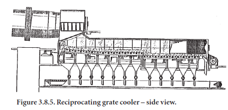
A typical cooler built between 1970 and 1990 works in the following fashion. From the kiln, the clinker drops onto a stationary air-quenching grate. This grate may be horizontal or inclined. It consists of one or several rows of plates. In the cooler shown in Figure 3.8.5, there are three movable grates; the first is with an inclination of a few degrees, and the other two are horizontal. Below the grate, the cooler is divided into a number of compartments, each provided with fans equipped with adjustable guide vanes for automatic air flow control and minimum power consumption. Clinker spillage through the grate is collected in hoppers and removed through airtight flap valves to the clinker conveyor. Since the 1990s, the underside of the plates in the quench grate and the first grate have been connected directly to cooling fans. This has allowed better individual adjustment of air to different parts of the grate.
The efficient sealing between the compartments permits operation at high and different pressures in the various compartments. With a normal clinker bed thickness of 600 mm, the pressure drop at a constant air flow per unit area will decrease from about 5.9 kPa in the hot end to about 2.0 kPa in the cold end. The fans are sized accordingly so that the maximum pressure decreases from 7.3 kPa to 2.9 kPa. For trouble-free operation, it is an advantage to use more air per grate or unit area in the hot end, up to 200 kg/min/m2, and less in the cold part, say 40 kg/min/m2.
The width of the grate is reduced in the inlet in order to spread the clinker more evenly. Together with the high air flow and the thick layer of clinker, this helps to provide a uniform clinker bed thickness, which in turn gives a uniform air flow over the width of the grate. This is essential not only to avoid local overheating of the grate, but also to avoid “snowmen” – the clinker is kept moving throughout the whole grate until the individual particles have lost their stickiness and ability to cling together.
The clinker is pushed through the cooler by the reciprocating movement of rows of plates. Usually, every second row of plates in a grate is movable. The other rows are stationary.
A crank arm moves the movable frame on older coolers. The rows of plates are moved by a connecting rod which is centrally fixed to the movable frame, so that twisting is avoided. The rod goes through the wall via an airtight seal and is driven by a direct current motor or by a hydraulic piston. In the 1980s one supplier started to offer a pendulum suspended frame, such as shown in Figure 3.8.6. This method of moving the frame is claimed to be particularly effective at keeping tight tolerances of movement to minimize wear on side castings. The activation by a single hydraulic cylinder with an asymmetric stroke (slow forward, fast back), helps minimize mixing of the clinker and, thereby, bed resistance to airflow. The speed of frames, whatever way they are moved, can be varied between 3 and 30 strokes/min. In normal operation, 5 strokes/min is adequate, providing ample spare capacity.
Figure 3.8.6. Grate cooler – pendulum frame for moving grate plates.
Before the 1990s, all grate plates, both the movable and stationary, were of identical design. They were cast with circular holes – in the front part of the cooler they were made of heat-resistant steel; in the cold part, of cast steel. The shoes of the plates were bolted to a cross beam away from the heat. All designs allow removal from underneath where there is easy access to the grate through the undergrate compartments.
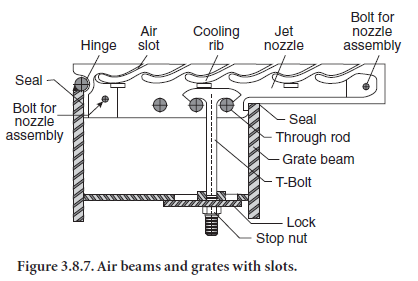
In the late 1980s a new type of grate plate connected to an airbeam was introduced. This plate contains inclined and curved slots rather than holes (Figure 3.8.7). The slots are shaped by small blades that are easily replaced from the top of the plate. This innovation was so effective that by the 1990s all major suppliers were offering grate plate with slots instead of holes for the hot part of the cooler. The suppliers’ plate designs varied, but they all contained a pocket where cooled clinker could rest and minimize metal wear, and they were all connected directly via an airbeam to a fan rather than being supplied with air through an undergrate compartment. These changes resulted in better protection of the grate from thermal and abrasive stress caused by hot moving/sliding clinker and improved cooling of the clinker by better control of air flows.
The clinker discharges from the cooler across a grizzly to a hammer mill or hydraulic roll crusher located in the cooler outlet. The crusher may be installed in the middle of the cooler, before the last grate, to break up lumps and large clinker, and to ensure their efficient cooling. The thermal stress on the crusher is obviously greater in the middle than at the end of the cooler.
When a cooler is operating with a thick clinker bed and evenly distributed clinker and air, and is designed with sufficient retention time of clinker in the cold end, hot lumps do not cause severe problems.
Grate Coolers Without Excess Air Vent Stack
The excess air from the grate cooler normally has to be dedusted and exhausted through a stack. This is costly and may be difficult to get permission for from licensing authorities. To avoid these problems, some plants have installed a combination of a short grate cooler and a gravity or “G-cooler” or they have installed recirculation of the excess air.
The gravity cooler (Figure 3.8.8) is used in connection with a short grate cooler, furnished with just the amount of air needed for combustion in the kiln and calciner. The clinker discharged from the grate at a temperature of about 500°C is crushed and carried to the top of the gravity cooler, through which it drops slowly at 2 – 3 cm/min, while cooled indirectly by ambient air blown through cooling tubes. After about two hours of slow downward travel, the clinker is discharged at a temperature of about 100°C. The power consumption for the fans of the G-cooler is around 1 to 2 kWh/ton. Control of hood pressure and the conveying of occasionally very hot clinker between grate and gravity cooler requires special attention to make this system operate well.
Another way to avoid dedusting the excess air from a grate cooler is to cool the air in a heat exchanger and then recirculate it to the grate (Figure 3.8.9). The heat exchanger is designed so that ambient air is blown on the outside of the cooling tubes through which the excess air from the cooler is drawn.
Cross-Bar™ Cooler
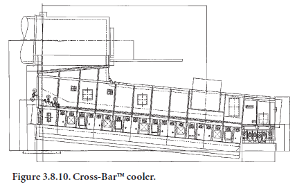
In the late 1990s, a new type of clinker cooler was introduced. It shares the horizontal conveying of clinker through which a vertically moving mass of cooling air is blown with the reciprocating clinker cooler, but has several innovative and unique features. The most striking is that clinker are no longer conveyed by rows of grate plates moving back and forth, but by wedge-shaped bars suspended above the grates, which are all stationary (Figure 3.8.10). These bars move back and forth and have inspired the name “Cross-Bar™ Cooler.”
Since the plates no longer move, they have been made larger. The traditional size of a cooler grate is 30×30 cm; the cross bar cooler plates are 1×1 m. Furthermore, each plate is supplied with an amount of air that is individually and dynamically adjusted to fit the cooling needs of the moment. This is accomplished by a mechanical flow regulator valve located in the air supply channel affixed underneath the grate plate. This regulator passes air from the undergrate chamber to the holes in the plate as shown in Figure 3.8.11. This eliminates the need for airbeams between cooler fans and grate plates, and the mechanical problems associ- Non-uniform clinkerated with them. Currently,
there are only a few crossbar coolers in cemen toperation. The vendor claims the cooler is consid-erably more efficient at heat recuperation than ordinary reciprocating grate cooler As. The amount of cooling air is reduced from 2.8 to 1.9 kg air per kilogram clinker, resulting
in a low power consumption of 4.0 kWh/ton of clinker cooled.
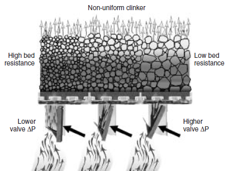
Figure 3.8.11. Mechanical air flow regulator.
COMPARISON OF DIFFERENT COOLER TYPES
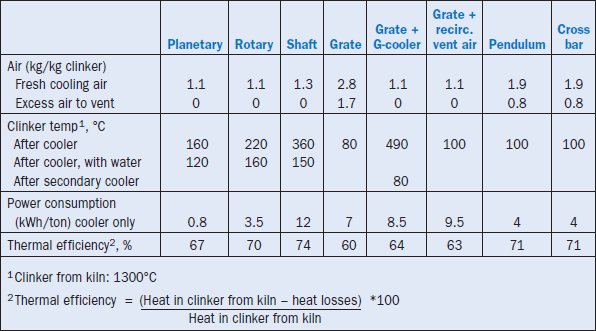
A study made in 1980 of the investment costs for grate coolers with different types of dust collectors and grate coolers operating without excess air led to the surprising result that the total installed equipment costs are the same within ±5%. The decisive factors for choosing between these clinker cooling solutions are therefore their operational costs and reliability. Typical opera-tional data for the different cooler types are tabulated in Table 3.8.1.
Table 3.8.1. Typical Operational Data for Different Cooler Used in Dry Process Kilns
OPERATION OF GRATE CLINKER COOLERS
Mass and Heat Balances
In the previous chapters we have mentioned the varying amounts of secondary air and tempera-tures found in different types of clinker cooler systems. To better understand these differences, we might ask how much of the heat contained in the clinker dropping into the cooler has been recu-perated to the air returned from the cooler to the kiln system?
Some of the heat entering the cooler will be lost in the cooled clinker, radiation, and possibly the vent air. The amount recuperated is a measure of the thermal efficiency of the cooler. The more recuperated, the more thermally-efficient it is.
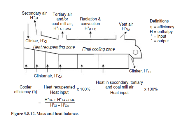
To calculate the thermal efficiency, it is necessary to establish mass flows, temperatures, and heat flows. Figure 3.8.12 shows a typical clinker cooler with its heat inputs and outputs. The thermal effi-ciency of the cooler is defined as the relationship between the heat recuperated and total heat input as shown in the equation in the figure. The lower the heat losses in clinker, vent air, radiation, and convection, the higher the amount of heat recuperated in secondary air and the higher the thermal efficiency.
Heat flow is a function of mass and temperature. The higher the mass and temperature of second-ary air, the more heat is recuperated. The air used for combustion in the kiln and calciner, plus the air excess creating the oxygen we measure in the kiln system, comes from the primary air supplied through the burner(s), and the secondary and possibly tertiary air drawn from the cooler. For a given combustion air need, to get the amount of secondary air and thus the cooler thermal effi-ciency to increase, the quantity of primary air and/or infiltration air must be decreased. It is important to maximize the amount of secondary air by minimizing primary and air infiltration rates and to maximize the secondary air temperature by minimizing cooler heat losses.
Since the amount of combustion air depends on the overall fuel consumption, it becomes clear that the type of kiln system influences the thermal cooler efficiency considerably.
A modern-type preheater kiln, consuming 3.0 million Btu per short ton clinker, should be oper-ated at a thermal efficiency between 64% and 68%,ifwell adjusted. A long dry kiln, consuming 4.0 million Btu per short ton, should run between 68% and 72%; and a wet-type kiln, consuming 5.0 million Btu per short ton, between 70% and 75%. Nevertheless, many clinker coolers are oper-ated at considerably lower thermal efficiencies. It is evident that operating a clinker cooler at peak thermal efficiency improves overall heat consumption considerably.
For any given grate cooler, one can usually measure the amount of cooling air blown into it, as well as the amount of vent air and coal mill air exhausted. The amount of secondary air is calculated by difference or, perhaps, from the amount of coal, backend oxygen, and primary air used. Typical mass balances are shown in Table 3.8.2.
Table 3.8.2. Air Mass Balance for Grate Cooler
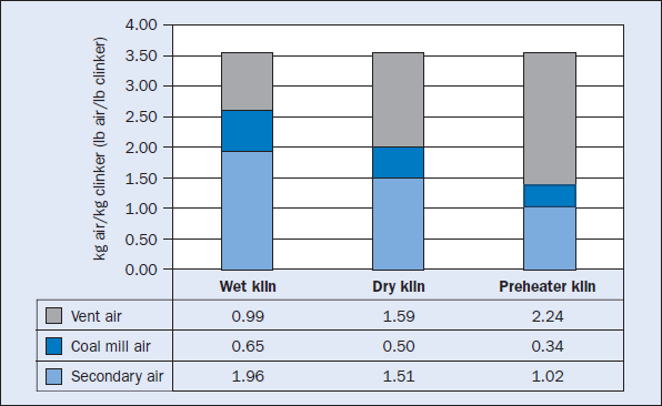
Table 3.8.3. Heat Balance for Grate Cooler
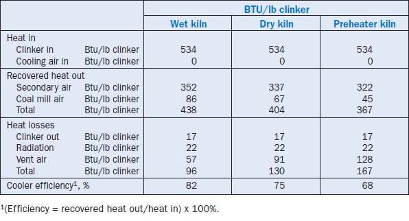
Once the temperatures of the various material streams, their specific heat capacity, and the radia-tion losses have been determined, one can calculate a heat balance, such as the one shown in Table 3.8.3.
When the balance is established, the cooler heat recuperation efficiency can be calculated as follows:
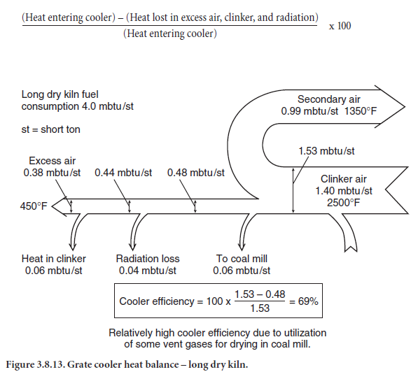
An example is given in Figure 3.8.13. As mentioned earlier, a modern clinker cooler should have an efficiency of 64% or better no matter what kiln it serves. This means that it should be able to move about two-thirds of the heat from the clinker exiting the kiln to the combustion air entering the kiln system.
Automatic Control of Grate Coolers
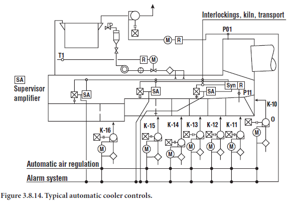
Three groups of machine adjustments are usually automated to obtain: 1) constant air flow through the clinker bed in terms of mass of air per unit area and per mass of clinker, and 2) constant, slightly negative pressure (suction) in the kiln hood. An example is shown schemati-cally in Figure 3.8.14.
The primary objective of a clinker cooler control system is to stabilize the cooler operation and thereby provide a more uniform flow of heated air for combustion in the kiln and possibly the calciner. The secondary objective is to provide a controlled response during kiln upsets so that the upsets have a minimum impact on the primary objective.
Single and cascade analog controllers, or digital equivalents of these controllers, are the most common ones in use. Ideally, the grate cooler is controlled by one algorithm which optimizes the cooler opera-tion during normal operation while a second control algorithm steps in during upset kiln conditions to ensure that the cooler is not damaged by high temperatures or mechanical problems.
The pressure in the undergrate compartments and air beams (if present), the flow of air into or out of fans, and the speed of the movable grate frame are all controlled by PID loops. Other parameters are monitored simply to ensure they are within a desired operating range. These include fan motor current, kiln speed, motor running status, excess air, and grate plate temperatures.
Using undergrate pressure to control grate speed is acceptable if cooler conditions remain near ideal. To avoid problems associated with erratic first and second compartment pressure, both first and second compartment pressures can be measured for determining a weighted average under-grate pressure. This smoothes out the undergrate pressure and often lets the cooler run steadier.
The finer the clinker, the harder it is to blow air through the bed. With the control loop in auto-matic mode, a decrease in clinker size will result in an increase in undergrate pressure, until the control loop has sped up the grate, causing a lowering of the clinker bed depth. Conversely, very large clinker will result in unusually low undergrate pressure which will decrease cooler speed and result in excess bed depth, and may even overload the drive. The cooler control system should include elements that detect and correct these conditions.
In the case of a two- or three-drive cooler, the second drive should be controlled by the undergrate pressure of its first compartment. When the second drive’s first compartment is too large for its pressure to be successfully used in connection with speed control, the second drive has to follow the first drive. In that case, the first drive’s speed multiplied by a factor represents the second drive speed. The second drive’s speed should always be higher than the first drive’s speed to avoid clinker piling up between the two drives.
Occasional high grate plate temperatures in the first and second compartments can represent an obstacle to optimizing cooler compartment airflow distribution. During upset conditions where high grate plate temperatures occur, one may have to increase the cooler movable grate frame speed for safety reasons. The grate plate temperature is then permitted to manipulate the under-grate pressure setpoint. As grate plate temperature increases, it will decrease the undergrate pres-sure setpoint which speeds up the cooler movable grate frame drive.
In one particular case, this safety interlocking resulted in no grate plate failures for two years where, in the past, grate plate failures had been an ongoing problem.
In some cooler systems, high vent air temperatures will result in automatic opening of a tempering damper in the vent airduct to protect downstream equipment from overheating. The vent air volume increase caused by the opening of this damper or even just by the high vent temperature may make the total volume exceed the capacity of the vent fan. If this is a constraint, it may be prudent to automatically reduce undergrate compartment airflows in the latter part of the cooler to restore kiln hood draft control when the vent air temperature (measured before the introduc-tion of tempering air) exceeds a certain threshold valve.
In applications where vent fan capacity and high clinker discharge temperatures are a problem, the kiln hood’s draft can be controlled as well by the last compartment fan. By doing this, it is possible to increase the amount of cooling air and to lower the clinker discharge temperature during normal operation. In this mode of control, the vent fan is run on fixed speed close to maximum capacity. During upset conditions, the amount of cooling air is reduced, resulting in a higher clinker temper-ature, which would have happened anyway. In a few coolers with limited venting capacities, this control approach has led to considerably lower overall clinker discharge temperatures.
Finally, in order to minimize the need for control room operator involvement, other attractive control features to strive for include automatic initialization of dampers to the full closed position on fan startup, automatic reduction in airflow on fan achievement of maximum motor current, and automatic airflow increases programmed for kiln startup.
OPTIMIZATION OF GRATE COOLER OPERATION
A smooth cooler operation depends upon many factors. In the preceding paragraphs several of the important design features that affect the operation, such as burner pipe location, cooler width, and control loops, have been mentioned. In the following section, these points have been revisited, while also dwelling on the fact that optimization of a clinker cooler can be divided into three tasks: 1) maximizing the amount of secondary air, 2) maximizing the secondary air temperature, and 3) maximizing the uniformity of the operation.
Burner Pipe Position
The first step in optimizing a cooler operation begins in the kiln. The burner position has a crucial influ-ence upon the kiln and cooler performance. Long wet and dry kilns with a fuel consumption of more than 4.0 million Btu per short ton of clinker, which were common in the past, needed high amounts of combustion air. Low secondary air temperatures ensured a fast clinker cooling inside the kiln, and the overall thermal efficiency of the cooler was acceptable. Today’s low-fuel-consuming kiln systems have low combustion air requirements, thus giving high secondary air temperatures and slower clinker cooling.
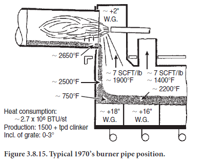
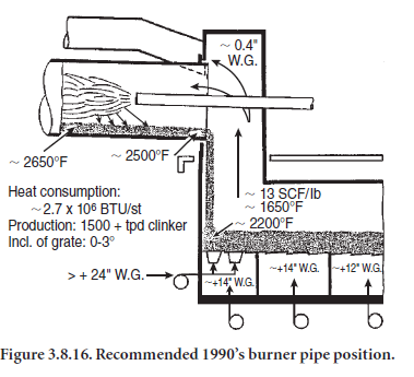
Figures 3.8.15 and 3.8.16 show the difference between two burner pipe positions. Positioning the burner tip at the kiln nose or even into the kiln hood (Figure 3.8.15) means that the flame ignition takes place close to the kiln’s discharge, thus keeping the clinker hot until they drop into the cooler. This can have several undesirable consequences as follows:
• The clinker discharged onto the clinker bed can form large clinker agglomerations, leading to poor cooling rates because only the clinker closest to the grates are rapidly cooled.
• High temperature clinker reaches the discharge end of the cooler, resulting in elevated clinker discharge and vent air temperatures. The overall cooler thermal efficiency decreases and fuel consumption increases.
• High secondary air and kiln clinker discharge temperatures can result in a severe “snowman” formation, especially if coals with high ash content are used. In addition to all these disadvan-tages, operational and maintenance problems are likely to occur.
In contrast, positioning the burner tip approximately 1 to 2 m into the kiln (Figure 3.8.16) improves the kiln’s own heat recuperating and cooling zone.
The pre-cooled clinker drops at a lower temperature into the cooler and the secondary air temper-ature drops. The requirement to cool the clinker quickly is fulfilled. The clinker reaches the latter clinker cooler zones at a lower temperature, which results in lower clinker discharge and vent temperatures. Less required cooling air relieves the vent air system and saves considerable electrical energy. The overall cooler thermal efficiency improves. In addition, the cooler now runs at a higher availability and lower maintenance cost. The formation of “snowmen” is unlikely.
There may be one drawback in pushing the burner into the kiln – it might represent a problem in regard to burner refractory life. Good results were experienced with extreme high strength low-cement type refractories on burner pipes in very severe applications.
Maximizing the Amount of Secondary Air
Low primary air and low air infiltration rates at the kiln discharge maximize the amount of secondary air. Low primary air rates can only be accomplished with semi-direct and indirect firing systems that offer primary air rates as low as 6%. Low air infiltration rates at the kiln discharge can be accomplished with good hood sealing and an effective kiln discharge seal.
Many plants now employ an effective leaf-type kiln discharge seal where overlapping sheets of high quality steel ride on the kiln cowling. This arrangement exhibits little tendency for clinker to pry open the seal. A puffing kiln hood does not open a gap between leaves and the air cowl. This seal has proven itself in many applications. Repairs are easy and overall costs are low.
If the kiln system has a calciner, it is important that as much of the air as possible used for combustion comes from the clinker cooler. Thus any potential opening to ambient air between the calciner and the cooler should be kept as tight as possible. Such openings could be inspection doors, material discharge flaps and damper housings on tertiary air ducts, and kiln material inlet seal and kiln riser poke holes if an in-line calciner is used.
Maximizing Secondary Air Temperature
Maximizing the secondary air temperature means getting the best heat transfer between clinker and cooling air. The heat transfer is optimized by 1) optimization of clinker bed distribution, and 2) optimization of the cooling air distribution.
A clinker cooler basically is a heat exchanger. In contrast to most heat exchangers, both mediums –clinker and air, come in direct contact with each other. Therefore, the effectiveness of heat exchange largely depends upon the surface with which both mediums come into contact. In a clinker cooler, the more uniform the clinker size distribution and the clinker granulometry, the more effective the heat transfer.
While the clinker size, for the most part, cannot be altered, the overall heat transfer can be opti-mized with a good, uniform clinker bed distribution.
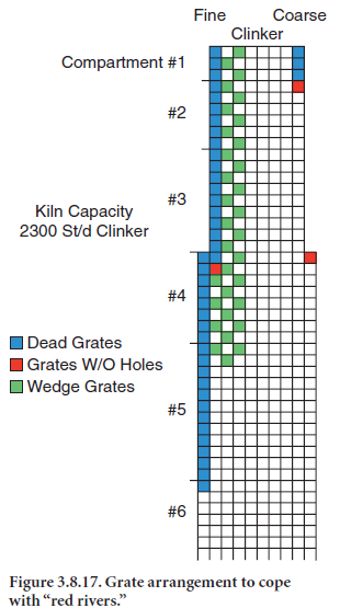
The fact that especially large diameter type kilns tend to discharge fine clinker on the kiln’s load side and coarse clinker on the opposite side can make it difficult to get good clinker distribution. Due to the high air resistance of a fine clinker bed, “red rivers” often are inevitable. Studies show that “red rivers” can cause a variation in air distribution of 1:6 between the fine and coarse clinker side and can even cause clogging of the bed. This is why grate plates sometimes become red hot in places. “Red rivers” also cause an increase in clinker discharge temperature.
Measures for improving the clinker distribu-tion should start at the cooler inlet. Where “snowmen” cause poor clinker distribution, the cooler back and sidewalls can be kept clean with the help of compressed air cannons. Some improvements are possible by slowing down the movement of the fine clinker bed and diverting more fine clinker to the coarse cooler side, thus increasing the overall clinker bed resistance which pushes more air through the fine clinker bed. This diversion can be done by using wedge-type grates with 125-mm or 200-mm high faces. The grates are arranged in a checkerboard pattern as shown in Figure 3.8.17.
An often successful way to improve the situation is to narrow the cooler grate area on the fine clinker side. By doing so, the clinker bed becomes narrower and often eliminates a severe segrega-tion of fine and coarse clinker. It is recommended that the cooler inlet grate width not exceed 2.5 m for kiln capacities up to 2,500 metric tons per day of clinker.
Figure 3.8.17 shows that some air holes in corner grates are blanked off. Corner areas often have a low clinker load which results in heavy air channeling and bypassing the clinker load. Blanked off air holes ensure that cooling air is diverted into the clinker load.
When severe “red river” conditions exist and loss of cooler grates are experienced, “Ondufin” grates can be applied. The grates have cooling fins on the underside which increase the cooling surface. The grates stay cooler and last longer. In addition, if a grate is burned through, the fins prevent large clinker spillages for a considerable time.
When “red river” conditions in a pre-1990’s style cooler are extremely severe, compartments can be divided into two sections. Two cooling fans, one on each cooler side, assure that both grate areas, the fine and the coarse side, receive the proper amount of air. Or, the design can be upgraded to one with airbeams or mechanical air flow regulators for small groups of grates.
Some suppliers, borrowing from the airbeam technology, offer a grate plate design for pre-1990’s coolers where the air has to travel through a labyrinth in the grate – first up, then down – before exiting into the clinker bed. This provides an effective clinker seal that reduces the amount of clinker falling through the grate plates to the undergrate compartment.
Increasing the clinker bed thickness generally improves the overall clinker distribution and heat transfer. Good results have been experienced with clinker beds up to 1 meter deep. In addition, lower grate speed has had a positive effect upon grate wear rates.
High undergrate pressures and airflows adversely affect the conveying action of a reciprocating grate. High air pressures can reduce the friction between the clinker and the grate, which in turn can speed up the movement of the clinker toward the cooler discharge. The air, which expands as it rises in the bed, causes the clinker at the surface to be fluidized. The result might be that clinker flows down the slope if the grate area is inclined or that the clinker can only be moved with extremely high reciprocating speed on horizontal type coolers. To prevent clinker from flowing forward, the single grate surface should be at least horizontal.
Experience has shown that the best results can be attained with a maximum of 4.7 to 5.5 kPa undergrate pressures in horizontal and 3 degree inclined coolers, and 2.0 to 2.5 kPa in old 10 degree inclined coolers.
AIR DISTRIBUTION VERSUS OVERALL COOLER EFFICIENCY
Optimized air distribution also improves the overall thermal cooler efficiency and prevents damage to grates due to overheating. To achieve this goal, predefined amounts of cooling air need to be established for every cooler compartment. Coolers with airbeams or mechanical air flow regulators can refine the air distribution even more to sections of grate plates or to individual plates.
The optimization of airflow is especially important for the heat recuperating zone. Too high amounts of air do not give maximum secondary air temperature. Too low amounts of air elevate the clinker discharge temperature. Too high amounts of air also promote fluidization of the clinker. As the finer clinker particles are likely to be entrained in the locally intensified air flow, high amounts of dust cycles between kiln and cooler are likely. Dust particles might also be picked up from highly fluidized areas and concentrate in others, thereby intensifying any “red rivers.”
Extremely high airflows also promote heavy air channeling, giving a poor heat exchange for a grate cooler of 1970’s to mid-1990’s vintage. It is recommended that maximum airflow not exceed approx-imately 140 normal cubic meters per minute per square meter of cooler grate area. Figure 3.8.18 shows a chart of optimized cooling air distribution for a typical eight-compartment reciprocating grate cooler. The first five compartments (including quench compartment) supply secondary air and tertiary air if applicable; compartments #5 through #8 cool the clinker to a final temperature of approximately 100°C. Lowering the clinker discharge temperature further with more air increases the electrical power consumption considerably. Depending upon the total amount of cooling air used, the power consumption for the cooling fans can run between 3 and 8 kWh/ton of clinker, plus up to 4 kilowatt-hours for venting.
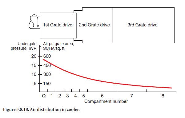
As can be seen, the maximum specific amount of air per unit of grate area goes into the quench compartment and compartment #1 to quench the clinker and assure low grate temperatures. The specific airflows per unit of cooler area gradually decrease toward the cold end of the cooler.
Some older coolers still have one cooling fan for up to three compartments. The distribution of air into each compartment is difficult since the cooling air will try to migrate into the compartment with the lowest undergrate pressure. This is especially true when heavy loads travel down the cooler. Employing one air fan for each compartment and making sure they are well air-sealed from each other will result in a lower overall clinker discharge temperature and less air usage.
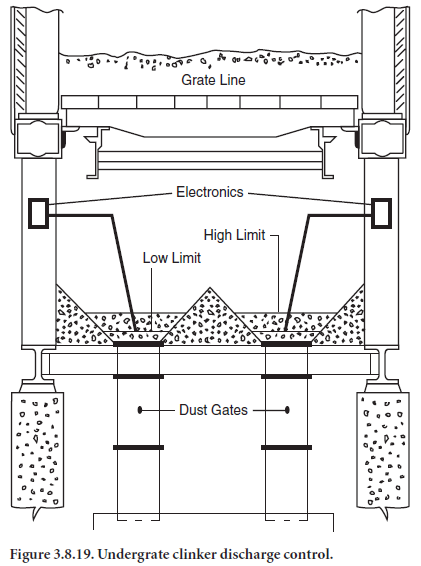
In order to allow deep clinker beds and defined airflows in each compartment, one needs good undergrate compartment sealing, especially where drag chains pass through compartments. Where drag chains are located below the cooler, the best sealing is accomplished with flap valves con-trolled by level indicators located in the undergrate compartment. The flap valves are only oper-ated if material inside the compartment reaches a certain level. Figure 3.8.19 shows this arrangement.
Efforts to avoid the mixture of low and high temperature cooler air above the clinker bed are important as well. If considerable amounts of air from the back-end compart-ments mix with air from the heat recuperating zone, the secondary air temperature drops while the vent air temperature increases. We can take some steps to avoid secondary (and tertiary) air from mixing with the vent air. At the point in the cooler where these two air streams split off in different direc-tions, an arched brick wall or some hanging stainless steel dampers can be installed. From this part of the cooler, the cooler roof should be sloped at approximately 15°as it approaches the cooler throat and 5° to 10° as it approaches the vent air take off. The sloped roof changes the bullnose from 90° to approximately 75°. The resulting lower velocity in the lower part of the cooler throat reduces the amount of fine particles returned to the kiln.
Wherever possible, the cooler throat velocity should be held below 7 m/sec. New systems should even be designed with velocities as low as 3.5 m/sec.
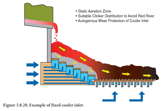
A proper and uniform distribution of the clinker upon the grate is of importance, as already mentioned. Ideally, you would like a giant stirrer to mix the large and small clinker (that are segre-gated as they fall into the cooler) together again, and then have them spread out in an even layer upon the grate. Equipment that has been used for this purpose includes: 1) sloped inlet, 2) water-cooled adjustable steel impact inlet plate, 3) reducing effective grate width (horseshoe pattern of inlet grate plates), 4) stationary quench grates at the front of the cooler, and 5) spreader beam across the cooler. In the 1990s another interesting method was introduced. It consists of aeration of a slop-ing bed at the inlet end of the grate. This area is provided with a series of fixed windboxes arranged stepwise and equipped with cast metal grate elements designed so that no particles can fall through them (Figure 3.8.20), that is, with the airbeam and pocket grate technology mentioned earlier.
A considerable pile is built up over the grate plates, which contain pulsating air. The air expands the pile and in particular moves and mixes the finer clinker with the coarser. At the same time making the upper portion of the pile slide gently into the cooler while it is being spread out.
Final Words
Clinker coolers are an integral part of the kiln system. Select them carefully, keep working at opti-mizing them, and overall plant performance is bound to improve!
REFERENCES
Gagnon, Denis, “Upgrading a Clinker Cooler,” Proceedings 38th IEEE/PCA Cement Industry Technical Conference, Los Angeles, April 1996, pages 156-170.
Herchenbach, Horst, “Cement Cooling – The Key To An Economic Kiln Operation and Good Clinker Quality,” Proceedings 21st International Cement Seminar, Rock Products, Chicago, Illinois, 1985, pages 41-54.
Keefe, Brian P., and Christensen, Kim Pandrup, “The Cross-Bar Cooler: Innovative and Proven,” Proceedings 42nd IEEE-IAS/PCA Cement Industry Technical Conference, Salt lake City, Utah, May 2000, pages 135-147.
Klotz, Bryan, “Design Features of the Polysius Clinker Cooler,” Proceedings 42nd IEEE-IAS/PCA Cement Industry Technical Conference, Salt lake City, Utah, May 2000, pages 159-170.
Labahn/Kohlhaas, Cement Engineers Handbook, 4th Edition, Bauverlag GmbH, Wiesbaden and Berlin, 796 pages, 1983.
Lecture 55, “Cooling of Clinker,” F. L. Smidth’s Cement Production Seminar, 1981.
Nobis, Rainer, “Evaluation and Optimization of Clinker Cooler Operations,” Proceedings 25th International Cement Seminar, Rock Products, Chicago, Illinois, 1989 pages 119-140.
von Wedel, Justus, “The IKN Pendulum Cooler,” Proceedings 42nd IEEE-IAS/PCA Cement Industry Technical Conference, Salt lake City, Utah, May 2000, pages 149-157.
Technical package and business support CEMENTEQUIPMENT.ORG offers a professional technical package built for engineers, plant teams, buyers, and decision-makers. The reference value is positioned at more than $50,000, while the package is offered at about $249. If you are researching this topic for a live plant problem, project, or supplier discussion, use the package for depth or request direct commercial support.Need organized cement references instead of searching article by article?
Pingback: Top Industrial Uses of Metal Grating and Grate Bars in High-Temperature Environments? - Custom Metal Parts Manufacturing | Precision Stamping, Welding, Casting, CNC Machining - Prime Custom Parts