Contents
Everything you need to know about clinker/cement Grinding
if You read and understand this article , you will be ready to be a cement grinding area manager.
FEED AND FEED SYSTEM
Feed Temperature
Plants with satellite coolers have high clinker temperatures: e.g. Cumarebo, Oujda…..
Exit satellite cooler 200-250°C.
Exit grate cooler 100-150°C.
HGRS standard for a grate cooler is that clinker temperature should be 80°C above ambient temperature. Reality is that it is a little bit igher (90°C-100°C).
Karl-Heinz has never measured more than 150°C clinker temperature at mill inlet. Depends on storage time and whether stored inside / outside. Solution to satellite cooling is to pour water onto satellites (Karl-Heinz saw this in Korea).
Example Chekka, clinker temperature > 150°C with coal, but then lower with petcoke (clinker made from petcoke is finer à better heat exchange in cooler)
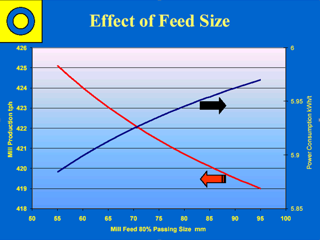
Feed size
Clinker density 1.4 (Dotternhausen).
Ball Mill
- Cement Lafarge max R5% >25mm, Holcim <50mm. Standard offer from mill manufacturer is R5% >30mm
- Raw Meal max R1% > 30 mm (Lafarge). Holcim “<25 – 50mm”.
- For quartz, feed must be precrushed to <10mm. Note that 90mm are required to crush quartz fed at <3mm. Quartz demands a high crushing energy AND a high grinding energy.
Coarse and Fine Clinker
It is “accepted” that coarse clinker is in many cases easier to grind than fine clinker. Yet, when clinker from the same kiln system is screened into coarse and fine fractions, lab testing is unable to determine significant differences in terms of energy requirements at high fineness (see also clinker grindability). On the other hand, some plants can tell when their clinker breaker has worn out. The oversized clinker causes the mill to choke and lose production.
In general, a mill system is set up to accept clinker of a certain size (or PSD) and if it receives anything different, then production rates are usually affected.
Clinker Size Segregation
Clinker segregation is another well known situation which is a result of poor stockpiling practices (end piles especially) and poor bin design and bin filling practices. If segregation is occurring, the mill feed can swing from coarse to fine and back again. When the mill is receiving clinker that’s too coarse, retention in the first compartment rises (and sometimes backspills) and the second empties and starts to over grind. If the clinker becomes too fine then it flushes through immediately to the second compartment and overwhelms it. Mill outlet fineness suddenly drops and the circulating load jumps up rapidly.Some spectacular mill cycles have resulted from clinker segregation problems.
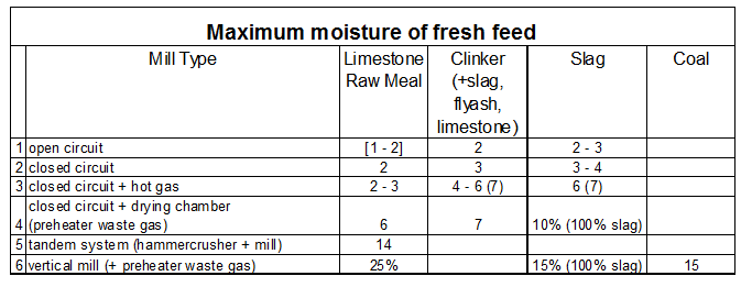
Feed Moisture
Ball Mill
Feed Chemistry
Limestone specific weight = 2.7 g/cm3
SO3 Effects
The clinker SO3 content has been recognized as having an impact on grindability. Higher SO3 in clinker results in a reduction in grindability and increases specific power consumption per ton. Also, increasing SO3 (above optimum) content in clinker results in a decline of the 28 day cube strengths at a constant Blaine. It is important to watch for this as a lot of plants switch to higher sulfur (and cheaper) fuels.
Weathered or Stored Clinker vs. Fresh Clinker
It has not been proven conclusively that the grindability of weathered or stored clinker is significantly different than that of fresh clinker. The greater impact seems to be from the condition of the weathered or stored clinker (i.e. wet or dry, fine or lumpy, warm or cold, etc.) and its effect on the mill system.
For instance, if the clinker is wet, the production rate will drop if the mill system cannot accept additional or replacement moisture. If the clinker is stored outdoors, it may be very fine as a result of it being passed over many times with a bulldozer; or it may be chunky from hydration effects, or a combination of the two. In this case, the first compartment ball charge may not be capable of accepting a feed size which varies greatly from that of fresh clinker without a corresponding loss of production. On the other hand, a comparatively large amount of fines have been known to result in a production rate increase. As a rule with weathered clinker, it is necessary to increase blaine to maintain strengths and this will cause a plant to lose production. This also depends on the addition rate.
In summary, the mill system limitations have more impact on production rates relating to weathered or stored clinker versus fresh clinker than does the grindability of the clinker itself. A ball mill is optimised for certain conditions – if these are changes, production will drop.
Alite / Belite / Grinding Aid
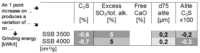
To date, research indicates that grinding energy for up to 3,000 blaine rises with:
1) increasing alite crystal size
2) increasing C2S content
3) fewer number of pores
Item [2] relates to raw mix chemistry. Items [1] & [3] relates to overburning. Large alites means over-burnt clinker thus it’s harder to grind. Clinker with a lot of pores are easier to crush. Some (not all) plants can monitor their grindability by watching the clinker literweights. As it rises, the clinker becomes over-burnt; sometimes balls up into bigger pieces; and sometimes it gets very dense (no pores). Good literweights are usually between 1250 and 1350. Watch out if gets above 1400. Note that some plants make a very fine yet seemingly hard to grind clinker. The researchers have observed that a high proportion of big alite crystals can be found in the fine sizes, in these cases.
On the other hand for fine grinding (> 3,000 blaine), the main factors become:
1) alite size, as before
2) C2S content , as before
3) grinding aid. Cost 0.6-1.2 €/t, usage 150-400 g/t.
As the cement particle gets smaller the pores disappear and no longer become a factor. Increasing the amount of grinding aid will make the cement easier to grind.
Hard burning = hard grinding. Hard burning may be necessary when the fuel burning is not optimal
Petcoke burning leads to harder to grind clinker.
FEED BINS
Typical problem: slag or other composite cements milled in systems designed only for OPC. Therefore 2 bins instead of 3 > often dosing problems since slag or other component is dosed with a front-end loader.
Or, there are 3 bins, but they are designed for clinker or gypsum and not the mineral component.
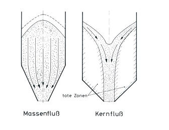
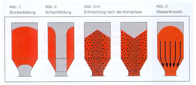
Feed bins have sides at different angles in order for the material to flow at different speeds. This imparts shearing forces on the material and thereby prevents accumulation of material in the bin corners.
Expanded Flow
Expanded exit flow means that the exit box diverges in the direction of the flow. This allows material from the part of the bin nearest the flow direction to fall.
This can also be achieved by having a straighter side in the direction of the flow.
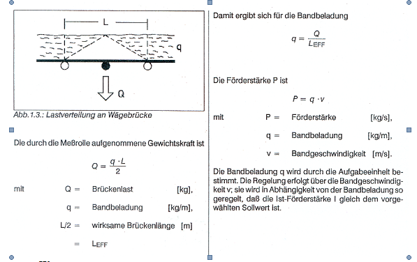
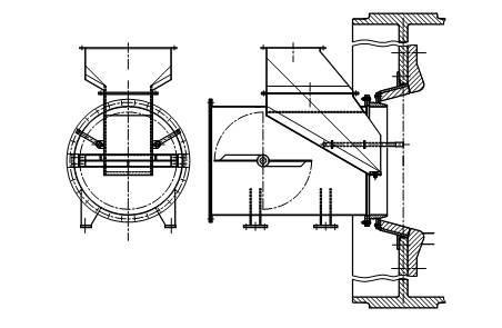
WEIGHFEEDERS
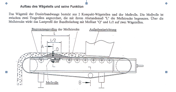
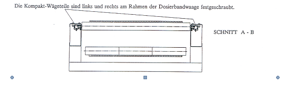
FEED ARRANGEMENT
Step-chute is favoured arrangement.
Slegten Modification to FLS mills:
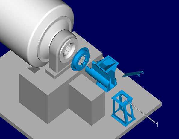
Above: Magotteaux modification to FLS feed chute in trunnion mill
Below: FLS feed chute (new generation into slide shoe mill)
DRYING
Drying Targets
Intermediate diaphragm 90-95°C. But Colonel = 65°C, without problems.
- Wireless mill inlet (did I mean intermediate diaphragm??) temperature probe:
- FLS $29,000
- KIMA $15,000 with electric ear
Drying Capacities
- End Discharge Mill max 4% drying with hot gases, 1.5% without
- Absolute drying capacity depends on the material size and if the moisture is surface or in the pores. Take example of sticky clay which rolls down preblending pile making large clumps à This is difficult to dry.
- 5-7% may be possible to dry without a drying chamber but accepting a lower production (depends if moisture is surface water or in pores).
- 1% additional water = 10% less capacity, when no excess of drying capacity.
- Greater than 7-8% definitely requires a drying chamber
- Max hot gas temperature 450°C for roller and 350°C for ball mill trunnion bearing (but note that Réunion is 550°C above trunnion), 250-300°C for roller press separator bearing.
- Center Discharge Mill: 1st compartment hot gases only, max 10-15% with kiln air + extra hot air.
- Air Swept Mill: no intermediate diaphragm (pressure drop too great). Therefore single compartment, therefore small feed granulo / low hardness particles required.
- Raw Mill Exit Moisture approximately 0.4%.
- 4 stage preheater systems are generally able to dry raw meal up to 8% moisture. 5 stage 6.5%, 6 stage 5.5%.
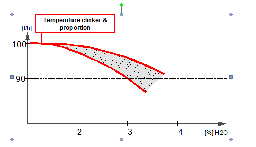
Drying without external heat source.
Percentage of total feed that can be dried is often largely a function of the clinker temperature and the proportion of clinker in the feed.
- Need to modify internals for increased gas flow.
- Drying must be complete by the end of the first chamber.
- Max Gas Air Speed (tube) <2m/s WITH hot gas only (otherwise 1.5 m/s). Can go >2m/s though if there is no excessive wear on the intermediate diaphragm and its centre screen.
- Max gas air speed (diaphragms etc) <25 m/s.
- Filter must be able to handle moist gas. Operate 30°C above gas dew point.
Actions to control drying when no external heat source available
- Increase drying by increasing energy input:
- Increase mill feed temperature
- Increase the separator returns, and/or increase its temperature by moving fresh air damper (but beware of maintaining the underpressure). For single-pass, recycle the gas from the fan outlet.
- Decrease mill ventilation (increases air residence time) à air gets warmer à increases amount of water that it can take.
- Increase Mill power in the first chamber (but beware of increasing kWh/t….).
- Possibly, use chemical admixtures, which allow drying of the water even at temperatureas around 80°C. Documented example from Barosso, Brazil à add up to 7% moisture with hot clinker 140-150° 25% slag but with no hot gas generator. Used by Votaratim and Lafarge in Brazil.
Drying compartment (ball mills)
Drying in a ball mill is called COMPOUND MILLING.
- Hot gases from hot gas generator <1300°C. Standard temperature with a hot gas is 400°C, ideal is 450°C. Need adequate cooling on the trunnion bearings. Max Bearing temperature typically 60-70°C (??).
- Introduce gases at <350°C if no drying compartment or drying compartment is integrated into the mill, <700°C if an overhanging drying compartment. Drying efficiency:
300°C = 220 kg H2O/m³.h
700°C = 350 kg H2O/m³.h
- Create tubulence in drying chamber by installing impact plate but watch for influence on the system pressure drop.
- Make sure that material is lifted to provide a full curtain of material. Watch for influence on the system pressure drop.
- Maximise retention time of the material by installing a weir at the outlet. Verify impact on the mill motor.
Drum Dryer L/D < 8.
Specific Load: <150 kg H20 / m³.h depending on internal fittings.
Dispersion Dryer – like a dryer in a tube mill.
Rapid Dryer – Drying rate 2500 – 25000 kg H2O/h
Dryer-Crusher – Air swept crusher with separator. For soft materials.
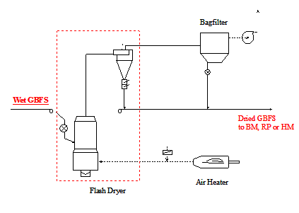
Flash dryer. Desagglomeraator breaks up feed which is fed to horizontal(vertical?) pipe where it meets hot gas coming from the bottom. The particles are carried upwards and dried at the same time. High gas speed required to compensate for terminal velocity of the particles. Material limit is function of pressure drop. Specific Load: <500 kg H20 / m³.h. feed size <20mm.
Kiln and cooler Air
Two sources for raw and cement grinding: KILN GAS and COOLER GAS.
- KILN GAS is often used for the raw mill instead of the cement mill because the temperatures are higher than cooler air (typically 300 –350°C) and the raw meal is generally more moist than cement. Kiln gas has high CO2 / CO content, and is therefore an explosion and safety hazard in the raw mill.
- COOLER GAS is used for cement mills because it is generally stable (more independent of kiln performance than kiln gas). Note however that cooler gas goes preferentially to the kiln air (high in O2), and only the excess supplies the cement mill.
60% thermal energy goes to preheater, 40% to kiln.
????
Overhung cooler is located on the other side of the trunnion. Often the metal is thinner etc because there is no ball charge. Dust Load at raw meal outlet.
Flash or Shaft Dryer
Conversation with Ole Rasmussen, FLS, October 20th 2005
- Shaft dryers operate with gas speeds up to 18-20 m/s.
- The drying ability depends strongly on the type of water (surface or inherent)
- Also depends strongly on the type of material and its granulometry and if it is porous or not. Slag for example is generally easy to dry.
- Tips for increasing residence time are to recirculate some of the cyclones material back to the dryer (use a splitter gate)
- FLS always design an reduction in the diameter (they call it a throttle) just before the feed point in order to increase the gas flow and therefore lift more of the larger particles up the dryer à higher residence time.
- Particles 15-30 mm are too big to be lifted up to the cyclones
- Indicated that 2% drying capacity is reasonable for Alesd.
- Kurt B. thinks that flash dryer internals are not used in the cement industry, despite what is shown in the books.
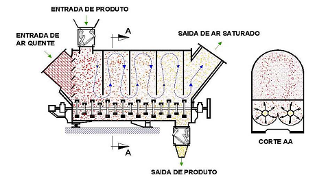
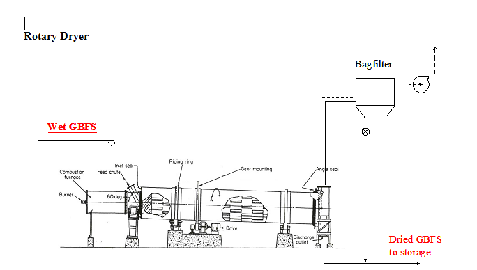
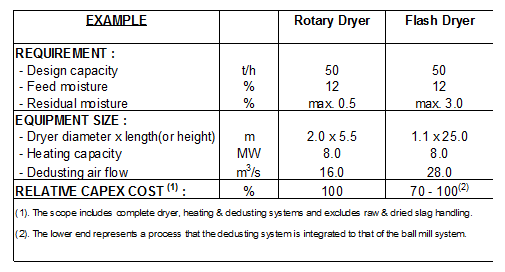
Rotary Dryer / Flash Dryer Comparision
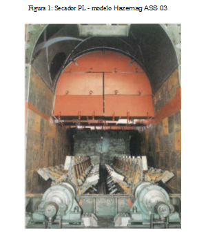
Hazemag – e.g. Pedro Leopoldo
Rotary Dryer
Grinding system Ball mills
Criteria for dryer sizing :
-Heating : direct-heat with a burner
-Material & gas flow : cocurrent flow
-L/D ratio: 2.5 – 3.5
-Drum inclination: < 4°
-Material filling ratio: 10-15%
-Drum rotation: 20-30% of critical speed
-Hot gas temperature: 500-800°C
Performance :
-Thermal efficiency : 50 – 65% (not insulated)
-Feed moisture : max.12 – 15%
-Residual moisture : <0.5%
Flash Dryer
Grinding system : BM, RP, HM
Criteria for dryer sizing :
-Heating : air heater
-Material & gas flow : cocurrent flow
-Hot gas temperature: 300-600°C
-Gas velocity : > 25 m/s
-Retention time : < 1 – 1.5 s
Performance :
-Thermal efficiency : 45 – 60 % (insulated)
-Feed moisture : max. 12 – 15%
-Residual moisture : 1 – 4%
Relative investment costs
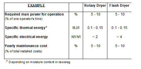
Operating Costs
HOT GAS GENERATORS
Fuel Sources
Kiln needs 3,300 MJ/tonne KK
Coal: 26,000 MJ/t
Fuel Oil : 45,000 MJ/t
Coal volatile matter 45% à accounts for difference in calorific values.
1 tonne coal > 8 tonnes KK
1 tonne fuel oil > 15 tonnes KK
Kiln 3000 t/d = 125 t/h.
Therefore 16 t/h coal required or 8 t/h fuel oil.
30% of HGG air is fresh air
HGG exit temp (combustion gases) 1869°C, O2 2%, CO2 10.5%, H20: 134 g/Nm3
8-9 litres of oil per tonne are required to dry a 10% blastfurnace slag in PL.
9 litres of fuel oil per tonne of coal are used in Chekka.
Pedro Leopoldo decreased from 11 litres to 7 litres per tonne of slag using oil.
As far as the HGG is concerned, I would measure the following:
- Amount of fuel used per hour (then check against my calculation)
- Amount of O2 and CO in the gas directly after HGG (no influence of mixing air) (incomplete combustion?)
- Temperature of hot gas (is it optimised – not too high = waste of fuel, not too low = dew point problems, again in my calculation you can play with that)
- Outside temperature of ducts (insulation OK)
- Operating procedure (timely start up to heat up system, switchover of fuels, not running unnecessarily, running too hot, etc)
If there is CO then there is a lack of Oxygen. There should be about 10% oversupply of O2 at least. check O2 in return gas ahead of HGG if it is a inert system. The primary air fan should give a good pressure to the burner, the head can be optimised to give a flame without any colour. No colour = good burning. If using solids, then check momentum thru burner and density phases in the solids flow.
Pressure of gas at HGG outlet should be constant -3 to -5 mbar. any variations (caused by feed maybe) will impact the burner and cause inefficient burning.Additionally, if you can measure at 90 degree angles multiple places you can check temperatures and verify good mixing downstream of hot and cold gases. (Remember my idea of using a drill and just boring holes in any place, that’s the idea here!)
It is critical if temp before mill is reading X and actually most of the gas has temp Y because of separated flow.
Heat Balance
Heat Balance
Heat Balance Program
This program has two aims:
- Calculate the fresh air required to cool the product to the specified temperature at the mill exit
- Calculate the quantity of hot gases required to achieve the product with the specified moisture
For the drying, the program first uses the kiln and cooler gases specified in the input section. If this is too much, it will bypass the mill and go straight to the filter. If it is not enough it will use gases from a supposed hot gas generator.
- The program calculates an estimation of the available KILN GAS based on kiln throughput.
- For the available COOLER GAS, need to ask TPT on a case-by-case basis.
- There is no direct to filter gas loop for cement and coal mills. The available amount of kiln and cooler gases must be modified manually to reach 0 m3/h excess gas.
GRINDING
Mill Speed
Critical Speed = 42.3/sqrt(diameter)
% Critical speed < 70 – “slow”
>75% – fast
70-75% – “normal
Mill L/D and Chamber Lengths
L/D
Kurt Breitschmid from ??? report: The mill with a L/D ratio of 2,9 [-] is rather short for grinding cement with a fineness >3’500 [cm2/g] according to Blaine.
Lafarge:
Raw Mills: L/D = 1.5 – 3.2
Cement Mills L/D = 2.8 – 3.2
HGRS:
Typical L/D is 3.2.
Chamber Lengths
Lafarge:
For blaine 3000, chamber 1 : 32-34%
For blaine 4000, chamber 1 : 26-28%.
For Raw Mill, chamber 1 : 35-45%
FLS Combidan Design Philosophy
FLS philosophy is of long 1st chamber and short 2nd chamber. In the second chamber there is a narrow range of ball charge and so there is no possiblity for classifying the charge. Therefore non-classifying (dragpeb) style liners are used. These liners should NOT be installed in a long second chamber or where there is a wide range of ball sizes.
The maximum ball size that can be used with these liners is 50mm.
FLS also supply traditional classifying liners on request.
According to FLS, the corrugated 2nd chamber liner provides the necessary lifting and also prevents slippage between liners and balls. Also maximises power uptake due to the thin profile (+2.7% kW compared to traditional classifying liner for a 4.6m diameter mill)
FLS mills have large centre openings. They allow the ball charge to be higher than the centre screen level when the mill is at stop because when the mill is running, the ball make a banana shape around the centre screen, therefore the screen is not damaged.
Dear Mr Ortega,
For closed circuit mills grinding OPC as well as CEM II type products, the FLSmidth default CII media charge is 40% 25 mm, 40% 20 mm and 20% 15mm (~38 m^2/t). This charge is combined with a relatively low design circulation factor, reflecting that the rather fine media charge works with good grinding efficiency up to ~2000-2200 Blaine at the mill exit. This also means that we would use the same design charge for say 12% R45 µm and 5% R45 µm, as the design circulation factor would be adjusted for maintainng an approximately unchanged fineness at the mill outlet.
A coarser CII charge wil have lower grinding efficiency and require a higher design circulation factor. This will give a coarser product at the mill outlet and thus reduce dry coating. The balance between lower grinding efficiency and reduced coating will depend both on the material and the Length/Diameter ratio of the mill.
Hoping that you will find my remarks useful, Ole S. Rasmussen
FLSmidth A/S
Process Design
Vigerslev alle 77
DK-2500 Valby
Phone +45 3618 2356
Fax +45 3617 1091
Quality criteria in mill and at mill exit
CEMENT Ball Mill
At Intermediate Diaphragm
- 0% water at the intermediate diaphragm.
- 15 – 25% R0.5 mm (Old Holderbank Manual)
- HGRS / LAFARGE <5% R2mm at the end of chamber 1 is the general fineness target.
- OR (LAFARGE) 86-92% passing 1 mm, 80-90% passing 0.6 mm, 75-85% passing 0.5mm
- Another is <50% R90mm sieve (this is also what we use for the grindability test).
Inlet 2nd Chamber
- <5% R1.2mm at inlet to the second chamber is necessary for a ball charge of 30mm.
At Discharge Diaphragm
- <0.35% water in the mill exit product since values greater than this may lead to hydration à reduction in strength. Keep dew point under 60°C and there will be no hydration ??
- Holderbank: 15-25% R90, max 5% R200
- Lafarge: <5% R0.5mm, <30% R0.2mm before the discharge diaphragm.
- Blaine at the end of C2 is usually half that of the final blaine, or 40-60% for typical circulating loads.
RAW ball mill
- <5% R 4mm at intermediate diaphragm (Lafarge), <5% R 2mm (Hanspeter).
- 50-60% R90 at the mill discharge (Hanspeter), 30% (Karl-Heinz).
- Typical raw meal blaine fineness 4200 cm²/g (Karl-Heinz). Isn’t it much lower??
Ball charge filling level
LAFARGE Recommended Ball Charge Filling Levels
Relationship Mill kWh/t and Ball Charge filling level
- Austin, Klimpel and Luckie – „Process Engineering of Size Reduction: Ball Milling“.
- U = volume of material / empty volume between balls
- X-axis Ballcharge filling level
- Y-axis specific electrical energy consumption of mill kWh/t mill.
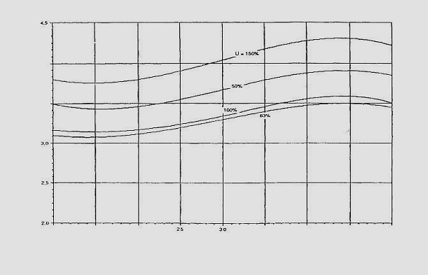
- Energy Input for Cement Grinding, von H.-G. Ellerbrock and B. Schiller, Dusseldorf, ZKG – Nr. 2/1988)
- Review of 11 mills showed the following results. They used kWh/t of mill throughput as a bench mark given that they were grinding to a mill exit of 1800 cm2/g. All mills were running at 55% to 75% of critical speed.
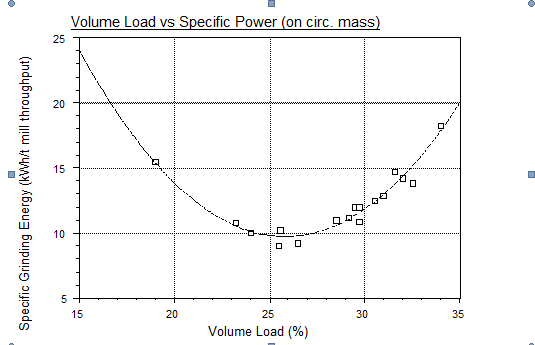
Practical results: Azergues. 100% > 72% of the charge (= 30% filling à 21.6%). Throughput 100% >80%. KWh/t mill 100% > 91%.
Relationship Throughput and ball charge filling Level
- Austin, Klimpel and Luckie – „Process Engineering of Size Reduction: Ball Milling“.
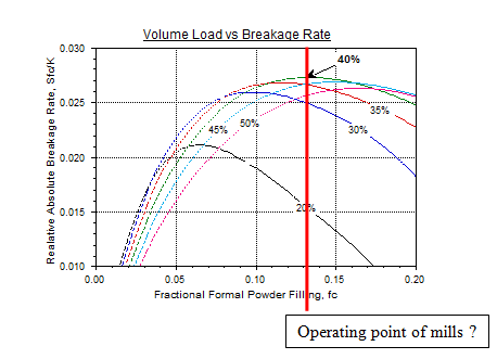
Conclusions:
- 40% filling gives maximum production.
- 40% gives 3.8% more production than 30% if the material level is optimised.
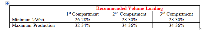
Lafarge best practice: in a non-sold out market, it is typical to maintain the 1st level charge at 26-28% filling in order to optimise kWh/t without penalising production too heavily. The second chamber is usually 2% higher than the 1st chamber level i.e. 28-30%.
Loading can be reduced to 22% filling for OPTIMUM kWh/t if production really isn’t needed. This is a STRICT MINIMUM due to increased likelihood of damage on shell liners in C2.
For high market demand, increase the filling level in the C1 to 32-34%, C2 34-26% according to:
- Mill installed power
- Stress on gearing
- Stress on mill shell
- Drying capacity
- Separator efficiency
- Other constraints
Ball level in the inlet trunnion max 50-75 mm above the level.
When filling levels in C2 are >34%, the effect of classifying liners in often lost.
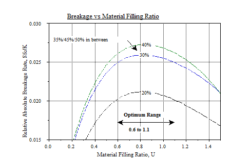
Material filling level
Relationship Crushing Efficiency and Material Filling Level
Optimimum filling level occurs between 0.6 and 1.1. This is independent of the amount of balls used. BUT: SEE Austin, Klimpel and Luckie which suggest the opposite.
Ball Charge Classification
Ball charge classification works best in small mills. (stéphane)
Swelling of charge / Reverse Classification
Robert’s Experiences:
- Joliette: 2 different liners used in a monochamber mill. At this point, the ball charge size distribution is mixed
- La Réunion. The plant used 2 very similar classifying liners of the same dimensions and wear profile. Nonetheless, where the 2 liner types met, there was a strict line defining the loss of the classifying action
- ?? Can’t remember plant: The mounting of the classifying liners was slightly wrong – there was a 2 cm gap between liners in the middle of the chamber, which was filled with a ring of 20 mm balls. At this point, as strict disruption of the classifying effect was observed
- Many mills: where unground clinker particles get through to the 2nd chamber, they cause localised swelling of the charge. Often, the smaller balls then migrate to the middle of the chamber leading to swollen mounds in the middle of the chamber.
Others’ Experiences
Hanspeter example: Germany? During performance test material filling level was high and ball charge reverse classified. Reduced feed and filling level and after 1 day the ball charge was reclassified.
LAFARGE:
Reverse classification occurs when particles greater than 1/3 the diameter of the void space between balls are NOT crushed immediately. The reasons are:
- Feed granulometry or hardness too much for ball charge
- In the first chamber, inefficient crushing due to ball charge too small or liners too worn
- Ball charge too large in the 1st chamber combined with diaphragm slots too large à large particles get into the 2nd
This problem can be detected by:
- An overall filling level more than 3% greater than the calculated filling level
- In C1 often the balls are visible but the overall level is more than 3% above the calculated value.
- Alternatively the first part of the C1 might be swollen (especially with high returns load) and the zones behind are empty because the retention is greater in the swollen area. In such cases there may be an inverse classification of the charge (see next point)
- Reverse classification in 1st or 2nd In this case the material is carried by gravity down the “slope” along the length of the compartment. In addition it is noticed that the balls in this area migrate down the slope too and they may stop in the middle or the end of the compartment. Often it is the BIGGER BALLS THAT MIGRATE à reverse classification in the C1 and C2.
- High variations in power draw at the mill motor
Residence Time
Open Circuit: >=12 minutes
Closed Circuit: >=5 minutes
Test using fluorosceine, mixed in a bag with some clinker, then added to the feed belt. Sample at mill exit every 30 seconds for a period of ~25 minutes after adding the clinke+fluorosceine. Need specialised measuring equipment in lab.
Ball Coating
Ball and liner coating can occur in raw as well as finish grinding. Ball coating can be a result of the following conditions:
- Inadequate Grinding Aid
- Poor Mill Ventilation
- Mill Overheating
- Too Much Moisture Input
- Mill Overloading
Adequate ventilation will help alleviate persistent problems. Mill ventilation can serve two purposes to reduce ball coating in mill temperature problem situations. It can take heat away from the mill as it is created by the grinding, and it can take water vapor away from introduction with the material or from water sprays which provide additional cooling.
The present theory concerning ball coating is that as the particles of feed shatter under the impact of the ball charge, the surface equilibrium becomes unbalanced. This unbalanced condition causes an attraction between the individual particles of feed and between the feed particles and balls resulting in ball and liner coating, material agglomeration in the mill and “pack set”. Ball and liner coating cushions the impact of balls, and in severe cases can affect lift. Material agglomeration affects grinding as well as separation.
Pack set is that condition where bulk cement, after being compacted by vibration, requires considerable mechanical effort to start initial flow. Actually, pack set bears much the same relationship with cement flowability, as starting friction bears to moving friction. Pack set, like starting friction, requires more force to start material flow than that required to keep the material flowing. Pack set has become a serious problem in recent years because of the cement industry’s use of large diameter mills which causes a higher material surface unbalance and the increased transportation of cement in bulk quantities.
Grinding Aids
The addition of a grinding aid spreads the feed particles farther apart, thus exposing more surface area to the grinding media, resulting in increased production. The grinding aid adheres to the individual particles, thereby restoring the particles to a balanced state, thus reducing agglomeration, ball coating and pack set.
The quantity of grinding aid used in a particular mill is dependent on the size of the mill, feed size, product size, type of clinker being ground, etc. For instance, in large diameter ball mills, the impact force of the grinding media is so great, that a high material surface unbalance prevails in the mill when grinding all types of clinker, thus requiring a grinding aid at all times.
The higher the fineness, the more grinding aid that must be used to restore the feed particles to a balanced state. Normally, grinding aids are added in a 15% concentrated solution (1:7 grinding aid to water – helps the dispersal of grinding aid in mill), at approximately 2-2.5 Lb./Ton for medium fineness and 3-4 Lb./Ton for high fineness cement. (Check with your supplier).
Willi Suter Presentation
Price
1300 – 2000 $/t
Dosage rate 200-400 g/t
0.26 – 0.8 $/t clinker.
Effect of grinding aid on kWh/t
- Reduces coating onliners
- Reduces blaine for the same residue 45mm
- Enhances flowability, reduces agglomeration > better separation, less bypass
- Gives quality impact on aggregates in concrete as well as cement.
- Rochefort €150,000/ year on grinding aid.
- Also useful for slag.
- Also work in Vertical Roller Mills.
- Good ventilation helps dispersion.
- Typical dosing range 100-300 g/t (pure), optimal 180-260 g/t.
- Threshold value 150-200 g/t
- Typically 300-400 for a cement 3000 to 4000 blaine, 350-400 for higher blaines.
- Effect of ground limestone important??
- XEU242P Never go below 350 g/t.
Effect of grinding aid on product quality
- Depends according to the grinding aid and cements concerned
- Flowability is improved à improvements or problems for transport and packing
- May help reduce the water requirement by acting as plasticisers. The reduction in water demand consequently leads to a higher compressive strength.
- Mortar and concrete may have an increased tendency to bleeding.
Spitzers (Unground Clinker)
Spitzers can cause the production of superfines which in turn affects blaine. See Lafarge high blaine, high rejects problem. Note that hydrated clinker e.g. after long period of storage outside, can cause a large number of hydrated superfines which add nothing to strength development.
GRINDING TOOLS
Ball Charge
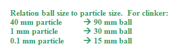
The reasons for the optimum are as follows. If the balls are too small then they don’t have the inertia to properly nip the material and break it. For example; grits (or spitzers) in the second compartment, the cascading small balls don’t hit with enough force to fracture the grains so they are worn smooth at a slow rate and retained in the mill, causing material transport problems.
If the balls are bigger than the optimum for the feed size then the lower number of contact (nip) points reduces the specific breakage rate. Note that if a particle size is smaller than either the optimum for both the smaller or larger ball the specific breakage rate of the smaller ball is superior, this is why finer balls in the second compartment work well.
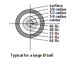
Relation ball size to particle size. For clinker:
Ball weights sizes and densities
Ball weight = [diameter (mm)]3 / 250
LAFARGE
Ball Size Density
3.5 – 2.5 inch 4550 kg/m3
2.5 – 3/4 inch 4650 kg/m3
HOLCIM
Ball Size Density
90-60 mm 4.4 t/m³
50-30 mm 4.6 t/m³
30-20mm 4.7
1st chamber: 4.4, 2nd chamber 4.65 used by Holcim
WARNING: Depending on the source foundry bulk density values have been known to vary considerably.
Ball Charge Specific Surface
= 785 / d (mm) m2/t
Ball Charge Condition
Stefan Evers and Stephane: There is no contractual specification for the condition of ball charge
There is a general contractual specification that <3% of charge breaks after being in the mill.
Example of delivered ball charge in La Réunion from a South African foundry (license(?) Maggotteaux.):
- Mixed 17/20mm balls
- Recycled drums
- 60mm with lumps and seam
- Small balls still with mould defects
Monochamber and Raw Mill Ball Charge Design
LAFARGE: Polysius model suits these mills well:
D = 9.6e^(-0.13x)
where x is the effective mill length.
BALL WEIGHTS AND SIZES (New Grinding Media)
High Chrome Cast Iron Grinding Balls
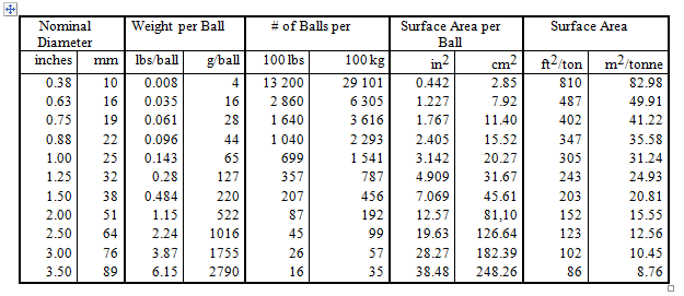
Data supplied by ME International (1990)
Data based on steel density of 7559 kg/m3 or 471 lbs/ft3
WARNING: values may vary from supplier to supplier. The above table should be considered as approximate values. Sampling is recommended for bulk density and porosity index calculations.
1st Chamber Ball Charge Design
Biggest ball size – bond formula
100mm balls
- The use of 100mm balls is possible, but should be avoided as wear and liner damages will increase. In this case, the usage of 60mm balls should be reduced to a minimum.
- Big balls climb to the highest position à increased wear and breakage of liners and other balls.
- Bigger balls means less balls which means less contacts which means less crushing
90 mm 3 kg/ball
100mm 4 kg/ball
110mm 5.5 kg/ball
Raw mill
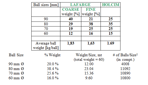
For the RM it is considered to have 40% – 45% of the total mill power consumption in the first compartment.
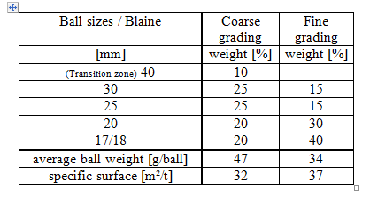
For raw mills it is most common to use a ball charge with the coarse grading (up to 50% of 90 mm balls) – see table below for “coarse” grading.
Cement Mill
The ball charge tendency in the 1st compartment is to use the coarser of the gradings available. When producing high Blaine Cement it is the objective to use less tonnage. Achieve nearer 8-9 kWh/t at the target mill output instead to go for a more fine ball charge (??)
- Standard design is adapted for 3200 cm²/g.
- Slegten Ball charge is same as Polysius for the 1st chamber, and finer for the second chamber.
- Smallest size = 2x diaphragm slot width
- Standard optimisation is to reduce the power drawn in the first chamber by liner and ball selection (coarser / finer)
Lafarge Design vs. Holcim
Using a pre grinding circuit the maximum ball size could be as low as 60 mm. These cases are very specific and can not be published as a common solution.
Some plants use on 90, 80, 70 mm balls in 1st chamber. E.e. San Sebastien.
2nd Chamber Ball Charge Design
Discussion
IF THE SEPARATOR IS OVERLOADED, USE A FINER BALL CHARGE SO THAT THERE WILL BE LESS CIRCULATING LOAD AND THEREFORE LESS SEPARATOR BYPASS.
Transition zone charge
ONLY FUNCTIONS WITH A CLASSIFIED CHARGE
The purpose of the transition zone is to grind the oversize that manages to get by the partition which is too large for the main second compartment charge to grind. Usually it is composed of 2, (sometimes 3 sizes). In metric, we usually pick 50 and 40 mm Ø’s. In U.S. units we pick 2″ and 1.5″ Ø’s. The transition zone constitutes the first part of the second compartment.
In any case, for each size in the transition zone we extend the value (N) and the use the exact same number of balls for each size. Back-calculating we can then determine the weight and the percentage that represents.
Note that transition zone design can only be used effectively if there is a good classifying action from the liners. Most people also get a little nervous with such a small tonnage in the transition. Thus in practice they tend to be larger than what is recommended by the Slegten model.
2nd Chamber Ball Charge – Bombled Versus Polysius and Slegten
Comparing the two curves we can observe that the 1989 design has a slightly coarser ball charge in the first compartment than what the Polysius model would suggest using, (average ball weights were calculated to be 1.65 kg/ball vs. 1.5 kg/ball respectively). However it’s the reverse in the second. In fact Polysius model does not recommend any 0.75″Ø balls at all.
Comments:
In general the Polysius model is simplistic – one curve fits all mills. As a rule of thumb, it suits raw mills and especially monochambers very well. Solutions will tend to have coarse second compartment ball charges.
The Slegten model divides the mill ball charge into 3 parts: first compartment, transition zone and the second compartment. The approach in designing the ball charge is different in each. However, a recommendation from Slegten will vary from their own model since they take into consideration field inspections, their own experience, and their own rules of thumb for mill idiosyncrasies. (They are not all that different from the rules discussed in “Practical Fundamentals …. Volume 1”.) This is after all how they make money on consulting. In general the Slegten model is compatible only with mills with classifying linings in the second compartment.
Notes
- non-classifying liners only permit 3 ball sizes in C2.
- Lafarge recommended top-size 30-40 mm (2002).
- Standard optimisation is to maximise fine grinding using balls 25mm – 15mm.
Bombled distribution is standard for closed circuit coarse (OPC) cement:
Is based on assumptions:
1) Optimum ball sizes are related to particle sizes according to the following equation: d1/d2 = (D1/D2)1.7
d = particle diameter
D = ball diameter
- Particle size distribution along the mill axis can be expressed as a function of % residue at particle size di:
Raw Mill
It will be beneficial using a finer ball charge. The limit is given by the slot size of the partition wall.
Cement Mill With Classifying Liners
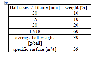
SLEGTEN
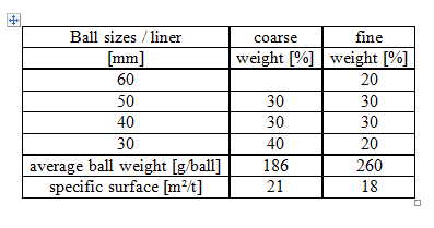
The second chamber Slegten standard ball charge composition for an OPC cement varies with the cement fineness as indicated in the table:
The repositions to keep the ball charge parameters constant are calculated according to Slegten criteria.
As an indication the HMC standard ball charge for 3’000 [cm2/g] has 62 [g/u] and 29.4 [m2/t] as average ball weight and charge specific surface respectively.
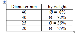
HOLCIM
Closed circuit for clinker cements ( > 90 % clinker):
Cement Mill With Non-Classifying Liners
Here, the grinding efficiency and the manufacturing technology for the balls do not allow one to use a large variety of ball sizes. Usually, the range in Ø, (from largest to smallest) should not exceed 0.75 inches (~20 mm). One must make a compromise then, between using very large Ø’s or very small Ø’s in the second compartment. Your choice must take into account the effect of porosity will have on throughput and the separator. If you work with too many sizes in such a compartment, then you’ll experience reverse or double reverse classification and a drop in production. It is better to work with a fairly flat gradation of ball sizes.
Ball charge design for non-classifying liners
Open circuit cement mill
SLEGTEN
The charge composition is also adapted to the cement fineness:
HOLCIM
Calculation Procedure For A Composite Cement
Composite cement equivalent OPC fineness calculation:
When composite cements are ground the fineness according to Blaine is not anymore as reliable as with OPC. A fineness correction must be introduced.
According to Slegten laboratory to calculate the equivalent OPC fineness of composite cement the following values:
Ø Gypsum: 125 * (actual gypsum content [%] – 5 ),
Ø Limestone: 50 * actual limestone content in [%],
Ø Puzolanna: 40 * actual Puzolana content in [%],
Ø Fly ash: Fly ash fineness [cm2/g] * actual fly ahs content in [%].
must be deducted from the composite cement actual Blaine value.
Ball charge calculation:
Ø The OPC equivalent fineness must be calculated for every cement type ground in
the mill being studied.
Ø The ball charge will be chosen from table 1 or 2 (closed or open circuit mill)
according to the smallest OPC equivalent fineness calculated.
Ø If the OPC equivalent fineness is, for example, 3’700 [cm2/g] interpolation of the
ball composition given on the tables must be done.
Ø The [%] of balls ranging from 60 [mm] to 40 [mm] has to be adapted to the
operation condition of the first chamber (specific energy given to the material, state
of the liner, of the ball charge and of the diaphragm):
© If the first chamber supplies no coarse material to the second chamber, a
smaller amount of these balls than reported on the tables will be required,
even the suppression of the biggest diameters.
© On the contrary, when coarse material can be supplied to the second
chamber the amount of these balls reported on the tables might be
increased.
Ø The calculated ball charge must always be compared to the actual ball charge
because:
© a coarser ball charge might led to a loss in grinding efficiency,
© if the actual ball charge is finer than the calculated one the interpretation of
the process parameters of the grinding circuit will help to decide if a finer
ball charge composition will allow an even better mill operation.
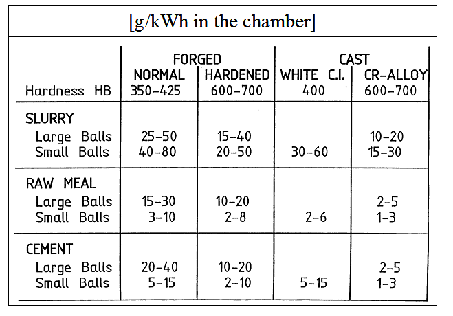
Ball Charge Wear Rates
Net wear rate = process wear rate (loss of tonnage inside the mill during grinding)
Gross wear rate = purchasing wear rate (takes into account the balls thrown away during sorting, either too small for compartment or scrap), is therefore more than the net wear.
A rough estimation can be calculated considering a global net wear rate of 1.1 [g/kWh] (Stephane). Gross wear rate 1.5 g/kWh (my estimate). Wear rate is the same for raw material and cement. Different for slurry grinding (6 times more).
This value can change a lot depending on the cement composition and the abrasivity of these components. For example, for pure slag grinding the value can be doubled.
Specific ball wear costs
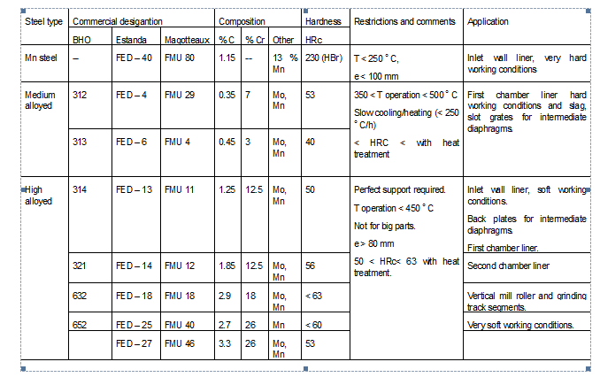
Ball charge metallurgy
Compartment 1
Low Abrasive Material: 2.5% Carbon,17.5% Chromium
Medium Abrasive Material: 3.0%, 20%
High Abrasive Material: 3.0+%, 20%+
Compartment 2
Low / Medium Abrasive Material: 3,0% Carbon,12% Chromium
High Abrasive Material: 3.0%, 20+%
Application:
The working conditions of a liner are “soft” when:
– the filling degree of balls in the chamber is above 28 %,
– the level of material in the chamber is good,
– the mill critical speed is below 76 %.
In any other case the working conditions are “hard”. If more than one of the above-mentioned points are given during a mill operation the working conditions are very hard.
If the operating conditions are much more favourable than the one above (speed far below 76 % and/or filling degree >>28, the material level in the chamber is good) the working conditions are very soft.
Restrictions and comments:
- To avoid changes in the steel structure and therefore damage of the liner, the indicated operating temperatures (T operation) must not be exceded. Also heating up or cooling must be done according to the indicated gradient temperature.
- For high alloyed steels a perfect support of the plates must be granted to avoid plates breakage.
- For medium and high alloyed steels the hardness can be modified through specific heat treatment to reach a better compromise between wear and impact resistance.
Note: for identical liner design, alloy composition and heat treatment the lifetime
reached will be the same and independent from the liner manufacturer.
Estanda: In first chamber design for maximum 3% expansion of the ball charge. (Also Lafarge)
Estanda: In second chamber design for a maximum of 2% expansion in ball charge.
Liners
Impact on Process
LAFARGE: 8 – 10% production loss when lifting liners worn
Process Design
Correct design is a function of the expansion of the charge which allows material to penetrate the charge, and the lifting angle defined as the angle between the vertical and the line between the top ball and the centre of the mill.
1st compartment – low hardness, high impact strength. Opposite for 2nd compartment (abrasion resistant).
Manganese liners – small mills, more deformation
Low Chromium – big and small liners, less deformation
High Chromium alloyed cast steel – Most Used, impact strength 4-10 J/cm²
Classifying: every row for small mills, every two rows for medium mills, every 3 for large mills. Classifying angle increasing with mill size.
- Classifiying liners only work if ball filling level is <35% and chamber L/D is >1.5.
- The flat parts are corrugated, and the sloping parts are not. Therefore………
- Above volume load of 34-36%, the traditional classifying liner breaks down.
- NOTE: The X-Class classifying effect breaks down at critical speeds >80%.
- Typical production rate increase from non-classified to classified à 6%. This is because the classifiying liner allows the efficient use of the existing fine ball charge, and further, allows a further increase in the amount of fine ball charge.
Grooving of liners is due to bolting (?? Info Magotteaux).
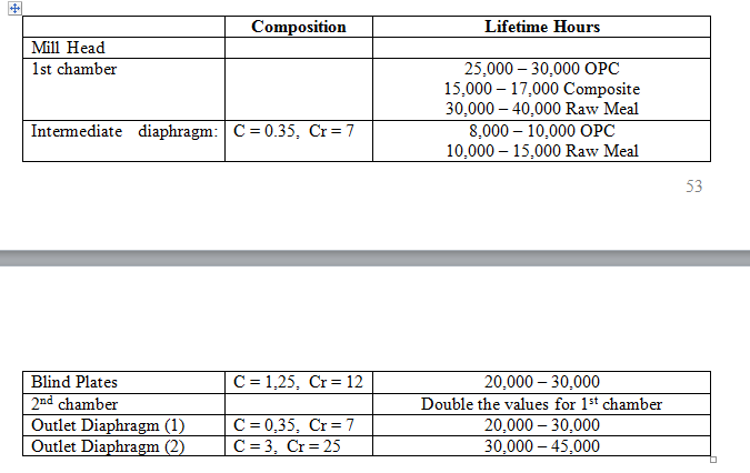
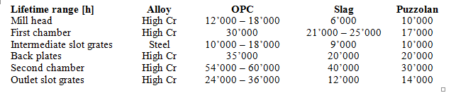
Lifetimes:
OPC 25000+ hours 1st chamber, 50000+ 2nd chamber.
Raw Meal: 35000 hours 1st chamber, 70000 hours 2nd chamber.
Rubber Liners – Wet grinding (steel corrosion, good abrasion resistance for balls<65mm)
Conversion from non-classifying to classifying liners in short mills can reduce filling capacity by up to 5% (check!)
Liner Bolting
Diaphragms
Diaphragm Design
10-20 cm2/tph
Selecting Diaphragms
The type of diaphragm that suits a defined application can be found based on the following criteria: Mill type: cement mill, dry process raw mill, wet process raw mill.
- Diaphragm location:
- Raw mill: transfer diaphragm at the drying chamber outlet, intermediate, peripheral discharge for a double rotator mill and outlet diaphragm.
- For a cement mill: intermediate or outlet diaphragm. For the case of
cement mills with a drying chamber see raw mills.
- Mill working conditions:
- ventilation air speed through the mill. Bigger or smaller than 1.2 [m/s].
- Material abrasivity. The [%] of slag or pouzzolana content on the fresh mill feed for cement grinding. The [%] of free silica at mill feed for raw material grinding.
- Moisture content of the mill fresh feed. Above or below 2 [%H2O] content.
- The diaphragm type: the name indicated refer to Magotteaux – Slegten denomination. For details about each type of diaphragm, please, see B14.2 reg. 8 and B14.1 reg. 2.
- Diaphragm characteristics
- The diaphragm frame can be manufactured or cast. The second one is only use in special applications where wear is very high.
Drying Compartment and 1st Chamber
Needs to be shock resistant up to 400°C
Needs to resist forces of ball charge in C1
Tend to be very open to allow passage of the gas.
Machined plates have a greater lifetime than cast plates of the same slot width.
Intermediate:
Chekka > trunpet at the exit of diaphragm lets material flow out of diaphragm outside the air stream BUT also accelerates the material in the gas stream > uses less of C2 charge.
Most important design criteria are the slot width and total slot area.
From Lafarge best practice papre, experience shows a 5% increase in mill throughput when installing a flow control diaphragm after a non-flow controlling diaphragm.
Tangential slots – better material flow
Radial slots- reduce probability of clogging
Slot plates made of up to 27% Chromium
Pfeiffer design makes the material flow out of 3 and 9 O’clock positions thereby not entraining the material in the air-flow > increase in effective grinding length + reduced wear of balls near diaphragm.
Weight of airfeel diaphragm in mill 5.2 metres diameter > 30 tonnes.
Front plates
- Cement slot width: Slot width normally 6mm, but may be 8mm in the case of moisture content > 2% in order to avoid clogging.
- Raw Meal slot width: 8mm intermediate
- Concentric slots lead to less blocking
- Thickness is 40-60mm when new, 15-30mm when worn out, Pfeiffer 8-10mm.
- Inside rings wear faster than outer rings.
Back Plates
- Thickness is 40-80mm when new, 15-30mm when worn out, Pfeiffer 8-10mm.
- Plates with slots provide less resistance to air flow, but impact negatively the material flow control.
Central Opening
- Should be as large as possible for minimum air resistance, may be adaptable to the filling level.
- Grate is only a security measure against balls passing between chambers in the event of a blockage.
End diaphragm
Centre discharge mill – single diaphragms, slots 2mm larger on fine compartment side.
Low wear rate.
Slot width:
OPC 7-10 mm
Raw Meal 12-18 mm
Mill Head
Tendency to use slide-shoe bearings on large mills. There are too many stresses on large mills which have trunnions.
For trunnion mills, the end plate is either welded directly onto the shell or is bolted. The end plate is usually bolted to the trunnion unless it is cast as one piece if small. For proper direct welding a steel with low sulphur content is required.
Conical with trunnions.
Flat with shoe bearings.
Mill head plates which get damaged > plates circulate in the mill and damage the liners.
Mill Shell
- Mill Shell – thicker in the middle.
- Trunnions afford greater bending stress (12 – 18 N/mm²) compared to 9-10 for shoe bearings. 6-8 for centre discharge mills.
Mill Ball Charge and Internals Lifetimes
Ball Charge
Magotteaux Rules:
OPC 2800-3200 cm2/g lifetime 100%
OPC 4000-5000 cm2/g -15%
Slag Cement 2800-3200 cm2/g -20%
Slag Cement 4000-5000 cm2/g -30%
FLS wear rates for ball charge:
Liners
Hanspeter Library Card:
The graphic below gives the distribution of the gross and net wear rate in the Group for cement grinding based on ATR 1’998.
The average net wear is 14.9 [g/t] while 28.7 [g/t] for the gross wear rate. This means that about 50 [%] of the liner weight is not being used. Known cases show that within 15 – 20 [%] of the liner initial weight can be worn before the liner looses its function.
MILL VENTILATION, DEDUSTING and Filters
Pressure Drops
Turbulent Flow:
P2 = P1.(V2/V1)^2
Laminar Flow:
P2 = P1.(V2/V1)^1
In a vertical mill:
P2 = P1.(V2/V1)^1.5 (hence some laminar flow through nozzle ring)
In a bag filter:
P2 = P1.(V2(v1)^1.4 (due to laminar flow through bags. Only turbulent at inlet and outlet)
Mill ventilation
Objectives:
- Primary objective is the removal of fines
- Secondary is the removal of heat (a heat carrier)
- Third is fluidisation or movement of material through the mill
Need >30°C above dew point in mill filter.
Target 100°C at the intermediate diaphragm, and less than 90 at the mill outlet? Drying must be completed by the intermediate diaphragm.
Air temperature is generally 5°C lower than clinker temperature. If even lower à false air.
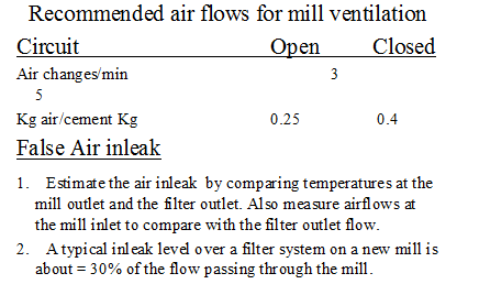
Notes from Alesd:
- FALSE AIR RAW MILL
- Best practice Jerez: 35%
- Addition of flaps at raw mill exit reduces false air 5-10% (Walter)
- Most important is reduction of underpressure at the mill entrance / exit (Alesd)
- Cost of rotary valve feeder:
- 52000 euros ex works for 200 t/h (Polysius)
- Estimated 70000 euros for 300 t/h
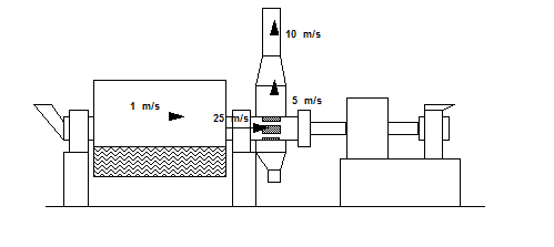
Mill ventilation velocities
To fine dust at the mill filter can lead to to quick bag penetration with fine dust resulting in shortened bag lifetime and increased pressure drop
Bag wear is not only a function of dust load but also depending on ducting and filter inlet design as well as air speed at the ilnlet of the filter.
Lafarge allow up to 3 m/s above the ball charge in raw mills.
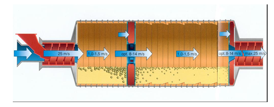
Above the Ball Charge
Typically we target 1 m/s above the ball charge or greater. However this is very difficult to achieve. When determining this value watch out for inleakage around the hood and back drafting through the discharge airslide. They tend to inflate mill sweep velocity estimates. As a general rule old mills (pre 1980) tend to have small trunnions and are impossible to vent
above 1 m/s.
Figure 1: Typical Mill Vent Velocities
Discharge Trunnion
As a rule of thumb, the maximum vent velocity through the discharge trunnion is 23 to 25 m/s. To achieve higher usually requires such a large pressure drop that most dust collectors and fans are not designed to make this practical. To estimate the maximum venting volume flow, take the smallest available cross sectional area; deduct 40% to allow for material in the trunnion; multiply by 25 m/s.
Discharge Hood
Normal maximum dust density to a filter is 200-300 g/m³. This equates to a gas speed at the exit of the drop-out box of 4-5 m/s. Older mill systems of course may not respect this, however this is the design value for new mills or for modifications. For higher velocities there is a tendency to entrain too much dust. This usually leads to a variety of operational and maintenance problems in the ducting and the dust collector.
A gas speed of 4-5 m/s exit drop-out box and a mill speed of 1.5 m/s generally gives a blaine of the aspirated dust of ~3000 cm²/g (Beat Stocker).
A gas speed of 2-2.5 m/s exit drop-out box (mill speed 0.5 m/s) gives a blaine of ~4000 (Beat).
Discharge Duct
Typically we find that the discharge vent duct is sized for about 10 to 15 m/s. We surmise that this is only to prevent settling. If the plant wishes to install a drop out chamber, to create a poor man’s static separator then design for 1.5 to 2 m/s for normal cement.
Static Separators on the Mill Ventilation
These units work just like the two separators in series in one respect and like two separators in parallel in another. All of the feed that goes to the static separator (generated by mill sweep) is essentially double-classified. First by the static and then again in the dynamic separator (static rejects go to the elevator). The second nice thing is that the feed to the dynamic is reduced by the amount of product pulled off by the static. Thirdly, the fineness of the feed to the dynamic is reduced, this appears to improve its performance too. Fourthly, if your dynamic is a Sturtevant you will likely find the quality of the product from the grit is better than your separator fines, Rosin-Rammler speaking.
The trick here is to get as much material as possible to the static. This means maximum mill sweep. Demopolis gets half of their mill exit material to the grit first, but it takes 1.6 m/s above the balls ( and a 400 HP fan) to do it.
If you have an H.E.S., the value of adding a static is questionable since the separator is so efficient already – it won’t know the difference. Quality may suffer too. The static’s generally produce cement superior to a Sturtevant, similar to a Raymond, and worse than an H.E.S. based on Rosin-Rammler. In short follows these rules of thumb:
Pursue a static if you have the following combination;
- Sturtevant or Raymond
- potentially good mill sweep
Don’t bother if you have;
- an H.E.S.
- an F.L.S. mill with little trunnions
- other mill sweep limits (D.C.?)
As an alternative consider also a large dropout box (poor man’s static) if you have the room, but not the money. (Exshaw FM2)
Ventilation Limits
- Abrasion of mill internals
- High drag force leads to empty areas at entry of C1 and C2.
Mill Fan (Ball Mill)
- (BCI) Benchmark fan kW is 15-25% mill kW for sufficient RAW MILL drying. WHAT!! Alesd = 320/5200 = 6%.
Auxilliary Dedusting
Ducting
Bhatpara, ducting at the exit of the 51 Dorol is about 15mm thick. Delivered with spiders inside in orderto maintain the shape of the parts.
Dedusting ductwork design. 16 m/s for slag and clinker, 18 m/s for the rest.
- 2000 m3/h for average point, no more than 2750 m3/h
- 18 m/s for ductwork airspeed – air quantity comes from air slide injection quantity etc.
- 1.5 m/s for hood airspeed
- Dedust blaine 5000 for cement transfer point
- Dedust blaine 3000 for clinker transfer point
- Flowrates of different points need to be balanced, or at least a system to balance.
Rochefort example (Beat Stocker):
For 5 dedusting points = 5 * 2000 m3/h
New filter and dedusting = €80,000
Redo ducting and hoods = €3000 per point
New hoods only, around = €1000 per point
Example Stéphane cement course. Elevator dedusting located in wrong position + incorrect hooding à extraction of large quantity of fines from elevator. Then discharged from auxillary filter onto VRM feed belt à mill vibrations and mill stop.
Dedusting Hood Design
Bag Filters
Respected Sir,
I would like to know about Clicker Size ( 0 to 5 mm ) while using Pet coke 100 %
in kiln
also tell me how much it will come and on what factors it depends means how could we decrease or increase 0 to 5 mm size Clinker % age
waiting for your Answer
Ali Abidi
It is a good compilation. Details of VRM and HPGR are not as much as of Ball mills.
Good information about ball
cement mill