Contents
Everything you need to know about cement Materials Preparation and Raw Milling
[wpecpp name=”package” price=”75″ align=”center”]
by A. K. Chatterjee*
Limestone and other naturally occurring compact raw materials are usually received in a plant from the quarry in maximum sizes of 1 to 2 m. In order to convert these raw materials into clinker and cement, it is necessary to produce a raw mix with a top size of about 0.2 mm. The reduction ratio required for most raw materials is consequently 1000-2000:0.2 or 5000-10,000. It is obvious that such a degree of comminution cannot be achieved through a single machine or a one-stage operation. Further, following the stage of comminution, good homogeneity has to be achieved for the raw mix, as this is essential for product quality and plant efficiency. In parallel with this, it should also be borne in mind that in order to ensure continuity of the manufacturing process, stocks must be built up at various points. Typical quarrying of limestone followed by crushing and conveying to a cement plant is shown in Figure 2.3.1.
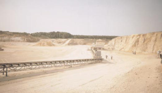
Figure 2.3.1. Limestone quarry showing crushing and conveying operation to storage silos.
The process route for raw materials preparation is multi-stage and complex. It generally consists of such steps as:
• Crushing (one-, two- or three-stage)
• Prehomogenization and storage of crushed materials
• Grinding (diverse milling systems)
• Proportioning, homogenization, and storage of fine material
All the above unit operations are obviously controlled with onsite and offsite equipment. Hence a control laboratory with appropriate hardware and software becomes an integral part of the raw materials preparation facility. The salient features of process and facilities pertaining to the above unit operations are dealt with in the following sections.
BASIC CONCEPTS OF PRIMARY SIZE REDUCTION
In a cement plant, crushing is the primary size-reduction process carried out under the action of external mechanical forces. Generally, three levels of crushing are recognized: coarse (top product size, up to 150 to 200 mm), intermediate (up to 40 to 70 mm), and fine (up to 5 to 25 mm). Crush-ing is effected by compression, shear, impact, and attrition – singly or in combination (PCR, 1998).
Compression is caused by two surfaces with work being done by one or both. Materials that are hard and tough, abrasive, non-sticky, and have a tendency to break cubically respond well to compressive reduction.
The mechanism of shear consists of trimming and cleaving actions. Materials that are somewhat friable and contain relatively low silica can be reduced by shear action in combination with other modes such as impact or compression.
Impact refers to direct and fast impingement of one moving object against another, which may either be stationary or in motion. Depending on the motion of one or both of the surfaces, the impact mechanism can either be classified as “gravity” or “dynamic.” The former is better suited to separate two materials that have distinctly different friability. In the latter mode, impact accelerates the movement of reduced particles to breaker plates or other hammer surfaces. The dynamic-impact-based mechanical reduction is perceived to be highly effective when the materials are nonabrasive or relatively less abrasive, hard with a tendency to break along cleavages and a well-graded finished product is desired.
Finally, attrition refers to the reduction of a material by abrading it between two surfaces. When a material is friable, not too abrasive, or a closed circuit crushing is not feasible to control the top size, this mode in combination with others is applied.
Materials Preparation and Raw Milling
HISTORICAL OUTLINE OF DESIGN AND
DEVELOPMENT OF CRUSHERS
The world’s first successfully designed jaw crusher was based on compression and patented by the E. W. Blake in 1858. (Flavel and Rimmer, 1981). The jaw crushers are still built on the same princi-ple. Subsequently the first successful gyratory crusher was built according to patents granted to Charles M. Brown of Gates Iron Works in Chicago in 1878. This design is considered the forerun-ner of all gyratory or cone crushers. In the latter part of the 19th century, Robert M. McCully introduced a new design of gyratory crusher with the top-suspended crushing shaft, all previous units having bottom shaft supports. Along with these design developments of crushers, the science of comminution also gradually unfolded toward the last decade of the 19th century, which led to substantial improvements in machinery including automatic controls for better productivity. Knowledge of the way a material behaves under processing conditions also improved immensely. Thus, over a period of time it was realized that the compression-type crushers like the jaw and gyratory ones have low reduction ratios (say of the order of 4 to 8) and hence it is necessary to have two or three-stage crushing plants to reduce the feed materials from 1-2 m to 25 mm. The system complexity and capacity limitations of such plants ultimately led to the development of a variety of impact crushers. The net result has been the wide choice of crushers available to the industry today.
CRUSHER TYPES IN USE
In the cement industry, the raw materials undergo primary reduction in single- or twin-rotor hammer crushers, or impact crushers. A typical jaw crusher used at a cement plant quarry is shown in Figure 2.3.2. Jaw crushers, also in combination with roll crushers or gyratory crushers are used to deal with hard and abrasive materials. The salient features of these commonly used crushers are highlighted below.
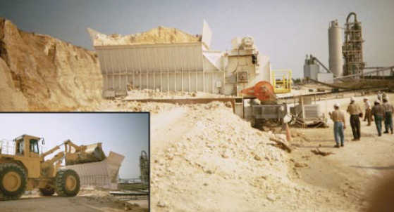
Figure 2.3.2. A primary jaw crusher used in crushing limestone rock at a cement plant quarry.
Jaw Crushers
These crushers are compression machines as already mentioned and come in several forms. The most common types are the single and double toggle designs. These machines are gravity-fed and the material discharge is not mechanically assisted. The reduction ratio of jaw crushers is in the range of 4 to 8.
In a double toggle jaw crusher, which is also known as Blake or Swing type, the jaw is pivoted on an overhead shaft. The swing jaw is put into motion by a double toggle linkage activated by the pitman, which rides on an eccentric shaft. Since the moving jaw is pivoted at the top, its movement is the greatest at the discharge opening and decreases toward the top of the crushing chamber. One end of the crusher frame constitutes the stationary jaw. Most machines of this type currently in use have a crushing angle of about 29° between the swing and stationary jaws (Figure 2.3.3).
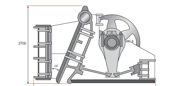
Figure 2.3.3. Double-toggle jaw crusher.
The single toggle type machine, also known as Overhead Eccentric jaw crusher, has a movable jaw with maximum movement at the top of the crushing chamber and minimum at the discharge point (Figure 2.3.4).
The use of jaw crushers as primary or secondary units has been decreasing in cement plants due to the capacity limitation, lack of control of product size (high percentage of oversize), and opera-tional problems, where the limestones are associated with sticky argillaceous materials. The use of jaw crushers seems to be presently restricted to small plants operating with hard and abrasive raw materials. Barring special circumstances, crusher engineers generally recommend that a user consider a jaw crusher for throughputs up to 600 tph (Carter, 1999), although higher capacities are not unknown for jaw crushers.
Materials Preparation and Raw Milling
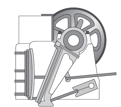
Figure 2.3.4. Single-toggle jaw crusher.
It must be admitted that jaw crushers have shown remarkable staying power since their invention. In recent years indications are strong that the manufacturers of jaw crushers have put in renewed efforts to introduce newer models both for stationary or mobile primary crushing duties. One design area receiving significant attention is crusher toggle angle. Conventional design over the years has made the toggle a key component in protecting the crusher against damage from
“uncrushables,” resulting in a compromise between optimum crusher performance and safety. The crusher manufacturers, therefore, are now looking at methods of securing the machines against damage due to “uncrushables” using hydraulics or other shock-relief systems to protect the toggle.
Some of the recent improvements in jaw crusher performance can be attributed to the advent of computer-aided finite element analysis (FEA), along with improved materials and fabrication methods. It is expected that FEA will eliminate high-stress points in the crusher at the design phase. It is reported that the large crusher manufacturing companies have used this technique for some of their products that are already in the market (Carter, 1999). In some of these new models, different jaw plate profiles can be fitted for different feed materials and the closed side can be adjusted with shim plates to provide a wide range of settings.
The newly designed machines have capacities varying from 45 to 50 tph to 1200 to 1300 tph, and the small crushers have provisions for chassis or track mounting for mobility. The operational experiences in general indicate that the power consumption in primary jaw crushers for medium hard limestones would be as low as 0.21 kwh/t in large crushers and as high as 1.38 kwh/t in small ones (some average comparisons on specific power consumption are shown in Table 3).
Gyratory and Cone Crushers
Gyratory crushers (Figure 2.3.5) are very commonly used for primary size reduction of hard ore. They are also used for secondary and tertiary crushing in the form of standard cone or shorthead crushers that provides a continuous compression action. In the gyratory crusher, a cast conical head or mantle gyrates with an eccentric motion inside a cone-type crushing chamber. At any given point in the cavity, the crushing action comes from a reciprocating compressive motion. However, considering the whole crushing chamber, it turns out to be a continuous compressive action. When used for primary or coarse secondary crushing, these crushers are usually fitted with straight face concaves and a steep sided crushing cavity with a single angle of nip of 26 to 28°. With these types of concaves, the receiving opening is at a maximum. When the maximum capacity and the maximum reduction ratio are required, rather than the maximum feed opening, curved or non-choking concaves are used. The length of the crushing stone is also an important factor as it has significant effect on the capacity and screen analysis of the crushed product. A short stroke may yield evenly crushed product but at a reduced capacity.
The size of the gyratory crushing is designated by the size of the feed opening. Capacities ranging up to 5000 tph are known.
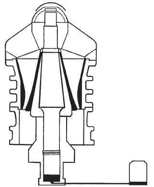
Figure 2.3.5. Primary gyratory crusher.
Cone crushers (Figure 2.3.6) are essentially gyratory crushers, with the mantle and bowl modified for reduction rather than for primary crushing. The mantle is flared to a relatively large diameter skirt at the bottom of the crushing chamber and the bowl is constructed to follow the contour of the mantle. Unlike gyratory crushers, which have an eccentric throw approximately equal to the discharge setting, cone crushers have a much greater throw and higher eccentric speed. These machines have a flatter crushing head than the gyratory type. Cone crushers are available up to capacities of over 1000 tph.
Standard and shorthead machines are used for secondary and tertiary crushing respectively. The principle difference between these machines is the shape of the crushing cavities. While standard secondary cone crushers are normally operated in open circuit, tertiary short head crushers oper-ate in closed circuit with a screen to produce the controlled product size.
In many situations, cone crushers differing in drives and crushing cones are used for intermediate and fine crushing in combination with the Blake-type jaw crusher for primary crushing. Such a multi-stage crushing plant may have an advantage of low wear compared to impactors or hammermill crushers, due to lower differential velocity between material particles and breaker plates. However, the installation cost and complexity of layout for such a multi-stage plant should not be ignored.
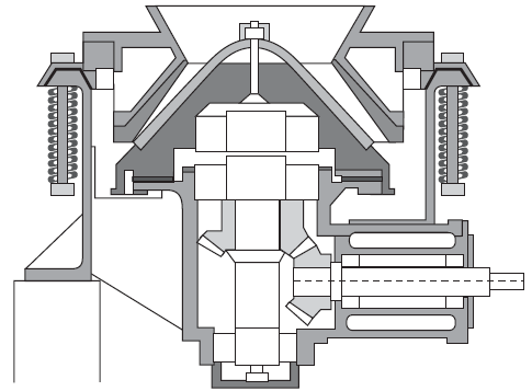
Figure 2.3.6. Secondary cone crusher.
In a comparison between jaw and gyratory crushers, the latter are used more in the cement indus-try for the following reasons:
1. Gyratory crushers have two to three times higher capacity with the same size feed opening and discharge setting.
2. On the basis of energy consumption, the capacity of a gyratory crusher per kwh is 1.3 to 3.6 times higher than that of a jaw crusher on a comparable basis.
3. While idling, gyratory crushers use up to about 30% of full load power and jaw crushers consume 45% to 50%.
Roll Crushers
In principle, roll crushers effect size reduction through the compression mode in the same manner as in jaw or cone crushers. The crushers may either be single (Figure 2.3.7) or double roll (Figure 2.3.8) types. The crushing rolls may be smooth, toothed, riffled, or corrugated on the surface. In the cement industry, toothed roll crushers have generally been in use.
In the roll crushers used in the cement industry, it is the shell diameter and the tooth profile that determine the feed size and nip angle. Capacity is dictated by the actual width of the shell. The peripheral speed of the shell is also an important factor and can vary from 1.4 m/s to 10 m/s, depending on the material type and throughput. In addition, the rolls may operate with differen-tial speeds so that the crushing effect is achieved by radial pressure and tangential forces.
It is often claimed that of all the types of crushers available for primary and secondary crushing of limestone and argillaceous materials, the double roll crusher is the most versatile. It can process materials ranging from a dry dusty type to an extremely sticky variety.
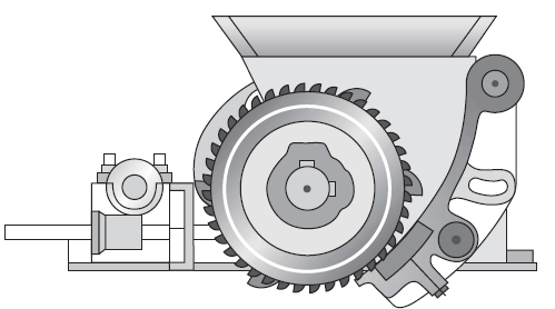
Figure 2.3.7. Single roll crusher.
Figure 2.3.8. Schematic diagram of double roll crusher.
In recent times certain significant improvements have been incorporated in the design. Two identi-cal shaft lines are independently mounted and driven.Each shaft line is supported by a spherical bearing that is grease-lubricated. These bearings are perfectly sealed against dust and water. One shaft line is rigidly mounted, while the other is slide mounted. Adjustment to crusher setting can be made in minutes by mounting the adjustable shaft line toward and away from the fixed shaft line. Tramp metal removal is easy, as the adjustable shaft line is spring-mounted.
The reduction ratio is about 6:1 and the machine can handle limestones with compressive strength up to 1400 kg/cm2 (McCarter, 1996).
Impact Crushers
Unlike the roll, gyratory, and jaw crushers that work on compression, impact crushers operate primarily on the principle of dynamic impact as explained earlier. In impact crushers, there is a free fall of rocks and throwing at high speed against stationary surfaces. The fragmentation of the feed material is largely dependent on velocity and, hence, on the peripheral speed of the rotor. Impact crushers can be broadly typified by as follows:
• Fixed hammer impactors. Single- and double-rotor impactors are designed to handle nonabrasive rocks which are fragmented by the high speed pulverizing action of fixed hammers mounted on a heavy control rotor. For limestones containing free silica not exceed-ing 5% to 7%, impactors turn out to be a good choice for either primary or secondary crush-ing, when a high reduction ratio, high capacity, cubical product, and high properties of fines are desired.
• Hammer mills (crushers). These machines can either be single-rotor or double-rotor type (Figure 2.3.9). In the single-rotor type the rotation is counterclockwise so that the hammers force the material downward. The bottom part of the crusher consists of longitudinal grid bars, and the distance between the bars and the speed at the hammer determine the maximum size of the crushed product. Size reduction is achieved by the impact of swing hammers against the breaker blocks and finally by the crushing action against the grid bars.
Figure 2.3.9. Single-rotor hammer mill.
• A double-hammer crusher with two rotors (Figure 2.3.10), the left-hand unit rotating clock-wise and the right-hand unit counterclockwise, offers the possibility of handling larger feed size, larger output, and higher moisture content in feed material.
• Impact hammer mills. In this variant (Figure 2.3.11), the feed material enters the crusher from the left and is transported toward the hammer rotor by slowly rotating one or two shock-absorbing inlet rollers to avoid jamming and to ensure precise feed control. The hammers rotate clockwise. When they hit the feed material from below, fragments are thrown against the breaker plates and the inside casing, where secondary crushing takes place. The final crushing is performed between the hammers and the outlet grate.
Figure 2.3.10. Double-hammer mill.
Figure 2.3.11. Impact-hammer mill (EV crusher of FLS).
Swing hammer reversible impactors. In these machines, the rock is slammed by the free-swinging hammer against breaker plates arranged circumferentially around the upper part of the chamber and allowed to fall freely from the bottom, as there is no grate arrangement (Figure 2.3.12). Reversibility of the impactor calls for a central feed chute to the crushing chamber.
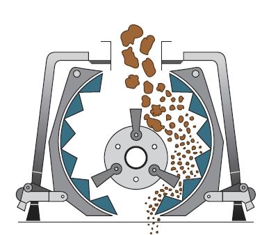
Figure 2.3.12. Reversible-hammer mill (Source: Pennsylvania Crusher Co.).
Hammer crushers and other impact crushers are suitable for crushing limestone and other cement raw materials as long as these are not very abrasive. A larger hammer crusher has a very high reduction ratio. It can be fed materials having a lump size of 1 m and can deliver a product with a maximum size of about 25 mm.
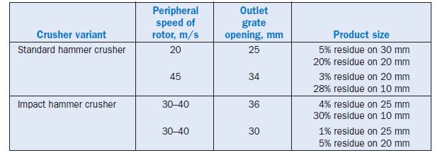
On the other hand, these crushers suffer from a high wear rate of parts and consequently becomes suitable for non-abrasive materials such as limestones with less than 5% free silica. The tentative wear rates of hammers lies in the range of 0.5 to 12 g/t of material treated, but under high speed the wear rates could be higher (4 to 12 g/t). A general idea of the effects of peripheral speed of the rotor and outer grate opening and the product size can be obtained from Table 2.3.1.
It has been reported that a specific model of impact hammer crusher of a renowned machinery manufacturer is capable of crushing 2500 tph with outlet grate and up to 3000 tph without it (F. L. Smidth, 1999).
Table 2.3.1. Effect of Peripheral Speed of Rotor and Outlet Grate Opening on Product Size of Impact Crushers
RECENT INNOVATIONS IN CRUSHER DESIGN
The major thrust of design improvements for crushers has been on equipment reliability. For this purpose, improvements have been achieved in the materials of construction and elimination of high-stress points in existing machine designs. In addition, the objectives of design improvements included – increasing the maximum feed size, raising the upper limit of the feed moisture content, and constructing mobile installations with reduced weight. In the process, a few newer designs of crushers appeared on the market, some of which are illustrated below:
1. Impact crushers as secondary crushers, when the breaker plates are spring-loaded and there are a greater number of impact bars.
2. Reversible hammer mills that can be run in either forward or reverse directions. The advantage of this design is that it can reportedly handle twice the wear that occurs for an ordinary mill.
3. Slugger crusher as patented by the Williams Co., USA (McCormack, 1996) designed with self-cleaning breaker plates to reduce feed material to smaller than 25 cm without any clogging.
`4.Impact crusher-dryer, designed by Krupp Fordertechnik (McCormack, 1996). Depending on design, impact crushers-dryers are capable of crushing feed sizes of up to 1000 mm and mois-ture contents of up to 20%.
5. F.L. Smidth twin-shaft breaker designed to crush soft to medium-hard materials. The configu-ration of breaker teeth may be arranged to meet the specific end-product requirements of different mill systems, including vertical roller mills (F.L. Smidth,1999).
6. Mag’impact crusher of Magotteaux with high productivity and cubical rock products, devel-oped essentially for the construction industry (Magotteaux, 1999). Its relevance for cement raw materials has not been reported.
7. Automated system regulation developed for the secondary cone crushers. The system claims to protect the machine from overload and also to provide control of the crushed product (Heckert, 1999).
Obviously, the above list of design developments is not exhaustive. It only illustrates current trends in meeting customer expectations. One such expectation is having mobile portable crushers, the salient features of which are highlighted below.
Mobile Crushers
It is a normal practice to transport raw materials with a maximum size of 1 m or more from the quarry face to a stationary crushing plant by dumper trucks. For larger quantities, the cheaper transport of belt conveying can be considered only after primary crushing so that the rock is trans-portable by a belt conveyer. To meet this requirement, traveling crushers (Figure 2.3.13) are availble in the market and the viability of installing such crushers is weighed against truck transporta-tion of run-of-mine rock to the stationary primary crushing plant. Whenever decisions are in favor of installing mobile crushers, only lightweight jaw or impact crushers are considered.
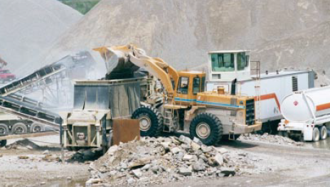
Figure 2.3.13. Mobile crusher installed at a limestone site.
It is often observed that there are very few truly mobile crushers capable of moving from one quarry face to another, because of the fact that support frames, feeders, screens, conveyors, genera-tors, etc. have to be dismantled, disconnected, and reassembled at the new face. Hence, looking at the increasing demand of mobile crushers, there is a deliberate effort on the part of manufacturers to construct lightweight primary crushers with effectively transportable system design. Illustrations may be given of C-series and NW-series portable jaw crushing plants of Nordberg. Another new model, LT 105, of this company is a truck-mounted mobile crusher driven by a 240 HP diesel engine, offering output up to 480 tph (Carter, 1999).
The relevance and advantage of adopting a mobile crusher plant in an aggregate production unit have been reported by Drake (1999). This relates to the experience of installing a Nordberg 1415 Lokstrack system, including the manufacturer’s locolink motorable conveyors. This installation peaked the throughput to 850 tph and assured a constant flow of material with 10% to 20%increase in plant capacity.
PRODUCT FINENESS AND ENERGY REQUIREMENTS IN CRUSHING
It is generally understood that size reduction by crushing consumes less power than comminution by grinding, at least within the boundary of fine crushing as defined earlier.
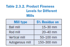
The characteristics of cement raw materials in most cases allow single-stage crushing by impact-type crush-ers. The product fineness is decided depending on the downstream grinding system that would be fed with the crushed material. Depending on the type of the mill, the following levels of product fineness are usually necessary (Table 2.3.2):
Generally, it can be said that cement raw materials should not be crushed finer than is necessary. Thus, following the above guidelines, when vertical roller mills are used for grinding, impact crushers with an output range of 0 to 90 mm (maximum 100 mm) are preferred. When ball mills or roller presses are used in grinding, hammer crushers with an output range of 0 to 25 mm are mostly used.
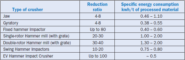
The tentative ranges of specific power consumption of different crusher systems have been mentioned earlier in the context of their constructional features. The data are summarized in Table 2.3.3 for comparison. On the whole, the power consumption is generally estimated to lie within 0.5 to 1 kwh/t of material processed.
Table 2.3.3. Specific Energy Consumption of Different Types of Crushers
Selection of Crusher Type
The correct selection of the crusher type is a prerequisite for economic operation of a cement plant. It is imperative that the characteristics of materials to be crushed are fully understood with respect to crushing strength, hardness, abrasivity, associated rocks, and range of moisture content (McCarter, 1996).
The seasonal variation in moisture content in raw materials as well as differences in the crush-ability of associated rocks and minerals affect the crusher throughput. The size of the feed to the crusher is quite important and often it is advisable to reject oversize feed material before it enters the crusher, rather than overdesign the crusher to accommodate the oversize material.
The achievable reduction ratios vary from crusher to crusher. The higher the reduction ratio, the higher the generation of fines, which is not always desirable. The desired reduction ratio is an important criterion for selecting the type and system of crushing.
On the whole, the characteristics of feed material, desired end product, reliability of the machine, costs per ton of wear parts, power consumption, and simplicity of the operating system are the prime considerations in the selection and design of a crushing plant.
With widely varying raw material characteristics as well as feed and product size requirements, the equipment selection, system design with number of stages, and plant layout call for considerable experience and skill on the part of the designer. Close interaction with the user at the selection and design stages helps to avoid all future surprises.
PREHOMOGENIZATION OF RAW MATERIALS
Basics
In cement production, it is often necessary to prehomogenize the raw materials after secondary crushing, particularly when their chemico-mineralogical composition varies over a wide range. This unit operation is utilized primarily for the main raw materials, viz., the limestone and the aluminosilicate component.
In the prehomogenizing systems, which, according to Hasler and Vollmin (1975), are also known as “blending beds,” the blending effect, H, is generally determined as the ratio between the standard deviation Sin of one significant chemical parameter of the input to a given stockpile and the stan-dard deviation of the same parameter Sout of the output from the same stockpile, as follows:
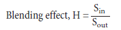
In principle, the homogenization effect as reflected by the reduced standard deviation of the mate-rial composition is achieved by stacking the material in a large number of layers. Theoretically the blending effect is closely linked to the square root of the number of layers reclaimed in cross-section after the formation of material beds.
In this context, it is important to note that normally it is not possible in practice to measure homogenizing effects greater that 1:10, due to the statistical inaccuracies inherent in the represen-tative sampling and analyses of lumpy materials. In practice, however, the blending efficiency of the prehomogenization systems lie within this range.
Process Outline
The prehomogenizing systems have two major operations: 1) storing or stacking and 2) retrieval or reclaiming of materials. That is why the facilities are also often known as “stacker-reclaimer systems,” Depending on their homogenizing capability, two broad categories can be considered for these systems.
Essential Storage Systems With Low Blending Effects
This category consists of systems in which the stockpile is built up by continuous, alternate, or axial stockpiling (Figure 2.3.14a. b. c.). It is also possible to form a pile by depositing material in a single cone from a fixed position. When this conical pile is full, the stacker discharge point moves to a new position and a shell is formed against the surface of the first cone. This process continues in the longitudinal direction of the pile until the formation is complete.
Reclaiming from these stockpiles is done by a Portal scraper, which is a kind of a side reclaimer.
The equipment used in this essential storage systems is relatively inexpensive and the blending effect is low, generally 1:2 to 1:5, since the number of layers simultaneously reclaimed is rather limited (4 to 25).
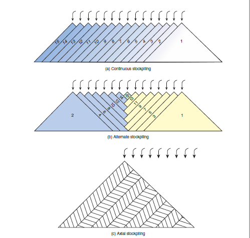
Figure 2.3.14. Different methods of stockpiling.
Essential Blending Systems
This category of prehomogenization system utilizes the Chevron or Windrow method for stockpil-ing. In both these methods of depositing, a large number of layers can be formed in a stockpile.
The Chevron method can be utilized to build up stockpiles of two different geometries: longitudi-nal and circular (Berthhold, 1979). In building up a traditional longitudinal stockpile by the Chevron method, the stacker moves to and fro over the central line (Figure 2.3.15). It is a discon-tinuous technique by which stacking takes place in one half portion of the stockpile, while the other half portion is reclaimed. In the circular stockpile build-up by the Chevron method, there is a continuous round base with stacking at one end and reclaiming at another. Stacking takes place in a fan-shaped arc, typically extending over 120°. With each sweeping movement corresponding to two layers of material, the whole sector moves approximately 12 mm.
The circular stockpiles are particularly recommended for optimum utilization of space and for meeting the requirement of high continuous homogenizing effect, but the storage capacity cannot be extended and the chemical composition of the full pile cannot be changed without emptying the whole yard.
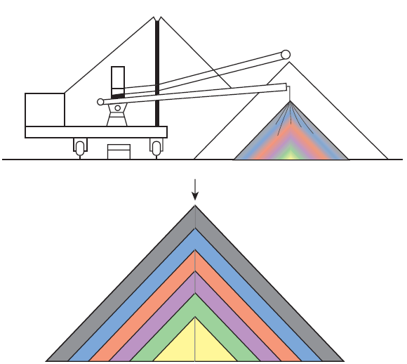
Figure 2.3.15. Roof-type stockpiling (chevron method) with stacker boom that can be lowered and lifted.
The Chevron method causes segregation of the material with fine particles in the central part of the pile, and coarse particles on the surface and at the bottom of the pile. To ensure proper blend-ing, a Chevron pile must therefore be reclaimed from the pile end in the longitudinal type, work-ing across the entire cross-section.
In the Windrow method, material is deposited from a number of positions across the full width of the pile (Figure 2.3.16). This method, essentially followed to build up longitudinal stockpiles, prevents segregation and is preferred in cases where the reclaimer operates in one part of the pile cross-section at a time or where segregation may create situations of total unacceptability. Apart from segregation, the clogging tendency of materials is also an important consideration when deciding on a prehomogenization system.
The reclaimer is usually equipped with a constant speed motor when the reclaimed material is carried by belt conveyors to large-volume intermediate storage bins. The reclaimer can also operate in a direct mode, feeding the mill without any intermediate storage, when the reclaimer is equipped with speed regulated motors and an integrated belt weigher.
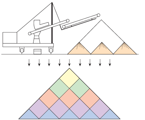
Figure 2.3.16. Layer-type stockpiling (windrow method) with stacker rigid boom and tele-scopic belt.
DEVELOPMENTS IN HARDWARE SYSTEMS
For building up the stockpiles, different types of stackers such as rigid or slewing, stationary or traveling type, are available for reclaiming bulk materials from the stockpile. The versatile portal type scraper reclaimer is often used. When a fair level of prehomogenization is required, preference is given to a bridge-type scraper reclaimer. A circular storage system is generally provided with a cantilever scraper reclaimer, while a circular prehomogenizing system operates with a bridge-type scraper reclaimer.
The prehomogenizing systems can be installed in open-air or covered buildings. The covered installation is preferred from the considerations of environmental protection and avoidance of contamination, although such installations become more expensive.
Circular stockpiles with bridge scraper reclaimers can be considered an innovation that is still being perfected. Depending on the purpose of the system, four different types of blending beds are considered which are shown in Figure 2.3.17 (Fischer, 1999). In Figure 2.3.17a, there are two sepa-rate stockpiles, each built by the Chevron method, as in the case of a longitudinal system. The stacker A is engaged in building up the first pile, while the bridge-type scraper reclaimer is reclaiming from the second pile. For better space utilization, it may be advantageous to leave some clear gap between the two piles. The reclaimer then operates in two directions and therefore requires two harrows – one for each direction of rotation of the bridge and subsequent reclama-tion. In author’s opinion, this approach may not help achieve more constant average material properties than in longitudinal piles because of the circular pile end cone effects. More consistency with the longitudinal blending bed is found in the overlapping Chevron piles as shown in Figure 2.3.17b. A simpler method of stacking is embodied in the stockpile built on the cone shell princi-ple, described earlier, as shown in Figure 2.3.17c. The stacker boom does not need buffing move-ment and advances in small steps in only one direction. This technique also has the snag of the reclaimer harrow slicing through only a limited number of cone shell layers at any given time, thereby affecting the blending effect. It seems to the author that the “Chevcon” method as shown in Figure 2.3.17d is characterized by excellent blending effect and considerable operational adapt-ability. The stacker travels continuously to and fro in the circumferential direction of the pile; at each reversal of direction the stacker is moved forward by a certain distance. Many plants have claimed success with this technique.
Sampling, Material Analysis, and Application Software
It is evident from the previous discussion that the aim of a preblending bed is to store the raw material in such a way that the pile at any position will have a chemical composition with a value as near as possible to the chemical composition required by the plant. The homogenization of the stockpile will not be achieved if the dosing of materials, as well as the real chemical composition of the pile, is not monitored and controlled.
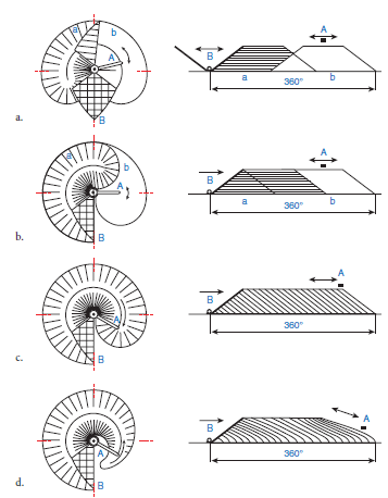
Figure 2.3.17. Different stockpiling methods in circular beds. The plan views are on the left and the longitudinal sections parallel to the center line are shown unrolled on the right.
An important step is the sampling of material during the formation of stockpiles. Ideally each layer of the heap should be analyzed accurately, which requires a complicated sampling installation. In traditional sampling stations for crushed limestone, typically about 2% of the material flow is diverted as a spot sample at a given point of time. The accumulated sample for a given period of time is subjected to stepwise size reduction. For wet materials, infrared dryers are provided. Ultimately duplicate analytical samples of 250 g/h each are generated through the system and analyzed by on-line or off-line x-ray fluorescence spectrometers.
A more convenient system has subsequently emerged with the development of the on-line cross-belt gamma ray analyzer for bulk materials (Tschudin, 1995; Woodward, 1997; and Sucre, 1998). This system is based on the identification and quantification of constituents by recognizing the gamma ray emitted by the material when it is activated by neutrons emitted by a source
Software Development for Preblending
Various attempts have been made during the last 15 years or so to develop appropriate software for preblending. The initial versions were based primarily on oxide composition and multiple linear regression analysis to determine the tonnage of each source material required to satisfy the oxide targets for the completed stockpile.
Later versions have attempted to set quality control parameters as quality targets for the stockpile. The optimization algorithm was similar to linear programming rather than linear regression.
The above approaches have led to the development of such proprietary softwares as MIXOPT, PREBOS, and Smart-Stack (Woodward, 1997; and Sucre, 1998) which, when coupled with appro-priate bulk material analytical facilities, can build up stockpiles of targeted composition.
PREBOS reportedly can achieve the blending of raw materials either automatically or with opera-tor assistance. It can also be used in longitudinal or circular stockpiles. Smart-Stack controls the stacker-reclaimer system. PREBOS and Smart-Stack are linked to interact with each other.
Based on the experience gained from the use of analyzers and application software, certain benefits have been reported.
One of the advantages pertains specifically to the circular stockpiles. It is known that in the longi-tudinal stockpiles the deviations from the target chemistry can be corrected before the stockpile is completed. The continuously operating circular stacker-reclaimers offer little opportunity to recover from compositional deviations because these stockpiles do not have clearly defined batch boundaries. This limitation of circular stockpiles can only be overcome if the chemistry of the material being fed to the pile does not vary significantly from the target for any significant length of time. For this reason, circular stockpiles need analyzers and operating software even more than the longitudinal piles.
Another benefit of an on-line bulk analyzer and application software is the possibility of doing away with separate stockpiles of limestones and argillaceous materials. If an analyzer is used to control the limestone/clay ratio, varying the clay fraction in response to the variations in limestone quality coming over to the stockpile, then a single composite stacker-reclaimer may suffice. It is obvious that the advent of on-line bulk material analyzers and accompanying software has begun to change the approach toward quality control in cement plants.
GRINDING OPERATION AND MILLING SYSTEMS
Technology Evolution
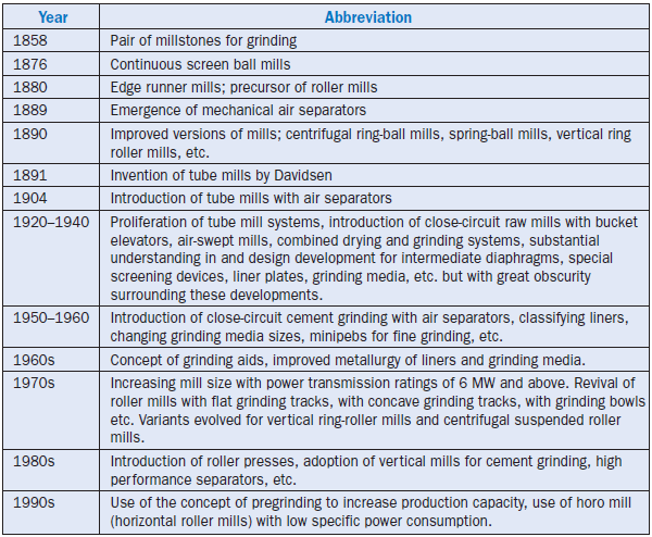
As indicated earlier, the crushed and preblended raw materials are further processed into a fine raw mix by dry or wet grinding. With escalating energy costs and progressive obsolescence of the wet process of manufacturing, dry grinding of raw materials is practiced most extensively. Within the ambit of dry comminution, further advances have essentially been dictated by the continuing pres-sure for energy efficiency. The initial endeavor was to modernize the ball mills that played a predominant role for decades in cement plant grinding operations. Later more innovative and effi-cient systems like roller mills and high pressure hydraulic roller presses were adopted. The techno-logical milestones in the chain of evolution of the grinding systems can perhaps be reconstructed as given in Table 2.3.4 (Chatterjee, 1991).
Table 2.3.4. Technological Milestones in the Evolution of Milling Systems
Ball Mill
The majority of grinding in the world is performed with the help of ball mills (Figure 2.3.18). The material to be ground passes through the rotating cylinders, and grinding takes place by the impact of and attrition from the grinding balls tumbling inside the cylinder. In early days a ball mill was used in conjunction with a tube mill. The ball mill was short with a large diameter (L/D = 0.5) and very large size grinding media. The mill was fitted with peripheral screens that passed coarsely ground material to the tube mill, which was long with a smaller diameter (L/D= 5.0). Such a system was necessary then, as the feed to the ball mill was fairly large in size. Since later the mill feed size could be brought down to 25 mm or so, large balls were no longer necessary, and the functions of the ball and tube mills were combined into a “compound mill.” This was divided into “chambers” by perforated diaphragms permitting the passage of materials, but not of the balls.
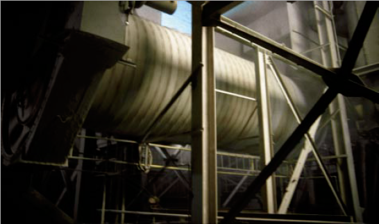
Figure 2.3.18. Ball mill in operation at a cement plant.
The mill shell was protected against wear by liner plates bolted to it. A more recent development has been the introduction of “classifying liners” designed to aid the small balls in migrating toward the discharge end and the bigger ones toward the feed end.
In yesteryears, the classical mills for open circuit grinding were divided into three chambers with varying ball charges. With the classifying liners it became possible to have two-chamber ball mills for complete grinding.
In the subsequent period, ball mills known as “air-swept tube mill” and “tube mill with bucket elevators” were developed to carry out both drying and grinding of moist materials. They worked in close-circuit, the object of which was to remove the material from the mill as soon as it had reached the required fineness in order to prevent it from blanketing the grinding action or being ground unnecessarily fine.
Ball mills have undergone considerable evolution in the last three or four decades. The trends are reflected in increasing mill size, use of high efficiency separators, adoption of new designs of mill internals, application of innovative control systems, and adoption of hybrid plants. While the concept of hybrid plants will be treated later in the section, some of the other significant develop-ments of ball mills are highlighted below.
Developments in the Design of Ball Mill Internals
Efficiency and output of the ball mills primarily depend on the optimum utilization of ball charge energy for coarse and fine grinding. The most important developments in this regard have been the optimum design of mill internals to impart maximum angular lift and correct trajectory to the ball charge. This imparts powerful crushing in the first chamber and perfect ball classification for efficient grinding in the second compartment of the mill to ensure the desired retention time of the material in the mill. The developments specifically involved the adoption of improved metal-lurgy in the manufacture of grinding media and liners, innovative design of liner geometry, and flow control arrangements of the mill diaphragms.
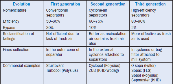
High-performance Separators
Based on the stage of development, separators have been classified as first, second, and third gener-ation. In first-generation separators, the air currents were generated by a fan within the body of the separator. They were, therefore, of internal air circulation type. In second-generation separa-tors, air was supplied from an external fan and the distribution disc was driven separately. The simultaneous effects of a separate air current and separate centrifugal movement resulted in better classification. In third-generation separators, the air flow is better guided and controlled. The clas-sification zone is made into a compact zone of a rotating cage. In this type of separators, all the basic principles of good classification are satisfied, making them “High-Efficiency Separators.” The main distinctive features of these three generations of separators are given in Table 2.3.5.
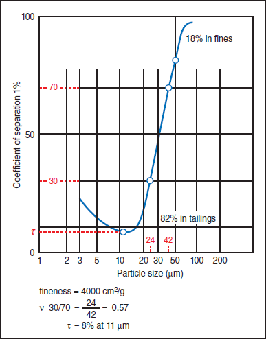
An efficient way of describing the classification process over the entire range of particle sizes is by plotting the particle size against its recovery in coarse tailings. These curves are known as “Grade Efficiency Curves” or “Tromp Curves” (Figure 2.3.19). They are calculated from the percentages by weight of individual fractions (the more fractions, the greater the accuracy) of the three separator streams: feed material, tailings, and fines. The result of the calculation is a distribution figure (% by weight) for a particular fraction. The function shown in the diagram, viz., the partition ratio (%) as the function of particle size (µm) is obtained from a number of points. Finally, the curve obtained states the percentage by weight of each individual particle size of the separator feed material that passes into tailings and into the finished product. The percentage in the finished product can be read off above the curve and those in the tailings below the curve. The steepness of the curve and its location with respect to the two coordinates in the diagram are important in assessing the selectivity of the separator. The “Kappa” value as the ratio of the percentage of two particle sizes has been introduced as a measure of the steepness of the Tromp curve. The steeper it is, the more efficient the separator. The lowest point (minimum) of the Tromp curve is referred to as “Tau.” The separator achieves its greatest separating efficiency for the particle size associated with this partition ratio. The flatter the left hand branch and the lower the value, the greater the selectivity of the separator in the finer range of particle size. In addition to Tau, the location of the Tromp curve is also determined by d50. The small the value of d50, the finer the range of separator fines.
Table 2.3.5. Distinctive Features of Separators of Different Designs
The above concepts, in addition to the traditional feature of circulating load in close-circuit mills, have helped in designing the high-efficiency separators.
The benefits that accrue from such separators in raw grinding are as follows:
1. The narrow particle size distribution and lower residues on 200 microns improve the burn-ability of raw mix. This results in better quality clinker and lower fuel consumption.
2. Alternatively, the materials can be ground to the same residue on 200 microns while having higher residues on 90 microns. In this case, while the burnability remains unchanged, higher raw mill output and lower power consumption can be achieved.
3. With reduced circulation of fines, grinding efficiency is improved.
Vertical Roller Mills and Variants
In recent years, the use of ball mills and, more particularly, of air-swept ball mill systems, is being overtaken by vertical roller mills. This is essentially due to the fact that with increasing diameter and capacity of ball mills there is a decrease in their specific gas volume, when the permissible gas veloc-ity in the mills is maintained (Figure 2.3.20). Although this problem was to some extent minimized by introducing sliding-shoe bearings in place of trunnion bearings in ball mills of diameter exceed-ing 4 m, as the latter restricted the gas flow through the mills, a well-designed ball mill can today handle moisture level of 12% or so. On the other hand, a vertical roller mill can accept raw materials containing up to 20% moisture. This advantage of roller mills is in addition to their lower power consumption and smaller dimensions compared to ball mills of comparable throughput.
The vertical roller mills of today developed from the edge-runner mills used before the advent of tube mills. The material is ground on a pan or table rotating about a vertical axis onto which rollers are pressed down by spring or hydraulic pressure. These mills are air-swept, using hot gas for drying while grinding, with a classifier incorporated in an airtight casing within the body of the machine. The table is driven through the trains of gears below it. In addition to the vertical roller mills, there are two other roller grinding processes known as roller presses and ring roller mills.
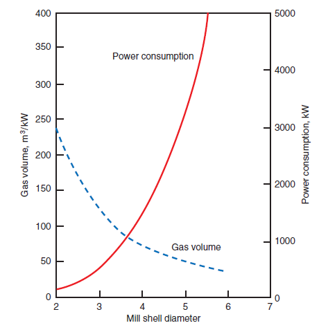
Figure 2.3.20. Gas volume and power consumption of tube mills.
The operating principles of vertical roller mills, roller presses, and ring roller mills are schemati-cally shown in Figure 2.3.21 and the basic features of the three systems are compared in Table 2.3.6 (Brunkick and Schafer, 1999).
Table 2.3.6. Comparison of Roller Grinding Systems
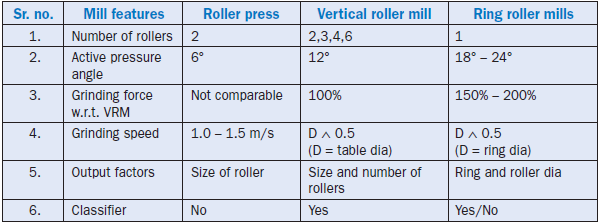
Figure 2.3.21. Different comminution systems based on rolling action.
Advances in Vertical Roller Mills
Vertical roller mills are now available from almost all major cement machinery manufacturers, but they differ in the design of the grinding bowl, rings, and rollers (Figure 2.3.22). The external mate-rial recirculation for vertical roller mills was first introduced in the early 80’s as a means of saving power. Since then, numerous developments have been incorporated into the design of the mill internals, such as variable-area louvre rings and high-efficiency classifiers. These developments have resulted in lower pressure losses, improved preclassification of coarse fractions, and optimum material conveying velocities. Consequently, the potential power savings from the external material recirculation is not as high in today’s vertical roller mills.
Figure 2.3.22. Roller mills with conventional classifiers.
In addition to the above developments, the service life of the grinding elements have been substan-tially increased in recent years as a result of improvements in wear-resistant construction materi-als. Depending on the abrasiveness of raw material, values ranging from 6000 to 16,000 hours are reported (Mälzig and Their, 1987). After some initial difficulties the compact bevel-planetary gear has made headway against the conventional bevel-spur gear drive.
It is well known that in the cement industry, in order to derive the benefit of the scale of operation, there is a trend toward larger production units. The effect of this trend on the manufacture of vertical roller mills is shown in Figure 2.3.23 (Jung, 1999), which indicates that mills having capacities in the range of 400 to 600 tph with drive ratings between 4000 to 5000 kW have already been produced; the operating experience of running vertical roller mills with output ranges of 630 to 650 tph has been reported by Becker (1995). The future expectation is further capacity increase to 700 tph and beyond. Success in designing and manufacturing large vertical roller mills has essen-tially been due to reliable dimensioning of the mechanical components and the adoption of finite element analysis for certain highly stressed critical components.

Figure 2.3.23. Development of throughput capacity and drive rating in vertical roller mills for producing raw meal.
ities in the range of 400 to 600 tph with drive ratings between 4000 to 5000 kW have already been produced; the operating experience of running vertical roller mills with output ranges of 630 to 650 tph has been reported by Becker (1995). The future expectation is further capacity increase to 700 tph and beyond. Success in designing and manufacturing large vertical roller mills has essen-tially been due to reliable dimensioning of the mechanical components and the adoption of finite element analysis for certain highly stressed critical components.
For raw meal preparation, the success of a roller mill with four grinding rollers and a high-efficiency separator at the Bosenberg cement works in Germany has recently been announced (Schneider, 1999). The roller mill with a grinding table of 2.0 m and four externally mounted 1.0 m diameter x 0.4 grinding rollers, designed for a nominal throughput of 55 tph raw meal of less than 12% residue on 90 mm reached a throughput of 68 tph with specific power consumption of 11.45 kWh/t.
High-Efficiency Separators in Roller Mills
The concept of high-efficiency separators can be successfully realized in roller mills as effectively as in other milling systems. In roller mills with conventional separators, the following problems are encountered (Onuma and Ito, 1995):
1. Accumulation of fine particles in the mill prevents the formation of a good material bed on the table and consequently brings down the grinding efficiency.
2. Accumulation of fine particles in mill-separator circuits causes an increase in pressure loss in the circuit.
3. Incomplete separation of coarser particles often causes poor burnability of raw meal.
All of these problems have successfully been solved through the introduction of high-efficiency separators, different models of which are now available to the industry.
The majority of these models have variable-speed cage-type rotor with adjustable guide vane arrangements as shown in (Figure 2.3.24a, b) for a variant of FLS Sepax design (Wehr, 1999) and a model like Loesche LSKS (Brundick and Schäfer, 1998). Other commercial types like Sepol RM
Figure 2.3.24. Some examples of high efficiency separators of vertical roller mills.
(Schneider, 1999) or OKS separators (Birch and Keefe, 1998) are of comparable designs, differing in specific details.
It should be borne in mind that advances in vertical roller mills have been dictated more by the adoption of this milling system for clinker and slag grinding as well as production of pozzolanic blended cements. Apart from design improvements in the classifiers, the concept of speed reduc-tion to minimize vibration and the use of roller pairs with a master-slave arrangement (Brundick and Schäfer, 1998) have been implemented more from the angle of effectiveness of cement grind-ing than the preparation of raw meal.
However, thermal stressing in vertical roller mills when drying and grinding very moist materials has led to the development of proper methods for designing and dimensioning the components
(Jung, 1998; Brundick, 1998). When large volumes of water have to be evaporated, the gas tempera-tures at the mill inlet can sometimes be as high as 600°C. The mill components exposed to the hot gas flow, therefore, either have to be made to withstand such high temperatures or protected from their effects. Further, when mills are started up from ambient conditions, care should be taken not to exceed the calculated temperature gradient on which the mill components have been dimen-sioned. With these developments of design and operation, vertical roller mills now have been oper-ated with raw materials containing more than 20% moisture.
With the ever-growing popularity of roller mills, the reliability of wearing parts such as roller tires and table liners has become more critical than ever. In order to avoid roller tire breakages, a new composite material known as “Duocast” has been developed (Leclercq, 1997). The new material consists of high chromium inserts embedded in a ductile iron base. It is claimed that a roller tire produced by this method shows higher mechanical reliability and improved service life by a factor of more than 2. This technology reportedly has been tried in vertical roller mills of different designs of different manufacturers.
LV Technology for VRM
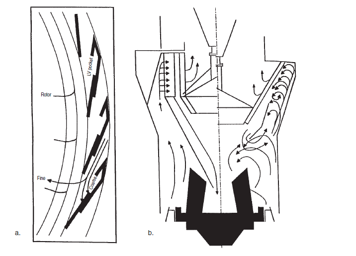
One of the recent developments that demands specific mention in the context of the performance optimization of vertical roller mills is LV Technology (1999), which is adaptable to mills of differ-ent design and addresses three key areas:
1. The separator
2. The air velocity through the mill
3. The air nozzle ring and air guide cone
The separator of LV design differs from others in the design of individual louvres, the number of louvres, the distance from louvre tip to rotor, and the air velocity between the louvres (Figure 2.3.25a, b). It can be adapted to the existing separator housing and separator rotor. The LV tech-nology has, in addition, addressed the need for higher air velocity and acceleration by redesigning
Figure 2.3.25. Basic concepts of the LV classifier system.
the separator reject cone and other mill internals. In most cases a mill upgrade project will include modification of the air nozzle ring and the air guide cone. It is claimed that more than 30 opti-mization projects have been launched since the first modification was taken up by LV in 1998. The upgraded mills have shown a 15% to 20% increase in output and power savings of 1.7-4.2 kwh per ton of raw meal.
Hydraulic Roller Presses
The basic principle of high-pressure grinding with the help of roller presses has already been shown in Figure 2.3.21. The material to be ground is compressed in a gap between two counter-rotating grinding rolls with circumferential speed of about 1.0 to 1.8 m/s to form compacted cake with a volumetric proportion of solids of over 40%. Depending on the comminution behavior of the material and the pressures applied, this can contain up to about 40% fines (< 90 µm) as reported by Conroy and Wüster (1986). The fines are obtained by disagglomeration of the compacted cake, the residual part of which consists of incipient cracks and weak points that greatly reduce the energy consumption in further grinding.
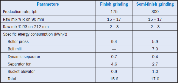
Roller presses are now used with ball mills in both existing and new plants. Such systems, without a downstream ball mill, are also used for fine grinding of limestone and other raw materials. Some statistics regarding the application of this system to the grinding of different kinds of materials had been collated in 1993 (Figure 2.3.26), which showed that, even then, approximately 20% of supplies made by the German manufacturers was geared toward raw meal preparation (Ellerbrock, 1995). The use has increased substantially in the subsequent period.
A few illustrative general layouts for roller presses with or without ball mill circuits are shown in Figure 2.3.27a-d. The configuration given in Figure 2.3.27a is used for grinding raw materials and cement. In this case, the proportion of fines generated in the roll presses is small and consequently it is possible to achieve an increase in throughput of about 20% and energy savings of about 7% to 15%.
Figure 2.3.26. Material-wise proliferation of roller presses in early 1990s.
The arrangement shown in Figure 2.3.27b is intended for using the roller press as a fine or finish mill. The compacted cake is broken up in a downstream disagglomerator and the fines are sepa-rated in a classifier. A hammer mill or a vertical impact mill can be used as a disagglomerator. This kind of system can achieve an energy saving of up to or more than 50% when compared with ball mill systems. Finish grinding of this type with a roller press has been successfully used in the cement industry for grinding raw meal, blast furnace slag, and quicklime.
A “hybrid grinding” plant is shown in Figure 2.3.27c, while the configuration shown in Figure 2.3.27d is known as “semi-finish grinding.” The hybrid grinding scheme involves a combination of pregrinding and finish grinding in the roll presses, while in the semi-finish grinding mode the pregrinding and secondary grinding are separate. Both of these configurations are primarily used in cement grinding and hence not discussed in further detail here.
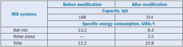
In the early 1990’s, a specific case study was reported involving the modification of a ball mill with a roller press as shown in Figure 2.3.28 (Brugan, 1991). The results of the modified system are given in Table 2.3.7.
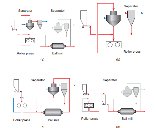
Figure 2.3.27. Different configurations of grinding plants with roller presses.
(a) Pre-grinding mode of the roller press
(b) Finish grinding mode of the roller press
(c) Combined grinding mode of the roller press with both pre-and finish grinding
(d) Semi-finish grinding mode of the roller press
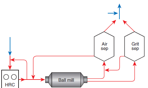
Figure 2.3.28. Configuration of a grinding plant involving a roller press (HRC) at a factory in the United States.
Table 2.3.7. Comparison of a Ball Mill System Modification with a Roller Press
Adaptation of Separators for Roller Presses
High-efficiency dynamic separators, so effectively used with ball or vertical roller mills, have apparently shown very high wear when used in roller press circuits as both the broken agglomer-ates as well as individual particles are extremely abrasive because of very sharp edges and high density of pressed materials. Further, the separators for roller presses need to perform two func-tions – one of deagglomeration and another of separation. Taking into account these require-ments, there have been certain recent developments, one of which is the design of a static
V-separator shown in Figure 2.3.29 (Schultz and Lube, 1997). In this separator, the material to be separated flows like a cascade over a series of steps through which the separating air is routed. The latter removes the fines from the cascading flow of materials and takes them over a parallel series of ascending separating channels to the fines outlet. By regulating the separating air, the plant operator can to a certain extent influence the particle size distribution and the flow rate of rejects and fines. Some amount of disintegration of agglomerates can also take place when they impinge on the steps.
Figure 2.3.29. Schematic diagram of a V-separator.
It is claimed that the roller press operation can be significantly stabilized because the V-separator can remove most of the superfine fraction from the roller press circuit. The removal of this superfine fraction reduces the wear of the roller press as well as of the downstream machines.
A specific case study of a plant having a grinder facility consisting of a roller press, V-separator, ball mill, and dynamic separator reveals the success of a system of this kind (Schultz and Lube, 1997).
The above system had the flexibility of operating both in semi-finish or finish grinding, depending on the inclusion or exclusion of the ball mill from the circuit. The raw materials ground included limestone (92% to 96%), laterite (0% to 3%), and bauxite (0% to 5%). The feed size was 85% pass-ing 35 mm with a moisture content of approximately 3.5%. The Bond’s work index for the feed was 16.0 kwh/t. The operational data of the mill system are given in Table 2.3.8.
Table 2.3.8. Typical Operational Data of a Plant Utilizing a Roller Press with V-Separator with or without Ball Mill with Dynamic Separator
It was seen in this system that the V-separator rejects had a size of not less than 1.0 mm, which ensured steady operation of the roller press. The fines removed in the V-separator were entrained in the air current to the dynamic separator, where rejects and fines of the desired size were sepa-rated. The rejects were fed back to the roller press.
When operated in the finish-grinding mode, the V-separator was used for deagglomerating, drying, and separating the product discharged from the roller press. The kiln gases were used for drying. The inventors of the V-separator are quite hopeful that it will successfully proliferate in the industry.
Two-Stage Sepax Separator
This is a separator system consisting of two classifying sub-units – one for coarse and another for fine separation. Further, it has a built-in disagglomerator of the low-speed vertical impact type at the top of the grit separator (Buzzi, 1995). The main features of the two-stage Sepax separator, compared to conventional separator systems, are the heavily wear-protected grit separator and a high-efficiency top separator module for the low cut size. As the separation air is common for the two separators, the total fines for semi-finish systems consist normally of at least 25% to 50% of particles directly separated from the roller-pressed material and the remaining part of the particles separated from the material ground in the ball mill.
The flowsheet for the two-stage Sepax separator system is shown in Figure 2.3.30, in which the material flow for both the semi-finish and finish grinding modes has been indicated. It has been claimed that the separator system is very effective for both modes. However, the system has been tested more for its applicability in cement grinding.
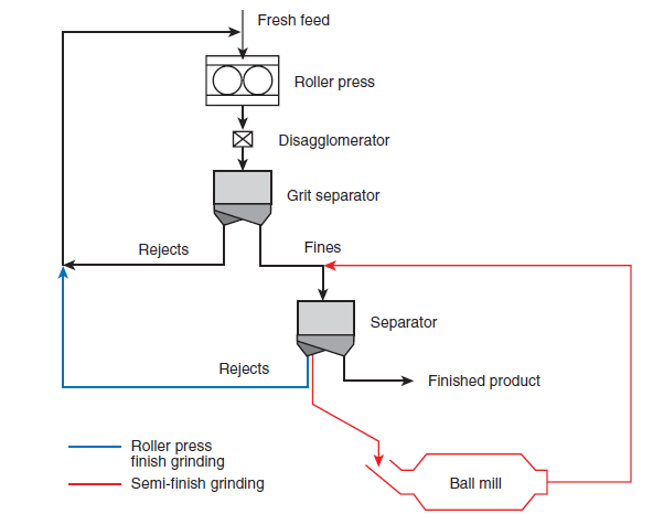
Figure 2.3.30. Configuration of a milling system involving a roller press, a ball mill, and a two-stage Sepax separator.
Improvements in Operational Reliability of Roller Presses
It should be emphasized that the ultimate economy of installing the roller presses depends on the plant availability and its maintenance cost. In the initial years the general experience of operating the roller presses showed that the part of the machines most vulnerable to damage were the roller surfaces. The main aim of continued design development has been to achieve higher operational reliability of the roller surfaces. The solutions found so far are the following:
1. Two-piece grinding roller consisting of a shaft with shrunk-on tire with a welded hard layer as armor (Figure 2.3.31a). This design is often rated as a proven method of construction for the rollers for the usual application.
2. The composite material build-up, in which one or more intermediate layers are welded onto the roller body as buffer layers and a wear-resistant hard-layer is welded on top (Figure 2.3.31b). The welded armor is usually more economical than other wear protection designs.
3. Using wearing parts made of chilled cast material, which are formed as tires or segments chiefly for grinding highly abrasive materials.
4. Wear protection by inclusions of material between a pattern of studs made of hard metal alloy on the roller surface (Figure 2.3.31c). Operating experience indicates that this studded armor-ing is suitable for all materials, both wet and dry.
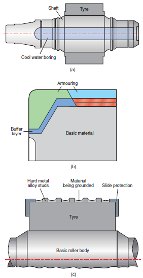
Figure 2.3.31. Armouring of rollers.
(a) Two-piece roller consisting of a shaft with shrunk-on tyre
(b) Welded protection
(c) Studded armouring
All in all, the design of roller press systems sporadically has incorporated a large number of advances as illustrated above. Consequently, the systems have turned out to be more reliable and efficient resulting in higher levels of acceptance in the industry.
Horizontal Roller Mills
It is interesting to note that in the 1990’s, FCB of France and Fratelli Buzzi S.P.A of Italy developed a new milling system that embodied the reliability of a ball mill, the energy efficiency of a roller press, and the flexibility of a vertical roller mill in one machine. It was developed on the basis of a ring-roller mill and took 20 months of planning, design, pilot tests, and construction to get the new mill installed under the tradename “Horomill” with a capacity of 25 tph and drive rating of 500 kW (Buzzi, 1995). Although the mill was originally designated for cement production, the flex-ible layout allowed the grinding tests to be carried out for raw materials and coal as well.
In an industrially operating Horomill, grinding takes place in a rotating shell (say, 3800 mm diam-eter in a given instance) at a rotation speed of 38 rpm actuated by a 2500 kW motor. Shoe bearings and girth gear are all enclosed in a large oil casing surrounding the machine. Inside the shell is a 1600 mm roller, which rotates on two roller bearings with the grinding force applied by two hydraulic cylinders. The feed enters from one side and the ground product discharges from the other side onto a rubber belt bucket elevator at a rate of 900 tph at 110 kW.
Due to the rotational speed, the material is centrifugally held against the shell. It is removed from the shell by a scraper and the material then falls onto an inclined plate, which in turn transports it toward the outlet. The forward displacement is at a shallow angle and therefore the same material can be pressed many times before it exits the mill. The system is provided with a dynamic separator.
A schematic diagram of the basic operating principles is given in Figure 2.3.32 (Fouchardiere, 1999). The installation made at a Turkish plant has provided more than a year’s experience of operation in cement grinding and has shown specific energy consumption of 20.07 kWh/t with mill output of 147 tph of cement, 17% lower and 13% higher than the original targets respectively. No significant wear on the shell liners was reported but the roller surface required replenishment by welding electrodes every 2000 hours. Other maintenance problems, including the relatively high temperature of roller bearings, have been manageable within normal practices.
It is claimed that when compared with ball mills, the Horomills may offer energy savings of 35% to 40% for cement and up to 50% for raw materials. The investigations carried out so far have shown that a Horomill is basically capable of producing a raw meal of good quality. The movement of the
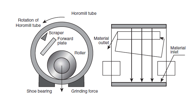
Figure 2.3.32. Grinding mechanism of a Horomill.
material in the mill is not affected by the material moisture, although some loss in grinding effi-ciency was observed when the fresh material at the mill inlet had moisture of more than 6-8%. The Horomill used as a raw mill is claimed to combine the effectiveness of the vertical roller mill and the roller press with a very low pressure drop in the circuit. It is also expected to offer some advan-tage in handling raw materials containing a higher percentage of quartz in comparison to vertical roller mills (Buzzi, 1997).
The development and industrial introduction of Horomills should be followed with interest by cement manufacturers because of the mill’s simple functioning, its stable mode of operating, and its potential to save energy.
HOMOGENIZATION OF RAW MEAL
Basic Methods
The homogenization of raw meal prior to the calcination process has always been a very important step in the production of clinker. It is widely known that there are four methods of raw meal homogenization utilized in the cement industry. The first and the traditional one is the slurry mixing practiced in the wet-process plants; other methods are adopted in dry process plants and include mechanical systems, pneumatic systems, and gravity systems.
In slurry homogenization, the mill slurry is transported to a slurry silo, the average composition of which is tracked with the help of chemical analysis of spot samples. When the silo is about two-thirds full, the slurry is homogenized with compressed air. The slurry from the silos is sent to a basin and further homogenized with the help of mechanical, pneumatic, or pneunomechanical
arrangements before entering the kiln. Experience shows that a slurry basin works as the ideal blender.
The mechanical system consists of multiple storage silos, each of which is provided with regulated withdrawal facilities. Blending is achieved by an orderly withdrawal of material at variable rates from all silos. While this type of mixing consumes lower power, the system requires a great deal of material handling that increases power consumption. In addition, the required of number of silos is obviously more than in other systems. As a result of these shortcomings, this kind of homoge-nization system is not in wide use in the cement industry.
The most common homogenization system used over the past several decades is the pneumatic unit based on the air fluidization method. Air introduced through a permeable medium in the silo bottom causes the raw meal to behave almost like a fluid. This agitational method is known to provide high blending efficiency for dry material. But at the same time this method is the highest consumer of power in relative terms.
The gravity approach to homogenization has been conceived only with the compulsion of achiev-ing reduced power consumption. This is in many ways comparable to the mechanical system. While the mechanical system utilizes multiple silos, the gravity method can work with even one silo but with multiple discharge points operating on a time cycle.
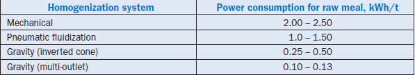
The power consumption levels generally recorded for the above dry blending methods are quite variable, as shown in Table 9 (Bartholomew, 1995); the table shows two types of gravity systems. The inverted cone silo refers to the type utilizing a homogenizing chamber within the central cone. The multi-outlet silo refers to multiple discharge points located above the silo bottom. The differ-ences in these two designs reflect on power consumption as shown in Table 2.3.9.
The pneumatic and gravity systems of homogenization are dealt with further in the following sections with reference to recent advances.
Table 2.3.9. Power Consumption Levels of Different Dry Homogenization Systems
Pneumatic Systems
The pneumatic systems have been traditionally classified as discontinuous and continuous types. The discontinuous types are based on either batch homogenizing or funnel-flow principles, while the continuous ones rely on chamber mixing or cascading of material. A relatively new CF type
(continuous flow) homogenization system recently was added by F.L. Smidth.
Because of the high capital cost, the intermittent homogenization systems are used only in special cases, where the variations in chemical composition are to be kept very small – even lower than that attainable with preblending and continuous homogenization working together. The batch blending systems are more effective, even when there are short-term or long-term input variations. The blending factor may go up to 20 or more.
In continuous homogenizing systems, the same silo performs both the blending and storage functions in an online mode. Different designs of continuous homogenization systems are schematically shown in Figure 2.3.33a-e (Mälzig and Their, 1987). The incoming material is deposited layer by layer in the silo. During the course of discharging, the layers are disrupted by downward funneling of materials and get intermixed. Continuous blending silos are emptied via central chambers, which are either located outside the actual silo (Figure 2.3.33a,b,c) or within the silo (Figure 2.3.33d,e). In all the systems, the material is fed simultaneously from two or more aerated sections being activated alter-nately. Several discharge funnels are formed, which helps ultimately in better blending.
Continuous blending silos, which are connected in parallel and fed by a material flow divided over the respective silos and whose discharge flows are recombined, can further improve the blending effects. It is claimed that the continuous homogenization with one silo can offer a blending factor of 5-7, and it may improve to 7-12 with two silos.
Notwithstanding the effectiveness and extensive adoption of pneumatic blending systems in the cement industry, the following issues have kept the pressure on to search for other options:
1. High power consumption
2. Maintenance problems, particularly of porous media
3. Difficulties of providing clean air and the high cost of installing oil-free air compressors
The gravity-based systems mentioned earlier originated out of these considerations, but it must be recognized at the very outset that gravity blending cannot have the same efficiency as wet or pneumatic blending. In gravity blending the interaction of material layers takes place on with-drawal as shown in Figure 2.3.34 (Biege and Bartolomew, 1998). The success of the system is apparently related to multiplicity of discharge points, adequate residence time, and feed correction intervals.
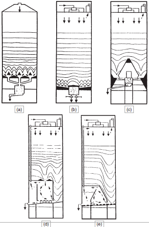
Figure 2.3.33. Continuous homogenization systems.
(a) CF silo of F. L. Smidth
(b) Multistream silo of Polysius
(c) Blending cone silo of Ibau
(d) Homogenizing chamber silo of C. L. Peters
(e) Mixing chamber silo of C. L. Peters

Figure 2.3.34. Gravity blending with a single outlet.
The dependence of the blending factor is primarily on the last two parameters. It is claimed that for effective blending with gravity systems, there must be a feed period of less than 4 hours and silo capacity between 8-12 hours. A feed period is defined as a sinusoidal curve crossing the control point three times. A blending efficiency level of 15:1 is apparently achievable with proper design of the gravity systems, and pressure as low as 0.27 bar can be utilized for silo extrac-tion. The conversion of existing systems to the gravity type has also been found feasible.
On the whole it is evident that for effective homogenization, various options are available and specific demands of a given situation can be comfortably met.
QUALITY CONTROL IN RAW MEAL PREPARATION
As already mentioned at the outset of this Chapter, the raw meal preparation process starting from the stage of quarrying to feeding into the kiln is a fairly complex one. The preparation of a correct and uniform kiln feed is an insurance for the quality of the finished product and entails the moni-toring of the quality of the incoming raw materials, composition of the preblending stockpile, vari-ation of the raw mill output in terms of chemical composition and particle size distribution, and finally the efficacy of the homogenization system and the consistency of its output forming the kiln feed. The monitoring and consequential control functions are carried out with the help of sampling arrangements, use of specialized analytical instruments, and application of appropriate computerized software.
Stockpile Buildup and Control
As already explained, the most established way to control the chemical composition of raw mate-rial coming from the quarry is through bed blending stockpiles provided with proper reclaiming systems. The mode of obtaining a homogenized stockpile through the use of a bulk material analyzer, software packages for controlling the additives, and stacker-reclaimer systems, respec-tively, has been elaborated on in the earlier sections. The bulk analyzer measures and provides the computer with the basic chemical composition of the bulk solid material on-line and in real time. The belt scale gives the computer the weight of the material flow in a given period of time, such as a minute. Further, the computer receives information from the stacker and the reclaimer regarding their location and speed. The computer, in turn, sends complete signals to schedule the quarry dumps, additives correction, and chemical data of the output. Finally the computer and the stock-pile PLC (Programmable Logic Controller) are fitted with necessary interfaces to exchange infor-mation with the central control room.
It is needless to emphasize that the effective control at the preblending stage contributes signifi-cantly to the chemical consistency of the final kiln feed.
Raw Meal Control
The basic steps of sampling, sample preparation, and sample flow for the analysis and quality control of raw meal are schematically shown in Figure 2.3.35. The analytical and evaluation requirements universally involve chemical analysis, the analysis of free lime in clinker, mineralogi-cal composition, and the particle size distribution of raw meal powder.
Online sampling in modern cement plants is done with automatic facilities. Representative samples are transported in capsules through a pneumatic dispatch system to a sample preparation station where the required quantity of raw meal is ground and either pressed into a tablet or fused into a bead (Scheubel, 1987).
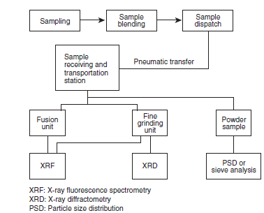
Figure 2.3.35. Schematic diagram, showing the preparation and flow of samples in the raw meal control process.
It may be mentioned that X-ray fluorescence (XRF) spectrometers are the preferred analytical tools in plant laboratories. Normally the simultaneous spectrometer is used for its simplicity, speed, and reliability. Today, however, it has often been necessary to determine trace elements and heavy metals for monitoring environmental protection measures. For this latter purpose it is necessary to use a sequential spectrometer. For such combined duties, a new series of instruments have been designed and manufactured that enables sequential and simultaneous analysis with the same instrument (Price and Siegenthaler, 1987).
A further improvement in instrument design has led to the development of what is now known as the Total Cement Analyzer (Yellepeddi and Bonvin, 1999). This analyzer integrates the appropriate X-ray modules such as an XRF monochromator, an XRF goniometer, and an X-ray diffraction
(XRD) system. The use of X-ray tubes and generators more powerful than the conventional 3 kW systems, allows enhanced sensitivities particularly for the light and mid-range elements. The inte-grated XRD system also benefits from this increased X-ray power since the same excitation condi-tions are used for both XRF and XRD within a single analytical program.
In XRF analysis, one of the factors that may affect accuracy is the matrix effect. In order to mini-mize these effects in conventional or routine analysis, fine grinding is resorted to in the sample preparation, followed by the adoption of separate calibration programs for separate types of samples.
The other alternative route for sample preparation is the fusion bead technique, which allows vari-ous types of samples to be analyzed in one calibration program with a very wide range for major oxides, ranging from 0.1 to almost 100% (Yellepeddi and Bonvin, 1999). The fusion bead technique can also be adopted with either precalcined or uncalcined powders. While the former is more direct and accurate, the latter depends on software to calculate the losses. The typical range of concentrations for various oxides in cement-related materials and their errors of determination are shown in Table 2.3.10.
The standard error of estimate is a combined effect of sample preparation error, measurement error, and other associated inaccuracies.
The integrated XRD system is based on parallel beam optics and operates under vacuum in the same manner as the XRF system. It is claimed that the free lime measurements or the measure-ments of CaCO3 in this system are highly stable and reproducible (Yellepeddi and Bonvin, 1999).
It has been a common practice to control the fineness of raw meal by measuring the residues on specific sieves, such as 200 and 90 mm. On the other hand, for the fineness of cement grinding today, a LASER-granulometer is preferred to determine the particle size distribution (Rawle, 1999). With the availability of such a facility in a laboratory, extension of this technique to measure and control the particle size distribution of raw meal may not be too futuristic.
Table 2.3.10. Analytical Ranges and Estimation Errors for Different Oxides in Cement Related Materials Achieved in the Modern XRF Facilities
Laboratory Automation
It has generally been the experience that the automation of laboratory systems and the quality control function enhances the efficiency of the entire plant system. A case study has been reported by Shafer (1999), who has brought out the intricacies of a system design and the basic considera-tions essential in such an exercise. In the given situation, the system design was based on the automation of the laboratory with the ability to introduce samples manually (Figure 2.3.36). The decision to employ pressed powder samples for chemical analysis was based on the need for analyzing sulfur and alkalies, and the synergy of using the same pellet for XRD analysis. Thus an automated mill, automated press, and an XRF instrument were necessary. Fineness analysis was needed for the cement process control and a laser diffraction particle size analyzer was employed. Free lime and calcination testing was required to support the existing high-level kiln control strat-egy. An XRD instrument was chosen. Finally, handling equipment was necessary for the integra-tion of the components. This included a series of small belt conveyors, x-y manipulation for the XRF instrument, and a robotic arm to act as a go-between for all the equipment.
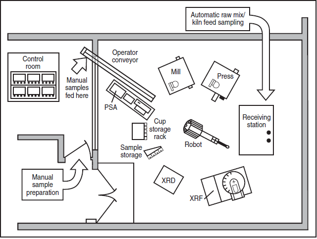
Figure 2.3.36. Layout of an automated laboratory.
Online Chemical Analysis
In addition to the previous considerations of material analysis in an off-line mode, the cement industry has always sought to develop a cost-effective method of online quality control. This requirement necessitated the development of large-capacity autosamplers such as the xy-magazine of ARL Company, which can handle both pressed pellets and fusion beads up to a capacity of approximately 100 samples. Its capacity and programming are more than adequate for a typical cement application. Sample identification and the selection of an analytical program can be carried out through a software connection from a remote PC using standard analytical softwares; alternately an external computer system can act as the master of the whole automation system (Yellepeddi and Bonvin, 1999).
It may be pertinent to mention here the development and application of Imacon analyzers in place of conventional analysis systems consisting of automatic sampling, sample preparation, and labo-ratory analysis (Raatikainen, 1999). These analyzers have two on-line models: one for bulk material analysis on conveyor belt installations and another for fine materials.
The Imacon analyzer is connected to the Process Management station, a PC computer that acts as the user interface to the analyzer. The Process Management station interfaces with the plant control hardware and has a database for the analytical facility. The station also has proprietary analysis calculation software and a reporting tool, as well as calibration and other facilitating soft-ware packages. The analyzer system can be connected with almost any commercial PLC.
It is claimed that the Imacon analyzers have been proven in many installations. Some typical performance values are shown in Table 2.3.11.
In Table 2.3.11, the static accuracy means the accuracy of calibration, where the Imacon analysis with 4-minute measurement time is compared with the analysis of the same samples by a state-of-the-art laboratory wavelength dispersive XRF spectrometer. The static precision test usually refers to the standard deviation of the 10-30 measurements of the same sample without removing the sample from the cell. The static reproducibility test is the same as the previous one, with the differ-ence that the sample is taken out of the cell and reintroduced for measurements. The dynamic accuracy is a comparison of the Imacon individual 4-minute analysis value of a sample with the analysis of the same sample by a wavelength-dispersive XRF instrument.
With such performance records, these kinds of analyzers seem to hold great promise for on-line operation.
Table 2.3.11. The Analytical Performance of an Imacon 100 Analyzer
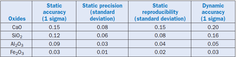
Computer Control Systems
The quality monitoring and control function in modern cement plants has been greatly facilitated by new technologies that use instrumentation, mathematical models, and computers for stable operations. As an illustration, one may make a reference to the new Expert Control and Suspension system supplied by the F.L. Smidth Co. to a cement plant (Glassburn and Wachal, 1998). This system is fully compatible with several brands of PLC. The system architecture included PLC on one side and a select set of computers communicating over a high-performance Ethernet Network on the other. The server used in this system enabled the integration of an
FLS/QCX/Laboratory system comprising both a Laboratory Information Management System (LIMS) and a Laboratory Automation System (LAS). The QCX/Laboratory/LIMS/Blend Expert module tracked raw materials in terms of quantities and composition, automatically adjusted feed-ers as necessary, and helped ensure adherence to the targets.
The analysis data are received automatically from the laboratory XRF. Upon completion of an analysis cycle, new feeder set points are calculated and automatically positioned. As reported by Glassburn and J. Wachal (1998), specific mill control operation capabilities included the following:
• Accounting on individual feeders
• Accounting on samplers
• Accounting for silo systems
• Accounting in accordance with product type and storage
• Range of analysis estimation techniques
• Linear quadratic optimization techniques
• Adaptive and/or predictive model based control
• Optimization in accordance with the material transport delays, mill dynamics, silo systems, and sample preparation/analysis characteristics
• Control bias compensation
The computer-based XRF-aided raw meal control systems embodying the above capabilities go along way in stabilizing plant operations, improving the kiln production, and enhancing, product quality.
REFERENCES
Bartholomew, Leslie, “Blending silos: advanced technology for new and existing installation,” International Cement Review, September 1995, pages 66-69.
Becker, J. F., “Roller mills: the largest and the smallest,” Cement Industry, 1995, pages 57-62.
Berthold, H., “Homogenizing effect of longitudinal and circular blending beds with bridge-type scraping reclaimers,” Proceedings of VDZ Congress ’77 on Process Technology of Cement Manufacture, Bauverlag GmbH, Wiesbaden and Berlin, 1979, pages 118-121
.
Biege, Neal W., and Bartholomew, Leslie, “Low cost, low power, high efficiency raw meal blending and silo withdrawal,” International Cement Review, April 1998, pages 86-90.
Birch, Erik, and Keefe, Brian P., “Experience with the OK roller mill,” Asian Cement and Construction Materials Magazine, September 1998, pages 40-44.
Brugan, J. Mark, “Upgrading raw mills,” International Cement Review, August 1991, pages 48-51.
Brundick, H., “Drying and grinding of extremely moist cement raw materials in the Loesche mill,” ZKG International, No.2, 1998, pages 64-71
.Brundick, Horst, and Schäfer, Heinz-Ullrich, “Loesche mills for clinker grinding,” Asian Cement and Construction Materials Magazine, September 1998, pages 52-57.
Brunkick, Horst, and Schafer, Heinz U., “Grinding advances,” International Cement Review,
June 1999, pages 61-66.
Buzzi, S., “BHG mill – a new grinding system,” Proceedings of VDZ Congress ’93 on Process Technology for Cement Manufacture, Bauverlag GmbH, Wiesbaden and Berlin, 1995, pages 697-700.
Buzzi, S., “The horomill – a new mill for fine comminution,” ZKG International, No.3, 1997, pages 127-138.
Carter, R. A., “New jaw crushers are reliable, affordable and transportable,” Rock Products, July 1999, pages 35-41.
Chatterjee, A. K., “Modernization of cement plants for productivity and energy conservation,” in Cement and Concrete Science & Technology (Ed. By S.N. Ghosh), ABI Books Pvt. Ltd., New Delhi, 1991, pages 99-139.
Conroy, G. H., and Wüster, H., “Industrial experience with high pressure comminution of cement clinker,” World Cement, No.7, 1986, pages 297-307
Drake, Bob, “The move to mobile in Minneapolis,” Rock Products, September 1999, pages 23-25.
Ellerbrock H. G., “High-pressure grinding rolls,” Proceedings of VDZ Congress ’93 on Process Technology for Cement Manufacture, Bauverlag GmbH, Wiesbaden and Berlin, 1995, pages 648-659.
Fischer, Gerhard, “Chevcon wins the day,” Asian Cement Magazine, August/September 1999, pages 28-30.
F. L. Smidth, “Crushing equipment from FLS,” Asian Cement and Construction Materials Magazine, June/July 1999, pages 17-19.
Flavel, M. D., and Rimmer, R. W., “Particle breakage studies in an impact crushing environment,” Paper presented at the SME-AIME Meeting, Chicago, Illinois, USA, February 1981.
Fouchardiere, Rene de la, “Horomill: one year’s operating experience,” World Cement,
September 1999, pages 98-105.
Glassburn, G. and Wachal, J., “Fuzzy logic and blending optimization at Lone Star,” World Cement, May 1998, pages 68-74.
Hasler, R., and Vollmin, K., “Present position of bed blending technology in the cement industry,” ZKG International, 12,1975, pages 25-31.
Heckert, Jerry, “Cone crusher automation,” Pit & Quarry, January 1999, pages 36-41.
Jung, O., “Developments and operational experience with vertical roller mills in the cement indus-try,” ZKG International, No.8,1999, pages 452-458.
Jung, O., “Thermal stressing in vertical roller mills when grinding very moist materials,” ZKG International, No.8,1998, pages 438-443.
Leclercq, L., “Duocast tyres – a new and proven technology for vertical roller mills,” ZKG International, No.3,1997, pages 148-153.
LV Technology Co. Ltd., and Hamada Blower, LV technology: small change, large gain, Asian Cement and Construction Materials Magazine, November/December 1999, pages 29-31.
Magotteaux, “The MAG’impact crusher from Magotteaux,” Asian Cement and Construction Materials, June/July 1999, page 27.
Mälzig, G., and Their, B., “Size reduction and homogenizing,” Proceedings of VDZ Congress ’85 on Process Technology of Cement Manufacture, Bauverlag GmbH, Wiesbaden and Berlin, 1987,pages 178-194
.
McCarter, John, “Crushing it right,” International Cement Review, February 1996, pages 51-57.
McCormack, David, “Which crusher?” International Cement Review, February 1996, pages 58-59.
Onuma, E., and Ito, M., “Separators in grinding circuits,” Proceedings of VDZ Congress ’93 on Process Technology for Cement Manufacture, Bauverlag GmbH, Wiesbaden and Berlin, 1995, pages 660-672.
PCR, Handbook of crushing, Pennsylvania Crusher Corporation, Broomall, Pennsylvania, 19008-0100, USA, 1998.
Price, B. J., and Siegenthaler, C., “A new generation of x-ray spectrometers for cement process control,” Proceedings of VDZ Congress ’85 on Process Technology for Cement Manufacture, Bauverlag GmbH, Wiesbaden and Berlin, 1987, pages 562-565.
Raatikainen, Jukka, “The new quality control tool,” International Cement Review, June 1999, pages 79-83.
Rawle, Alan, “Repeatable particle size analysis,” World Cement, June 1999, pages 56-61.
Scheubel, B., “Automated Monitoring system and Quality Control strategy in Cement Manufacturing,” Proceedings of 9th International Conference on Cement Microscopy, 1987,pages 123-146.
Schneider, U., “From ordering to operation of the first quadropol roller mill at the Bosenberg Cement Works,” ZKG International, No.8,1999, pages 460-466.
Schultz, A., and Lube, B., “Improving roller press grinding systems,” World Cement, June 1997, pages 28-34.
Shafer, Bruce, “Laboratory automation: a case study,” World Cement, June 1999, pages 46-49.
Sucre, Luis, “Raw material control,” World Cement, October 1998, pages 60-63.
Tschudin, M., “On-line control of the blending bed composition using PGNAA in Ramos Arizpe (Mexico),” Proceedings of VDZ Congress ’93 on Process Technology for Cement Manufacture, Bauverlag GmbH, Wiesbaden and Berlin, 1995, pages 259-266.
Wehr, Robert T., “Roller mill successes of the 1990s,” International Cement Review, April 1999, pages 57-59.
Woodward, Richard C., “Transforming preblending strategy,” World Cement, April 1997, pages 49-54.
Yellepeddi, R., and Bonvin, D., “Integrated Cement Analysis,” World Cement, June 1999, pages 73-78.