Contents
Every Thing you need to know about Raw Mix Design Considerations
[wpecpp name=”package” price=”75″ align=”center”]
by F. M. Miller*
The principal goal of raw material design and preparation is a kiln feed that permits effective, energy-conserving production of a quality portland cement clinker. Such clinker must have very restricted compositional targets. Since clinker must contain substantial portions of the elements calcium, silicon, aluminum, and iron, the raw materials (together with ash from the fuel) must provide these elements in particular. Typical percentages of these elements in clinker, expressed as oxides, are: CaO = 65 ± 3%, SiO2 = 21 ± 2%, Al2O3 = 5 ± 1.5%, and Fe2O3 = 3 ± 1%.
In targeting a mix composition with the raw materials available, the goal is somewhat akin to hitting a small bull’s-eye on a large target. Figure 2.2.1 shows the three-component phase diagram for the CaO–SiO2–Al2O3 system. The area indicated as portland cement is the only area that will yield acceptable cement properties. Wide deviations from this area will produce a product with
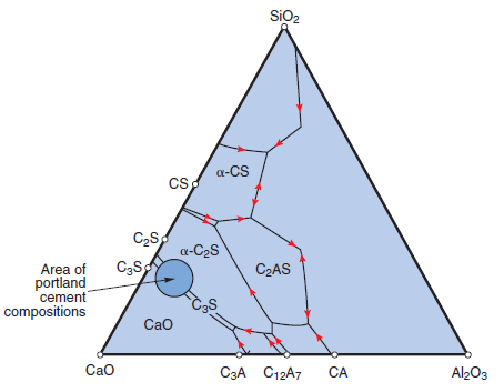
Figure 2.2.1. Three-component phase diagram for CaO–Al2O3–SiO2 system.
Innovations in Portland Cement Manufacturing
poor or no hydraulic properties, and even narrow deviations will result in a product with inferior performance.
RAW MIX FORMULATION
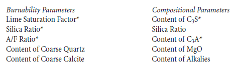
There are two equally important goals in designing the raw mix at a cement plant. On the one hand, the mix must be burnable – that is, it must be possible to achieve an acceptable free lime content in the clinker with a reasonable burning zone temperature, without suffering significant reductions in the production level of the kiln or inordinately short brick life. On the other hand, market considerations dictate that the composition of the cement be carefully controlled; that is, the contents of C3S, C3A, alkalies, and MgO must be held within fairly narrow, prearranged limits. The parameters of both types to be controlled are as follows:
Except for the coarse grains, and the alkalies and MgO, these goals can be simultaneously accom-plished by controlling the C3S or the lime saturation factor, the silica ratio, and the C3A or the A/F ratio. Both the LSF and the C3S reflect the ratio of lime to the acidic oxides (silica, alumina, and iron oxides) that combine with the lime, and the C3A and A/F ratio both mirror the relationship between alumina and iron in the mix. Therefore, controlling the LSF will of necessity also control the C3S level, everything else equal, and the same statement holds for the C3A and A/F ratio. We must, therefore, be aware of these relationships in order to properly prepare a suitable, burnable kiln feed.
The first goal in preparing raw materials is a thorough understanding of the raw materials that are available to the plant. Most cement plants are constructed at or near their source of calcium oxide, since lime represents about two-third of the clinker by mass. The composition of the limestone, which is generally the most important source of calcium, will dictate all requirements for ancillary raw materials to be chosen. At one extreme, the limestone may be nearly pure calcium carbonate. Under these circumstances, the amounts of other materials will be maximized. At the other extreme, the limestone may correspond to “cement rock,” such as is found in the Lehigh Valley of Pennsylvania or elsewhere. In such a case, the limestone may represent all, or nearly all, the raw mix. An intermediate limestone will probably represent about 80% of the mix by weight, as may a typical siliceous limestone. The compositions of four such limestones are shown in Table 2.2.1.
Raw Mix Design Considerations
Table 2.2.1. Typical Limestone Compositions, Mass %
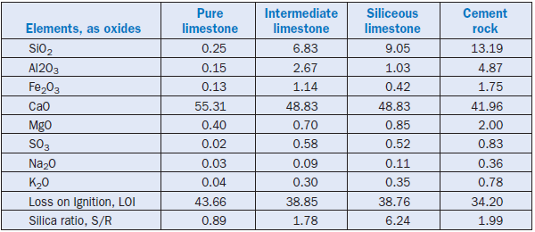
In examining these limestone compositions, there are several compositional factors of importance in addition to the CaO content. It will be noted that the typical required cement composition mentioned above calls for a silica content of about 21%, an alumina content of about 5%, and an iron oxide content of about 3%. The ratio of the silica content to the sum of the contents of alumina and iron, known as the silica ratio or silica modulus, is about 2.62. As we will see, for reasons of burnability as well as for quality, the ratio should probably not deviate greatly from this value. Therefore, the final raw mix should have a silica ratio near 2.62. The four limestones illus-trated in Table 2.2.1 have silica ratios of 0.89, 1.78, 6.24, and 1.99, respectively. Therefore, any candidate second raw material chosen to be used together with the limestones in Table 2.2.1 would need to have high silica content in three of the cases, and a low silica content in the case of siliceous limestone, assuming only one limestone source were to be used. Of course, if the same cement plant had available both an intermediate limestone (with composition similar to that in the second column of Table 2.2.1) and a siliceous limestone, the two could be used in combination to achieve a silica ratio of any value between 1.8 and 6.2. Under these circumstances, the choice of the low-lime component with respect to silica ratio would not be so critical.
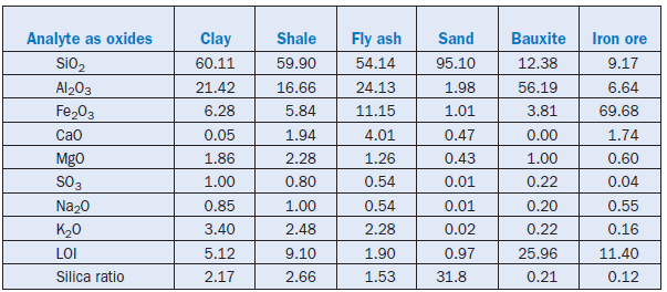
For a low lime component, some or all of the materials shown in Table 2.2.2 might be available. Shale and clay are often found as overburden or interbed inclusions in the limestone quarry –alternatively, they might be purchased materials. Fly ash (or the associated material bottom ash) may be available from power generating stations in the vicinity. All of these materials are consid-ered “argillaceous” materials, because they supply both silica and alumina, and often also iron, to the mix. Also shown in Table 2.2.2 are sand, iron ore, and bauxite. These materials supply essen-tially only one element (silica, iron, or alumina, respectively). As such, they will be considered additives, or corrective materials.
The silica ratio of the clay in Table 2.2.2 is low; as such, if it were used in conjunction with any of the first three limestones, an additional, strongly siliceous component would be required. For example, the silica sand could be used. The silica ratio of the shale in Table 2.2.2 is close to that of our target of 2.62. It would therefore be suitable for use with any of the limestones shown, provided that an additional component was available as a corrective material.
Table 2.2.2. Analysis of Typical Low-lime Materials, Mass %
Additives and Corrective Materials
In most cases, it is not possible to match all the goals of raw mix design with two components. This problem arises because it is usually necessary, for quality and burnability considerations, to control all of the following:
• The C3S or lime saturation factor
• The silica ratio, and
• The C3A content, or alternatively, the A/F ratio
It is a cardinal rule that the number of targets that can simultaneously be met in any mix design is equal to the number of raw components minus one. If there are three raw components, we can meet two targets, while if four components are to be used, three targets can be met. A further restriction is that at least one of the components must be above the target for the parameter in question, and at least one must be below the target. In other words, if we have a siliceous limestone together with high silica clay, we will need a bauxite, or an iron ore, or both, to achieve the desired composition. If the goal is a Type II mix, the need for iron may be greater, while if it is a high-C3A Type I, bauxite or other alumina source may be required. The composition of this additive mate-rial, while essential to meet the goal of mix composition, deviates greatly from the mix design target. Small deviations in its feed rate can have major effect on the raw mix composition parame-ters. Usually, therefore, the feeder for such materials must be sized for the feed rate range desired, and must be exceptionally accurate, to avoid large deviations from set point.
Compatibility Among Raw Material Components
The requirement noted above – that at least one raw material must have a value for any parameter higher than the target, and at least one material must have a value below the target value – is one of the main factors determining compatibility. Another, of course, has to do with the market require-ments for the cement. Factors other than the burnability and compound composition may dictate the proper design. The cement needs to pass volume stability requirements; this may limit the MgO content allowable, or it may have to pass an alkali limit. According to the optional provisions of ASTM C 150, for example, alkali content, calculated as Na2O equivalent, cannot exceed 0.6% by mass. In rare cases, the content of minor components may be of importance. The kiln feed chlo-ride level, for example, usually must be less than 0.015% for a preheater kiln without bypass. Phosphorus in excess of about 0.5% by mass may cause retarded setting. Fluoride at low levels
(perhaps about 0.25% by mass) acts as a mineralizer, but at higher levels can lead to excessive set retardation in the cement. Certain trace elements, such as lead, zinc, and boron, can have quality implications, while others, such as cadmium, thallium, and mercury, may have environmental implications, as they tend to be highly volatile at burning zone temperatures. Careful study of the composition of each raw material, and of the synergies or lack of synergies between them is neces-sary, to ensure that compatibility is achieved.
MIX DESIGN
Mix Design Calculations
As mentioned earlier, the target mix composition with the available raw material is the small area shown as portland cement in the three component phase diagram of CaO–SiO2–Al2O3 as already depicted in Figure 2.2.1. Cement produced with the composition indicated by only this area will have the desired hydraulic and engineering properties. Deviation from this composition will result in a product with inferior qualities.
Raw mix is controlled either on line or off line. In the on line mode, the raw mill product is analyzed frequently, and appropriate changes are made to the proportioning of the mix as needed to achieve the desired targets. The control can be considerably improved if feedback is available on the composition of the materials going to the mill. Cross belt analyzers are very effective in accom-plishing this goal. Computer programs are available to help achieve these mix corrections in a timely fashion, but the blending installation must be efficient for the correction to take place in a timely enough fashion. Most mix design calculations are based on a matrix model. It is strongly recommended that anyone responsible for mix control be familiar with the matrix calculation based on pairs of materials, illustrated in Appendix B. Once this process is thoroughly understood, it is probably sufficient to use a pre-packaged computer program for mix design, or to use the
“trial and error” or “hunt and peck” system with a spreadsheet format. In this latter method, the analyses of the raw materials available are listed on a spreadsheet, as shown in Appendix C. It may be helpful to convert the composition of the materials to an ignited basis, as they will be on this basis in the clinker. Once this is done, trial percentages of each of the components are multiplied by the content of each constituent in that component, and the incremental values are summed to achieve the total content of that element in the clinker. The fuel ash is a component of the clinker, and must always be added in, in the percentage that it would represent based on the actual fuel consumption of the kiln system. Appendix C illustrates an example.
Either the matrix calculation or the spreadsheet method may reveal that a given composition cannot be achieved with a given set of raw materials. The decision to abandon a given raw mate-rial, or to adjust the targets to accommodate it, must then be made on the basis of quality, economics, or operational considerations.
Industrial Wastes as Supplements
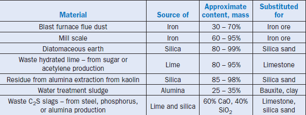
In recent years, there has been an increasing tendency to use industrial wastes as supplemental raw materials. One example of this trend is the use of fly ash, particularly that high in carbon content, as a source of silica and alumina. Also useful as an alumina source are waste fines from spent petroleum cracking catalyst. Such a material tends to be very high in alumina content, and can supply some additional non-quartz silica as well. Other substitutions that have been made benefi-cially are shown in Table 2.2.3.
The concerns in using alternate materials include chemical and physical aspects. Chemically, industrial wastes may contain trace metals or organic contamination that may limit their potential for environmental reasons. They may be very difficult to handle; for example, catalyst fines and even fly ash may require the use of pneumatic handling systems. Water treatment sludges or ponded fly ashes may be too wet for consideration by operators of dry process kiln systems, or alternatively, they may require that drying steps be instituted. In spite of these potential drawbacks, it is anticipated that cement kilns will continue to use these economical industrial wastes as raw materials. Innovative methods of introducing them will be found. For example, organic contami-nants may be dealt with by introducing the component directly to the calciner, or in a mid-kiln device for long kilns. Some slags are introduced unground as a separate feed stream to the kiln. Investigations using microscopy and other techniques have shown that the clinker uniformity is not severely compromised by such measures.
Table 2.2.3. Industrial Wastes as Substitute Raw Materials
Crushability and Grindability of Materials
One parameter of importance for natural and byproduct raw materials alike is the ease of comminution. With electrical energy constituting an ever-larger share of the total energy costs in operating a plant, reducing the crushing and raw milling energy requirements becomes increasingly important. Natural limestones generally are moderately easy to grind; on the Mohs scale of hard-ness, calcite has a value of 3. On the other end of the scale, quartz has a Mohs hardness of 7. In opti-mizing the mix particle size distribution, it is important to remember that good burnability of the kiln feed is dependent on grinding quartz to – 45 µm, while calcite needs only to be finer than 125 µm. The required finenesses of slag and feldspar are intermediate. Grinding a mix of limestone and quartz sand together will usually result in overgrinding of the limestone and undergrinding of the quartz. Replacing quartz sand with materials such as Tripoli or diatomaceous earth can save energy in grinding, and may permit burning at a lower temperature to achieve a given clinker free lime.
Industrial byproducts often have a very different grindability from that of the material they are replacing; among the evaluations that should be done to decide whether a natural raw material should be replaced by an industrial byproduct is determination of their relative grindabilities.
• As an example, it was initially thought that pot liner (from electrolytic aluminum production) might be a useful byproduct source of alumina and residual fuel (it has about 50% carbon content). However, aside from the classification of the material as hazardous, it usually has high fluoride and sodium contents, and most importantly from a processing perspective, it is very hard to grind.
• Foundry sand, as another instance, may sometimes be harder to grind than virgin silica sand –or at times it may be easier to grind.
• Under favorable circumstances, fly ash may be fed directly to the raw mill separator, since so much of it is already fine enough for introduction to the kiln, whereas bottom ash with simi-lar composition may have to be fed through the mill.
• Catalyst fines require no raw grinding at all, and may be fed directly to the blending silo, unless that device is not adequately efficient in blending disparate compositions (or if the catalyst is “clumped” and requires de-agglomeration).
• Slags will in general be very hard to grind, despite their suitable compositions. This problem has been addressed by introducing coarse slag (Young, 1996) to the kiln, which seems to work quite well in favorable circumstances.
In summary, then, since materials have such variable grindabilities, it is important to know the hardness of the individual mineralogical components, and to adapt the raw grinding circuit to optimize overall grinding to avoid over-grinding soft components.
Particle Size Distribution of Ground Materials and Their Process Effects
These considerations lead naturally into a discussion of the particle size distribution of the raw mix and its effect on the process. It is my firm view that the issue really is the presence of coarse grains in the mix. F.L. Smidth and others have derived equations for laboratory burnability of kiln feed that can be applied to commercial installations by appropriate modifications. The equations projecting free lime contents on the basis of the key parameters take the following form
(Christensen, 1979; Fundal, 1980; Johansen and Christensen, 1982; Miller, 1981):
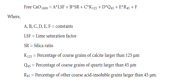
The above equation can also take the form:
![]()
![]()
Where, G is another constant.
The majority of the kiln feed is limestone, which does not have to be finer than 125 µm. If an argillaceous limestone (cement rock) is used, it may be possible to obtain good burnability at particle sizes considerably coarser than this (since the effective calcite grain size is smaller than the particle size). The quartz in the mix, however, can hamper burnability if it is coarser than 45 µm (325 mesh). Feldspars and slags can hinder the reactions at particle sizes > 63 µm.
Therefore, it may be advantageous to characterize the overall fineness on the 125 µm sieve, and then acidify the mix and examine the coarse fractions (principally 45 µm) for their content of the grains of concern. Grinding the feed too fine can result in excessive dust carryout from the kiln, as well as wasting electrical energy from grinding.
REFERENCES
Christensen, N. H., “Burnability of Cement Raw Mixes at 1400°C” Part I, Cement and Concrete Research, Vol. 9, pages 219-228, 1979.
Christensen, N. H., “Burnability of Cement Raw Mixes at 1400°C” Part II, Cement and Concrete Research, Vol. 9, pages 285-294, 1979.
F. L. Smidth, www.flsmidth.com, http://www.flsmidth.com, 2004.
Fundal, E., “The Microscopy of Cement Raw Mix and Clinker,” FLS Review #25, F. L. Smidth Laboratories, Copenhagen Denmark, 1980.
Johansen, V., and Christensen, N. H., “Laboratory Burnability and Practical Kiln Operation,” 84th Annual Meeting, Cement Division, American Ceramic Society, 1982.
Lea, F. M., and Parker, T. W., Paper No. 16, Building Research Technology, HMSO, London, England, 1935.
Miller, F. M., “Microscopy as an Aid in Evaluation of Mix Burnability and Clinker Formation,” Ciments, Betons, Platres, Chaux, No. 731, 1981.
Ono, Y., “Microscopical Estimation of Burning Condition and Quality of Clinker,” 7th International Congress on the Chemistry of Cement, Paris, Vol. 2, Theme 1, pages 206-211, 1980.
Young, Rom D., Method and Apparatus for Using Blast Furnace Slag in Cement Production, U.S. Patent No. 5,494,515, assigned to Texas Industries, Inc., 1996.
APPENDIX A
Definitions of Burnability and Compositional Parameters
- Lime Saturation Factor (LSF) – A measurement of the degree of conversion of silica, alumina, and iron oxide to their most highly basic calcium compounds.
![]()
![]()
- Silica Ratio (SR) – A measurement of the ratio of silica to that of the sum of aluminum and iron oxides. Inversely proportional to the liquid phase at burning zone temperatures.

- A/F Ratio – A measurement of the ratio of alumina to iron oxide. This ratio can influence the rate of development of clinker liquid in the burning zone; in the presence of 2% or more MgO, a ratio of 1.63 gives the maximum liquid phase at the minimum temperature.
![]()
![]()
- Content ofCS – This is usually calculated using the Bogue equations. While not strictly accu-rate, it is a good indication of the sort of level of C3S, or alite, that will be experienced in clinker. It is frequently used as a burnability parameter as well as a compositional parameter.
![]()
![]()
If the composition parameters are given on an ignited basis, the calculation gives the antici-pated clinker alite content, assuming that ash has no effect on the composition. The term with sulfate in the equation is typically included only for cement, where gypsum has been added to the product.
• Content ofCA – This is also calculated using the Bogue equations. If analyses are expressed on an ignited basis, it predicts the C3A level in the clinker, assuming the fuel ash has no effect on composition.
• Liquid Phase – This is calculated according to the time-honored formula of Lea and Parker
(1935), as follows: % Liquid = 2.95 Al2O3 + 2.25 Fe2O3.This simple formula is used because although MgO and alkalies contribute to the liquid phase, a portion of the alumina and iron are incorporated in the silicate phases. The “plusses” and “minuses” almost balance each other out.
APPENDIX B
Steps to Matrix Calculation of Mix Design
• You may set one fewer target than the number of mix components available. If you have three raw materials, use two targets. If you have four raw materials, use three targets. As an example, set the calculated clinker C3S at 60%, the clinker C3A at 7.5%, and the clinker liquid phase
at 23%.
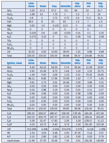
• Set up the chemical analyses of the individual raw components, and calculate the ignited basis compositions of the materials. See Table A2.2.1 for an example.
• Choose pairs of raw materials to achieve the first desired target. In this example, we choose limestone and shale, limestone and clay, and limestone and iron ore. Limestone is the only material with more than 60% C3S on an ignited basis, whereas the other materials are all below 60%. The resulting blends may be called blends A, B, and C.
• Calculate the difference between the target C3S and the C3S content of the individual materi-als. Sum these differences, and determine the relative proportions of the two materials that will give the target. See Table A2.2.2 for an example of steps (3) and (4).
• Calculate the C3A and clinker liquid phase in blends A, B, and C (Table A2.2.2).
• Blends A and B are above the C3A target of 7.5%, and Blend C is below it. We therefore combine A with C and B with C to achieve the C3A target, as shown in Table A2.2.3. These two combinations are termed “Blend D” and “Blend E.” The liquid phase contents in Blend D and Blend E are calculated. Fortunately, Blend D is above the clinker liquid target, and Blend E is below it.
• Blends D and E are proportioned to achieve the desired liquid phase target, as shown in Table A2.2.4. The proportions of D and E are then converted to the corresponding proportions of the binary mixtures A, B, and C, and these in turn converted back into the proportions of the original raw materials on an ignited basis, also shown in Table A2.2.4.
• The ignited basis raw mix is converted into the “as received” basis by dividing by (1 – loss on ignition, expressed as decimal). This raw mix proportioning is then checked, by calculating the raw mix composition resulting, converting to an ignited basis, and determining whether
Table A2.2.1. Raw and Ignited Basis Compositions, Raw Materials, Mass %
the desired targets have been reached. This calculation is illustrated in Table A2.2.5.
• If the fuel ash has an impact on the clinker composition, it must be accounted for. The easiest way may be to adjust the raw mix composition targets first. For example, if the coal ash will represent 1% of the clinker, and it has a C3S of -594.0, a C3A of 49.8, and a potential liquid phase of 96.7%, the targets of the previous exercise should be adjusted to the following:
■ C3S = 65.94/0.99 = 66.61
■ C3A = 7.002/0.99 = 7.07
■ Liquid Phase = 22.033/0.99 = 22.25
When these targets are reached, the coal ash will correct them to the original desired targets.
APPENDIX C
Mix Formulation by Trial and Error
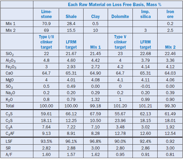
1. Table A2.2.6 restates the composition of the raw materials for this exercise.
2. The desired loss free raw mix composition is determined by back calculation from the clinker.
3. Various percentages of the individual raw materials are tried, multiplying the percentage by the amount of silica, alumina, etc., and summing the incremental percentages. The final result is compared with the desired target, and the percentages of individual raw materials are adjusted to approach the target LFRM more closely. Table A2.2.7 shows the percentages of the individual raw materials that achieved a close match with the targets, for a Type I-II raw mix (mix 1).
4. Table A2.2.7 also shows the percentages for a Type V raw mix (mix 2). Here, the imported silica and iron ore are used in place of some of the shale, to achieve the lower C3A levels required.
Table A2.2.2. Selection of Pairs of Raw Materials and C3S Calculation
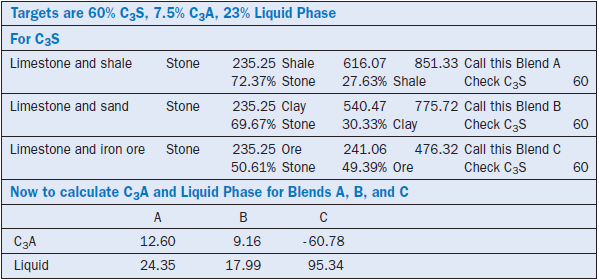
Table A2.2.3. Selection of Pairs of Binary Pairs, and Calculation of C3A
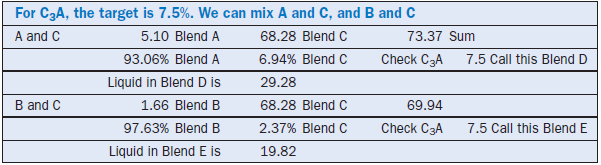
Table A2.2.4. Calculation of Final Blend and Back Calculation of Ignited Basis Proportions
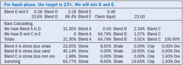
Table A2.2.5. Determining Raw Basis Proportioning and Checking Results
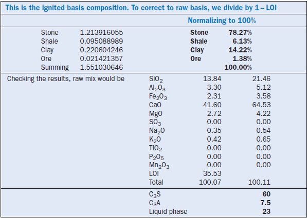
Table A2.2.6. Raw Material Compositions, Mass %
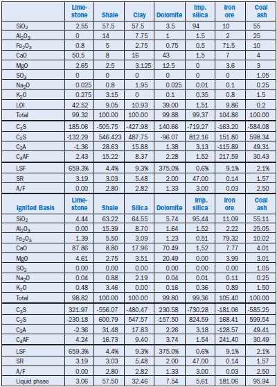
Table A2.2.7. Trial Mixes