Contents
Everything you need to know about Cement Fuel Selection and Use
Clement Greco*†, Guido Picciotti*, Renato Barros Greco*, and Guilherme Martins Ferreira*
[wpecpp name=”package” price=”75″ align=”center”]
The appropriate selection and use of a fuel has always been and still is a matter of great concern for the cement industry. This essential material is always vital when used in the kiln for clinkering and secondarily in dryers of raw materials or additives, in hot gas generators, etc.
The current fierce competition in the cement market and the high impact of the item “fuel cost” in the final price of the product is making companies look for the most economic mix to fire in their kilns. This search should be carried out with due attention to the quality of the clinker and should be environmentally friendly. Currently, this search, because of new combustion processes, should also include a systemic view of the overall conditions of actual fuel availability and of the short-and medium-term new trends of availability of new kinds of fuel.
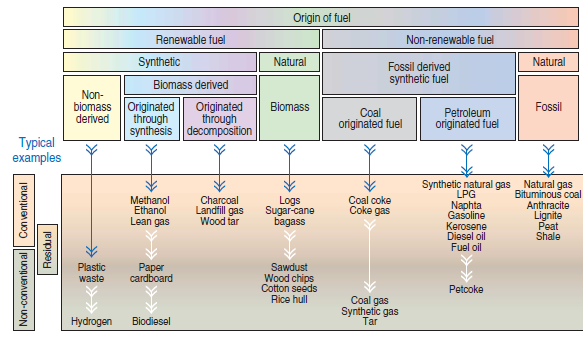
Figure 2.5.1. Fuel classification chart according to its origin with typical examples.
FUELS OVERVIEW
There is a large variety of fuels that can be “categorized” according to different criteria. Taking into consideration the deployment at cement plants, a widely-used classification is the tree-shaped chart that reflects both the origin of the fuel and the way it is traditionally used (see Figure 2.5.1); the chart includes typical examples of fuels currently used by the cement industry. All fuels are substances that in the presence of an “oxidant” – usually, but not exclusively, atmospheric air – and provided there is an “initial energetic impulse,” give rise to a chemical reaction of oxidation that is exothermic, self-sustainable, and very rapid. Because it happens very fast, the rate of heat transfer mechanisms (conduction, convection, and radiation) are not adequate to promote dissipation into the environment of the thermal energy at the same rate it is released by the conversion of the chemical energy. Consequently, there is heating of reaction products and the generation of a “hot thermal reservoir” used in several industrial processes as an energy source.
Fuels are substances with energy-rich bonds – such as carbon/carbon, hydrogen/hydrogen, or carbon/hydrogen – that, if released, convert the chemical energy into thermal energy. In this cate-gory we find essentially compounds of carbon, hydrogen, nitrogen, and sulfur, in which oxygen is often present as a binding element that makes no contribution to energy release. Carbon and hydrogen are the elements that add the greatest energetic contribution to the fuel; nitrogen and sulfur not only bring a less significant energetic contribution, but they also create products with a high environmental contamination potential.
It is important to highlight that fuels are part of the primary matrix of energy that supplies the needs of human beings, and that they meet these needs in variable proportions according to the natural availability and current status of technical and scientific knowledge. Figure 2.5.2, prepared according to information gathered at the World Coal Institute (WCI) website, shows the matrix participation in the last 150 years of the most traditional fuels such as coal, oil and its byproducts, natural gas, and biomass – and forecasts the distribution for the next 150 years. In this chart, the area identified as “traditional renewables” shows the energy used in the firing of materials found in nature that are renewable or can be recovered in a short period and used without concern for a controlled recovery, such as wooden logs.
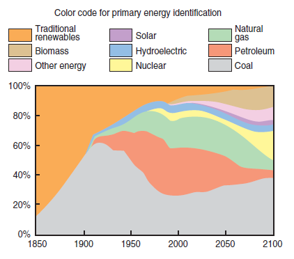
Figure 2.5.2. Primary energy distribution world-wide from 1850 up to 2100 (forecast).
PHYSICAL AND CHEMICAL CHARACTERISTICS OF FUELS
The physical and chemical characteristics of fuels play a major role in the combustion process, in the clinker production process, and in the emission of atmospheric pollutants. These characteris-tics vary from fuel to fuel and can only be shown qualitatively – as in this chapter – when broken down under those titles that introduce each fuel. It is possible – and interesting from a teaching point of view – to introduce as early as possible all these characteristics and present the phenome-nological concept of each of them, their implications in the deployment of fuels in the cement industry, and the symbols that will introduce them, as well as the units used to represent them in the tables shown in this chapter.
Physical Characteristics
The physical characteristic of a fuel that most influences the firing process is the phase in which it becomes available for combustion. Solid, liquid, and gas fuels burn according to different mecha-nisms and kinetics. When used in cement kilns, solid fuels are normally pulverized before use and pneumatically transported to the kiln into which they are injected with the conveying air; liquid fuels are always nebulized when they are fired; and gas fuels are simply injected into the kiln.
Additional Physical Characteristics
Other physical characteristics, i.e., other physical properties of the fuel that are important for establishing its conditions of use and fire are:
Specific heat. This property translates the “amount of heat needed to increase by one degree the temperature of one unit of mass or volume of a substance,” and it is a function of the temperature. It is significant, for instance, in determining the energetic consumption during heating processes in the preliminary preparation needed for an efficient firing of fuels. For specific heat, commonly used symbol is cp, measurement usual unit is kJ/kg per °K and kJ/Nm3 per °K.
Thermal conductivity. This property measures the “capacity of a substance to transfer heat through molecular mechanisms,” and is a function of the temperature. It is important, for instance, in determining the heat exchange coefficient and the size of any heat exchanger used in heating processes in the preliminary preparation necessary for an efficient firing of fuels. For ther-mal conductivity, the normal symbol is k and the usual unit of measurement is W/m per °k.
Density or specific mass. This property translates “the mass of one unit of volume of a substance.” It usually depends on the temperature and, in the case of gases, it depends also on the pressure. Its importance depends on its influence over other significant properties, such as viscos-ity. For viscosity, the commonly used symbol is r and the usual measurement unit is kg/m3.
Relative density or specific gravity. This is another way of showing the density of a substance, i.e., translating it into its quotient based on a reference substance density – for liquids, water at 15°C, and for gas, air under standard temperature and pressure conditions. For specific gravity, most common symbol used is, SG; it is a dimensionless quantity.
In some countries, the relative density of liquids is presented in 0API, on a scale of values related with the SG through the formula,
0API = (141.5/SG) – 131.5
Flammability limit. This property “defines the range of concentrations of a gas fuel mixed with air able to self-sustain a flame.” The two thresholds of this range are called the “lower flammability limit” and the “higher flammability limit,” and they correspond to the least and greatest concentra-tion of fuel that meets those conditions in the definition of this property, respectively. The flam-mability limits, which usually depend on the temperature of the air/fuel mix, are important for characterizing the conditions of ignition and extinction of the flame of a gaseous fuel, for instance. Commonly use symbols are LFL and HFL, respectively, for lower and higher inflammability limits, where the usual measurement unit is % volume.
Heating value. This property measures the “amount of thermal energy released after the complete firing of a mass unit or of a volume unit of fuel,” considering both the reactants and the products at the same reference state. The mass base is usually applied to solid and liquid fuels, and the volume base is applied to gas. Two “heating values” are defined for any fuel according to the phase in which the water of the combustion products is found, that is:
Higher heating value, that considers the water of the combustion products in a liquid phase. Commonly used symbol is HHV, whereas the usual measurement unit is kJ/kg, or kJ/N m3.
Lower heating value, that considers the water of the combustion products in a gaseous phase. Commonly used symbol is LHV, whereas the usual measurement unit is kJ/kg, or kJ/N m3.
The heating value is, simply, a property that determines the energetic availability of the fired mass or volume unit and is, therefore, a parameter of paramount importance in the analysis of use of a fuel.
Pour point. This significant property for liquid fuels means the “lowest temperature above which the fuel flows in a liquid form under controlled conditions.” The pour point defines, for instance, the minimum requirements for heating certain fuels, such as ultraviscous oils. Commonly used symbol is PP, whereas the usual measurement unit is °K.
Flash point. This significant property for liquid fuels means, “the lower temperature under which vapors are created in enough quantity to form over the free surface a mixture with air that starts a fire whenever exposed to an ignition source.” The flash point signalizes the volatility of a fuel and supplies important parameters to define its ignition conditions and storage requirements. Commonly used symbol is FP, whereas the usual measurement unit is K.
Viscosity. A very intuitive and not very technical form of characterizing this property is by defin-ing it as “a measure of the resistance of a fluid to the flow;” strictly scientifically, viscosity is defined as “a macroscopic measurement of the internal resistance that a fluid presents to the movement of adjacent layers.” Under normal conditions of fuel-use by cement plants, it depends essentially on the temperature and can be translated into two interrelated properties:
• Dynamic or absolute viscosity. Most commonly use symbols is m, whereas the usual measure-ment unit is kg/m.s and, in technical papers and tables, centipoises
![]()
![]()
• Kinematics viscosity, which is measured by the quotient between the dynamic viscosity and the density. Most commonly use symbols is n, whereas the usual measurement unit is m2/s and, in technical papers and tables, centistokes
![]()
![]()
Viscosity is a characteristic of fuels that impacts both movement and flow/firing mechanisms. If power consumed by a pump or a fan, for instance, is greater, the greater the viscosity of the fluid provided all other parameters are not altered. The impact of viscosity on flow and firing mecha-nisms can also be seen in the transition from a laminar condition to a condition of turbulence, or on the turbulent transportation of energy and mass, and so on.
Adiabatic Flame Temperature
A physical characteristic that is always assessed whenever selecting a fuel for a specific purpose is the “adiabatic temperature of the flame.” It is defined as a temperature of the products of combus-tion in a full, adiabatic firing process – i.e., without any heat exchange with the environment – and under constant pressure, applying an oxidant in a quantity at least equal to the stoichiometric requirement. The last part of the definition – “applying an oxidant in a quantity at least equal to the stoichiometric”- shows clearly that the adiabatic temperature of the flame is not a thermody-namic property of the fuel; the same kind of fuel fired with the same oxidant, such as atmospheric air, will show a lower flame adiabatic temperature, when excess air is available. A fuel fired under the stoichiometric volume of air will show an adiabatic temperature that is higher, the more enriched with oxygen the air is.
Chemical Characteristics
The chemical characteristics of a fuel, i.e., its immediate and elementary analysis, have an impact on the heating value, on the flame adiabatic temperature, in the firing mechanisms, and on the emissions and residue resulting from combustion.
The behavior of fuels is dependent on whether the fuel is simple i.e., essentially a sole chemical species, or involves multi-components – that is, a mix of several chemical species in matching contents. Multi-component fuels show different firing behavior from those formed by a sole chemical species. This“firing difference” is much more sensitive in liquid or gaseous multi-component fuels that, because of the different vapor pressures of the substances involved, can be consumed in different points and intervals within the flame, thus determining a complex kinetics that must be carefully considered and controlled so that emissions hazardous to the environment are not generated.
PARAMETERS FOR FUEL SELECTION
Whenever a fuel is selected, either to be deployed as the sole energetic input to a cement kiln or to be used in a mix, it is not enough to analyze and weigh its “energetic parameters” such as heating value, its possibilities for thermal use such as flame temperature and firing conditions, or its opera-tional features such as ease of handling, impact on product, etc. During the selection of a fuel for a cement kiln it is also very important in our current social and economic scenario to analyze and weigh certain parameters as described in the following sections.
“Triangular Balance”
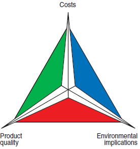
Figure 2.5.3. The “triangular balance.”
The final choice of a fuel is always a result of a match among three factors that can be shown, as presented in Figure 2.5.3, by the vertex of an equi-lateral triangle – namely, cost, product quality, and impact on the environment. The fuel that best meets the specific needs of a cement plant is that which is ideally placed “closest” to the center of gravity of this triangle. This “triangular balance” determines the effective conditions of use of the fuel if operational cost includes all the necessary expenses involved in the firing process and all the expenses influenced by this firing process. It should include, without being restricted to, items such as:
• Fuel purchase.
• Amortization of the investments made in the firing systems, storage system, fuel conditioning and transportation, post-treatment system for combustion gases, etc.
• Operation expenses of fuel systems and the treatment of combustion gases.
• Maintenance expenses.
Strategic Factors
It is important to keep in mind that if cement cannot be produced without raw material, neither can it be made without fuel. Therefore, it is essential that the selection of the fuel or fuels in a mix that will be used in a cement kiln be guided by strategic factors that should include, but not be restricted to:
• Short, medium, and long term availability.
• Transportation facilities.
• A possible cartel involving suppliers.
• Dependence on imports, with a special focus on supplies coming from regions subject to political instability.
• Convenience and feasibility of having a broad range of supply options.
• Environmental impact – a marketing element that is becoming more recognized throughout the world.
Sulfur Content
Sulfur is an important parameter because of the oxides that it creates during firing, known as a group by the acronym SOx,with all the environmental implications and impact on the quality of clinker.
Environmental implications result mainly from SO2 formed at high temperatures and from SO3 formed at low temperatures. The “rates” of production of these compounds depend also on condi-tioning factors associated with the firing reaction, such as the local excess O2 content. Because of the high temperatures in the rotary kilns, SO2 is most frequently present in the stack emissions. SO2 is a colorless gas with a sharp odor that can be extremely corrosive in the presence of water. It is an aggressive pollutant that damages both the respiratory system of human beings and the vege-tation, since it creates acid rain by ready transformation into sulfuric acid (H2SO4) in the presence of water. Nevertheless, SO2 emissions from cement kilns are relatively low if compared to the emis-sions from other equipment firing the same fuel – boilers and furnaces, for instance – because a significant part of the sulfur is incorporated by the clinker. Kilns with calciners and/or preheaters tend to emit less SO2 than long-dry kilns and wet kilns. Quality implications of the fuel sulfur content result from the reaction that takes place involving sulfur dioxide, oxygen, and the alkalis found in the raw material.
Nitrogen Content
Every time a fuel is fired in the presence of atmospheric air which contains approximately 79%nitrogen, nitrogen oxides known as NOx are formed. Nitrogen oxides resulting from the reactions between nitrogen and oxygen present in the atmospheric air – so-called “thermal NOx”– are inherent in combustion itself, and their concentration is increased with the increase of tempera-ture during the process. It is, therefore, very important to control, through the aerodynamics of the flame, those mechanisms in the cement kiln that give origin to this “thermal NOx.” If, nevertheless, the fuel contains “chemically combined nitrogen,” an additional amount of it will appear in the combustion products called “fuel NOx.” This NOx results from the direct oxidation of nitrogen organic compounds present in the fuel due to many intermediate reactions that can be summa-rized in the following global reaction:
RiN + O2 → NO, NO2,CO2,H2O, and traces of other species
After the NO is formed, it reacts quickly at low temperatures with the oxygen and is oxidized into
NO2,a very active oxidizing agent. Nitrogen dioxide is, actually, the main “environmental evil” because:
• NOin contact with water creates two highly corrosive acids: nitrous acid (HNO2) and nitric acid (HNO3). When this contact occurs through the passage of rainwater in a highly NO2 concentrated atmosphere, the result is “acid rain” – a very important driver of vegetation and building destruction.
• NOcontributes to atmospheric pollution by forming “smog” because the mix of NO2 and free non-fired hydrocarbon radicals creates, under the action of solar radiation, “smog” result-ing from a photochemical reaction.
Precursors of Dioxins and PAHs
Dioxins and PAHs (polycyclic aromatic hydrocarbons) are pollutants that can damage the environ-ment seriously because of their carcinogenic and mutagenic potential. Dioxins also have a terato-genic potential. The mechanisms that form dioxins and PAHs are still under study. Nevertheless, it is, certain that the presence of “precursors” in the fuel plays an important role in the emission of these pollutants, a good reason to survey their presence and know their content in the fuel, i.e.:
• “Precursors” that form PAHs: acetylene hydrocarbons.
• “Precursors” that form dioxins: polyvinyl chloride (PVC), chlorobenzenes, chlorotoluenes, chlorophenols, and sodium chloride.
Only by evaluating, quantifying, and comparing, case by case, all the technical, economic, strategic, and environmental parameters involved in the use of a fuel it is possible to achieve a solution that provides the best balance of cost, quality, and environmental security.
FUEL OIL
Fuel oil is widely used in the cement industry because in its liquid phase it is very easy to fire. It originates from fossils because it is an oil byproduct essentially formed by parafinic, olefinic, naph-thalenic, and aromatic hydrocarbons.
The American Society for Testing and Materials (ASTM) defines fuel oil as “any oil product that is liquid or may turn into liquid, and that is fired to produce heat in a kiln or a furnace or even fired to generate power to an engine, except for those products that present a flash point below 100°F (37.7°C).” This is a very broad definition that includes oil itself; products distilled from oil, includ-ing tail products up to lighter fractions; and mixtures of oil products with different characteristics.
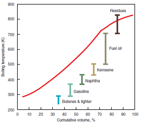
Figure 2.5.4. Crude oil distillation curve.
The commercial definition is more limited and focused on industrial applications of fuel oil. According to this definition, fuel oil includes the heavier fractions – distilled between 500°K and 700°K – and residues from the oil distillation process with densities and viscosities ranging from 800 kg/m3 to 1,100 kg/m3 and 2 cSt to 750 cSt (under a temperature of 310°K), respectively, as shown in Figure 2.5.4, prepared using the information and data found in the John Zink Combustion Handbook (Baukal). Within this range of properties, fuel oil was classified initially into six categories and later reduced to only four, based on viscosity, density, and the firing require-ments of heating and nebulization (transformation of the liquid into a cloud of droplets through its injection at a high speed into a gaseous atmosphere):
#1 Fuel Oil
#1 Fuel oil is the lightest and least viscous of all fuel oils. It is a light colored product obtained from fractional distillation of oil. It needs no preheating and is easily nebulized for firing purposes.
#2 Fuel Oil
#2 Fuel oil, also a product from the distillation of oil, is separated under higher temperatures than those deployed for #1 fuel oil. It is a light-yellow liquid that does not need preheating and can be nebulized for firing purposes by mechanic means, i.e., under pressure injection through an appro-priate nozzle.
#4 Fuel Oil
#4 Fuel oil is typically a mix of distilled fractions and liquid residues from oil distillation. It has, therefore, some characteristics that are intermediate between those found in the other three kinds of fuel oil. It is considered an oil difficult to fire and requires some special care during nebuliza-tion. Nevertheless, it can be fired without preheating.
#6 Fuel Oil
#6 Fuel oil, also known as bunker C oil, is a residual liquid fuel from oil distillation. It is the heavi-est and most viscous of ASTM fuel oils. Efficient firing can be accomplished only after it has been conveniently nebulized through either high pressure or the use of an auxiliary fluid, such as steam or compressed air. Moreover, because it is very viscous, it needs to be heated, handled, and fired. For pumping purposes, the oil heating temperature for #6 fuel is around 335°K; for firing purposes, around 375°K.
Table 2.5.1 shows the parameters established by ASTM for the four kinds of fuel oil currently in the market. Within these parameters, there is a broad variation of characteristics, shown in
Table 2.5.1. Requirements for Fuel Oils (per ASTM D 396)
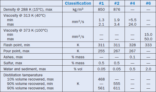
Table 2.5.2 – also prepared based on information and data collected from the book of Baukal, Jr. –where the typical characteristics of fuel oils are listed. It is important to highlight that Table 2.5.2 shows typical averages and is offered for purposes of illustration only, since the properties of fuel oils depend significantly on the origin of the oil and on the refining process.
Table 2.5.2. Typical Analysis of Different Fuel Oils
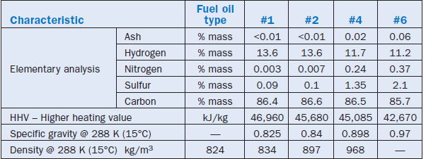
Usually, the heavier the fuel oil, the lower is the price of a unit of energy released during its firing. Even considering the secondary costs incurred because of the need to prepare it for handling and firing – i.e., pre-heating – the price of the unit of energy released in firing fuel oil #6 is the lowest of all fuel oils. That is the reason it is used in industrial applications, particularly in cement plants, and why some specific characteristics of this oil have been detailed in this chapter.
There is no specification for a maximum sulfur content in #6 fuel oil, and it is possible to
state that:
• The content of sulfur depends, essentially, on the origin of the oil and, less impor-tantly, on the refining process.
• The mass content of sulfur in #6 fuel oil may reach 5%, but usually ranges between 2% and 4% as shown in Figure 2.5.5, a histogram showing sulfur content in oils used worldwide.
• The greater the content of sulfur in the oil; the greater the emissions of SOx into the environment, provided all other conditions remain equal.
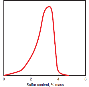
Figure 2.5.5. Histogram of sulfur content in #6 fuel oil world-wide deliveries.
•The presence of sulfur reduces the heating value of the fuel oil; this reduction can be consid-ered equal to 290 kJ/kg for every 1% of sulfur in the fuel.
#6 Fuel oil contains the highest amount of ash compared to the other four types of fuel oil because it is the heaviest fraction in the oil distillation, which concentrates the residues. It is, therefore, possible to affirm that:
• In #6 fuel oil the mass content of ash may reach 0.08% and is usually between 0.03% and 0.07%, as shown in Figure 2.5.6, a histogram showing the content of ash in oils used worldwide.
• The content of ash in the fuel oil essen-tially depends on three factors 1) inor-ganic material found in raw matter, i.e., the origin of oil, 2) the refining process structure, and 3) possible contamination during operation procedures, transporta-tion, and/or storage.
• Ash influences and reduces the heating value of #6 fuel oil. This reduction can be considered equal to 20 kJ/kg for every 0.05% of ash by weight of fuel.
• Fuel oil ash contains vanadium, silica, aluminum, sodium, and iron, as the main components.
• Vanadium contents higher than the usual level of 100 mg/kg, as shown in Figure 2.5.7, are potentially hazardous if combined with a high content of sodium, because of their characteristic as corro-sion inducers at high temperature.
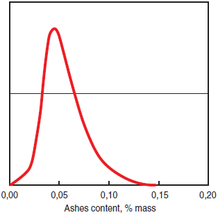
Figure 2.5.6.Hisstogram of ashes content in #6 fuel oil world-wide deliveries.
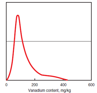
Figure 2.5.7.Hisstogram of vanadium content in #6 fuel oil world-wide deliveries.
The ease of ignition of #6 fuel oil depends both on its viscosity and its density. Usually the “quality of ignition” is linked to an empir-ical index called CCAI – Calculated Carbon Aromaticity Index – that can be estimated through the following formula:
![]()
![]()
In this equation, the density is measured at 15°C with units of kg/m3, and the kinematic viscosity is measured at 50°C with units of mm2/sec. Fuel oils with CCAI between 800 and 870 have no prob-lems of ignition, whereas those with CCAI > 870 have an ignition issue.
In many countries, fuel oil is sold on volumetric terms, i.e., its price is established according to a volume unit (liter, cubic meter, gallon, etc.) whereas its heating value is always specified on a mass basis as in kJ/kg. In this situation, it is very important in the evaluation of a fuel to consider both heating value and density, so that the price paid for the thermal energy released during the firing process is well known.
As a final comment, it is important to highlight that for cement plants worldwide, the growing demand for lighter fractions – diesel oil, for instance – has brought some changes to raw refinery process that, consequently, gave origin to a “waste” that has properties – density, pour point, and viscosity –making it much more difficult to handle, store, and fire than the conventional ASTM-listed fuel oils. These are the ultraviscous oils that, because of economic factors, have assumed a significantly more important share of the energy matrix commonly used by cement plants. The characteristics of ultraviscous oils vary largely according to their origin. It can be stated, though, that they have high kinematic viscosity – around 1000 cSt at 400 K – and they require higher temperatures during pumping and firing – around 390 K and 450 K up to 470 K, respectively.
NATURAL GAS
Among the gaseous fuels, i.e., those that exist naturally in a gaseous form under normal tempera-ture and pressure, natural gas is currently the most widely used.
Natural gas is a fossil fuel formed by hydrocarbons created by the transformation throughout millions of years and under the action of pressure and temperature of plant and animal wastes that remained buried under many layers of land and rock. It has been present in human life since the beginning of time without being identified and used as a fuel – a “leak” of natural gas through the rock, accidentally ignited by some natural factor, created a “fire” more than 3000 years ago that became the legendary Oracle of Delphi in Greece!
Since the properties of natural gas and its application potential were not promptly identified, it took a while to have its use as a fuel recognized. By the late 19th century, for instance, the use of natural gas as a fuel was restricted to consumers near the wells from which it was extracted. The major gas pipelines only became a reality in the second half of the 20th century; they were respon-sible for spreading the use of natural gas as a fuel in households, commercial facilities, and indus-trial sites. Natural gas is not only widely used by thermoelectric power plants, but also as a fuel in industries that share the need for major energy inputs – cement industry, pulp and paper, glass, ceramics, etc. In 1990, natural gas accounted for 24% of the total consumption of energy in the U.S.; it is forecasted to grow to 29% by 2020. This growth in the share of natural gas in the energy matrix is a worldwide trend, as shown in Figure 2.5.8 which forecasts the next decades according to information collected at the website of the United Nations Conference on Trade and Development (UNCTAD).
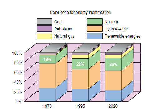
Figure 2.5.8. Natural gas share of the energy matrix world-wide.
Natural gas is a mixture of hydrocarbons with a low boiling point, with a variable composition, and with a broad predominance of methane (CH4) in volumetric contents that vary between 70%and 99.6%. Ethane (C2H6) is the second most frequent component in natural gas, whereas propane (C3H8), butane (C4H10), carbon dioxide (CO2), nitrogen (N2), hydrogen (H2), oxygen
(O2), and even heavier hydrocarbons appear depending upon the origin, in smaller amounts. Actually, the natural gas that is “delivered” through gas pipelines to be distributed to consumers is different from “raw natural gas,” i.e., from the products extracted from reserves. These contain impurities such as water, sand, and hydrogen sulfide (H2S). Before being delivered the impurities in the raw natural gas are eliminated, and often other components are removed as well. It is impor-tant to note that the removal of water is critical, and should be carried out to avoid problems in the gas pipeline such as increased corrosion and the possibility of line blockage, because of solid hydrated compounds formed.
The removal of water is important and should be carried out to avoid problems in the gas pipeline, such as:
• Corrosion increase.
• The possibility of line blockage because of solid hydrated compounds that are formed.
• The appearance of ice and the consequent damage to valves and instruments is also a major problem for gas pipelines crossing low-temperatures regions during winter.
The removal of hydrogen sulfide is carried out in order to reduce its content to volumes lower than 0.02 g/m3 to minimize:
• Environmental problems due to the firing of natural gas with high contents of hydrogen sulfide.
• The risks of corrosion in the gas pipelines and in the distribution network.
Many times, natural-gas inert components are removed – i.e., components that add nothing to the energetic balance when fired – to avoid wasting energy during the transportation of products that have no commercial value as fuels and can be sold for other purposes; that is why CO2 is often removed from natural gas before delivery.
Also, components with higher commercial value that can be sold separately are removed from raw natural gas, as in the case of propane extracted to be sold for the production of petroleum lique-fied gas.
The previous remarks show that the composition of natural gas distributed for industrial consumption depends both on its origin and on the specific conditions established in the supply contract. Table 2.5.3 shows some typical compositions of natural gas from different origins, while Table 2.5.4 shows typical conditions established in a contract for supplying natural gas. Both tables were prepared from information in the Zink Combustion Handbook (Baukal).
Table 2.5.3. Typical Composition of Commercial Natural Gases from Different Origins
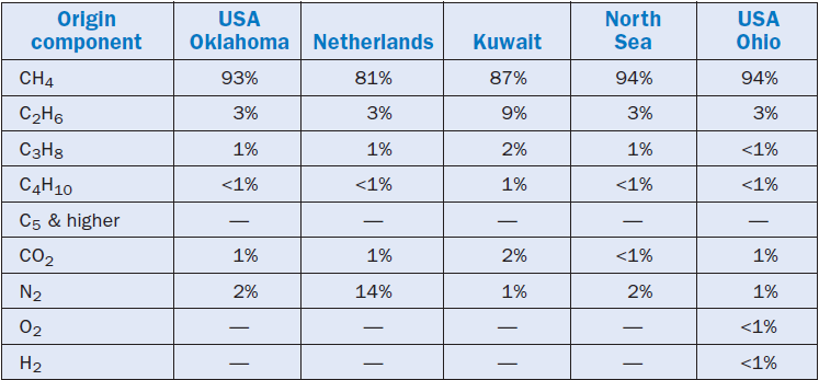
Table 2.5.4. General Data on a Canadian Natural Gas Ready for Utilization
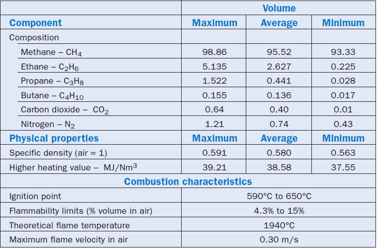
It is impossible to compile and show accurately the typical properties of the fuel in a table because of the great variety of natural gas supply contracts. Nevertheless, it is important to mention these properties, at least as a reference. Therefore, Table 2.5.4 was included in this chapter for reference; the table also shows the main physical and chemical characteristics of natural gas supplied by a certain Canadian distributor.
The natural gas that is distributed for consumption is exclusively methane, a colorless, odorless, and non-toxic gas. Because of this lack of odor, natural gas is odorized before it is delivered through the pipelines by mixing with butyl mercaptan that creates a characteristic and unpleasant smell. Very small amounts, 4 ppm maximum, of mercaptan added to natural gas is enough to odorize it. Mercaptan is a sulfur compound whose generic formula is R-SH, where R is an aliphatic or an aromatic organic radical. By odorizing the gas, it is possible to easily identify any natural gas leakages, as well as the accumulation of this fuel in a confined environment – a condition under which its continued breathing may cause dizziness and numbness.
Critical Highlights of Natural Gas
There are several critical advantages in utilizing natural gas as fuel; some are described as follows:
Higher heating value. It is important to know that natural gas has a higher heating value per mass unit compared to all other fossil fuels
Cleanest fuel.
Natural gas is the “cleanest” of all fossil fuels. Since it is essentially formed of methane, the products from its combustion are water and carbon dioxide, the same products exhaled from breathing of living beings. The contents of the “great evils for the environment” are actually reduced to sheer traces in natural gas combustion products. Moreover, the firing of natural gas does not generate either ash or particulate emissions. Table 2.5.5 shows an interesting quantita-tive comparison of pollutants emitted during the firing of the three classic fossils: bunker C oil, coal, and natural gas. This table was prepared based on fuels with a typical average composition and equally efficient firing of all three fuels. It should also be pointed out that the cement kiln, as a general rule, emits more NOx and less SOx than the corresponding figures shown in Table 2.5.5.
Table 2.5.5. Typical Emission Levels for “Classical” Fossil Fuels
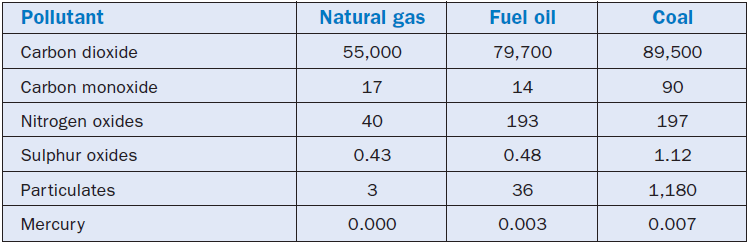
Lesser “greenhouse effect.” The growing use of natural gas can be an important factor in reducing the “greenhouse effect” because, as can be understood through the analysis of Table 2.5.5, the firing of natural gas emits 31% less CO2 than fuel oil, and 38% less than coal, with the same energetic effect!
Reduced “smog” effect. Another potential environmental advantage to the use of natural gas as fuel is the possible reduction of “smog” and ozone in the lower layers of the atmosphere. Fuel NOx is practically not generated, and volatile organic compounds are also not produced. However, thermal NOx may be more of a problem with gas fuel than with solid fuels, since with gas the flame must generally be hotter to achieve the same radiant heat transfer as with solid fuels.
These considerations justify the belief of many environmentalists that natural gas is the inevitable transition between aggressive fossil fuels actually used and clean and renewable fuels that will be progressively used in the future, as populations and governments recognize the magnitude of envi-ronmental problems.
Natural gas is not a renewable fuel, so its increased use should be followed by an accurate evalua-tion of its availability. It is important to note that:
• Reserves of natural gas have been discovered at a much more intense pace than the discovery of crude oil reserves. In 1970 the known reserves of natural gas represented 50% of the reserves of crude oil in terms of energetic equivalence; currently, this percentage is around 95%!
• The development of new methodologies for the discovery of reserves using 3-D seismology, and of new extraction technologies which make it possible to explore deeper reserves with smaller diameter drills at a competitive cost, enabled the identification of new potential deposits of natural gas.
• In the year 2000, according to UNCTAD evaluation, the known reserves of natural gas whose exploitation was feasible according to techniques available at the time were 150 trillion cubic meters, a volume that can meet world demands for the next 70 years, assuming historical rates of consumption growth are maintained.
• The technicians believe that many large-volume reserves of natural gas are yet to be found.
• The actual reserves of natural gas are distributed broadly around the globe, as shown in Figure 2.5.9.

Figure 2.5.9. Natural gas resources world-wide.
Marketing Natural Gas
As for marketing natural gas, the following factors needs to be considered:
• The tariffing of natural gas is usually made based on the energy supplied, i.e., a price such as in USD/MJ is established for a certain amount of energy supplied.
• The unit price of natural gas is usually differentiated for various classes of consumers: indus-tries, electric power stations, commercial use, and households. Within each class there are differentiated tariffs according to the volume of consumption (daily or monthly).
• In some countries the supply of natural gas follows a seasonal structure, i.e., during certain periods of the year it may be restricted to certain consumers. This is the case in certain coun-tries with cold climates where in winter the supply of natural gas is prioritized to household and commercial consumers that need it for heating purposes. The consumption for industrial consumers is then restricted.
• The price of natural gas for the end-user depends on three factors: the cost of gas at the well, conditioning and long distance transportation costs, and distribution costs. Despite the oscil-lations and specific conditions to which each of these cost items is subject, there is a “uniform world trend” in the evolution of the price of natural gas, as shown in Figure 2.5.10.

Figure 2.5.10. Natural gas price evolution and comparison in five important consumer areas.
The readers of this chapter, end-users of a fuel, will notice an example that shows how the world market of natural gas is organizing itself to guarantee supply and increase its participation in the energetic matrix of several countries. The LNG – Liquefied Natural Gas – technique was developed to enable natural gas transportation to those countries that do not have gas pipelines. When cooled down to –165°C, natural gas becomes liquid and is transported through long distances in specially designed ships or trucks with thermal insulation tanks. Although LNG involves considerable production costs, research and economic feasibility provided by more economic techniques of liquefaction and later evaporation of the fuel are turning the LNG into a very attractive alternative to natural gas transportation. In its liquid phase, natural gas occupies a volume 1/600th of the volume it would occupy as gas. Moreover, LNG makes feasible the exploitation of deposits that currently present technical, economic, or political restrictions for the construction of a gas pipeline for delivery. Although today LNG represents only a fraction of the volume of natural gas sold – in the U.S., for instance, this fraction is 1% – it is projected that this share will grow significantly in the next few decades.
COAL
Coal is a fossil fuel that has been in use since the beginning of time. There are ancient historical records, dating from the Roman Empire, about the coal market among peoples in different regions. In the 19th century, coal was the fuel that boosted the Industrial Revolution; in the 20th century, it was the engine for the expansion of electricity and was responsible during the first decades of that century for supplying more than half of the energetic demand of the planet. Currently, coal is still a responsible source-link of almost a fourth – 23% exactly – of the world’s energy demands. Figure 2.5.2 clearly shows the role of coal as an important component of the fuel primary energy matrix. It is important to highlight that in the figure a “drop in the contribution” can be seen more or less by the end of the first 25 years of the 20th century. This drop initially was a result of the increased share in the energy matrix of oil by-products, and later of natural gas, mainly because of lower costs of extracting these fuels compared to coal. For an equal energy potential, the cost of exploit-ing a coal mine is 20-fold higher than exploiting an oil or a natural gas reserve! This drop was also a result, though on a smaller scale, of the migration of small consumers to oil by-products and natural gas, because they were attracted by the easy handling and storage of these new kinds of energy. Despite all this, coal remained a major source of primary energy in the world up to the first years of the second half of the 20th century, when it was surpassed by oil by-products. Currently, though, coal is the primary source most used for electric power generation, and it is responsible for supplying approximately 35% of the world’s electricity consumption.
The importance and status of coal among fossil fuels is a result of 5 major factors, namely:
1. Abundance
2. Safety
3. Market stabilit
4. Attractive price
5. Duration of reserves
Coal is the most abundant fossil fuel and geographically the best distributed fuel. More than 50 countries in the world have significant and active coal mines. Coal is a stable fuel and a safe one, too, considering transportation, storage, and use. Coal availability for users is quite steady because of its abundance and the multiplicity of countries that produce it. These two conditions together guarantee an extremely competitive supplier market, i.e., a market with attractive prices that are not subject to seasonality, local political and economic instabilities, etc. Considering the unit of energy released during firing, coal price is globally very competitive compared to fuel oil and natu-ral gas, especially for major consumers such as large electric power generators and cement plants.
Recent estimates forecast that the known coal reserves are adequate to meet world demands for the next 200 years if current levels of consumption and growth rate remain the same – a “lifespan” greater than that forecasted for oil byproducts and natural gas, in terms of reserves already identified.
Stages of Coal Formation
Coal is a fossil fuel of organic origin that is essentially composed of carbon, hydrogen, and oxygen. Coal is, actually, a modified residue of prehistorical plants that passed through a process called carbonization, which occurred in three distinct and successive geological stages:
Microbial stage. The microbial stage resulted in the formation of the initial peat – a dark-colored, hydromorphous soil with a spongy texture – through the decomposition of the remainder of plants piled in swamps, marshes, and ponds under favorable environment conditions, i.e., a damp acidic environment lacking oxygen, which prevented the quick decomposition of organic material by bacteria.
Biochemical stage. The biochemical stage corresponded to the transformation of peat into coal. This transformation occurred because the process of formation of peat was interrupted after it had been covered by successive layers of sedimentary material accumulated through tectonic movements of the earth’s crust and by the “invasion” of seawater.
Geochemical stage. The geochemical stage corresponded to the full metamorphosis of the peat as a result of the compaction caused by the thickening of sedimentary deposits. The high pressures and high temperatures to which the organic matter was exposed for long periods brought on a final modification to its structure and an extraordinary compaction that in some cases reduced the initial thickness of the stratum by 95%!
The first carboniferous deposits originated about 400 million years ago, whereas the most recent started forming only 15 million years ago. The older the carboniferous deposit, the more complete the metamorphosis of the organic matter of a fossil fuel, and the greater the amount of energy released in firing the mass unit. This metamorphosis – the carbonization – depends on 7 factors that determine the final characteristics of each coal found in nature:
1. Temperature – the primordial cause
2. Time
3. Igneous intrusions
4. Environment of organic matter accumulation
5. Pressure
6. Structural deformation of the stratum of organic matter
7. Initial composition of the plants that originated the coal
Ranking of Coal
There are so many factors impacting on the “level of metamorphism” of coal that in nature it is possible to find coals of many different kinds. For commercial and technical standardization purposes, it was therefore necessary, to group these coals in “classes.” The classification most used and standardized by ASTM takes the “level of metamorphism” as a basis and distributes coals into four ranks in the ascending order of completion of transformation:
1. lignite
2. subbituminous
3. bituminous
4. anthracite
Figure 2.5.11, as re-created based on a model found on the WCI site, shows the ranking of the different coals.
“Low rank” coals. The so-called “low rank” coals – i.e., lignite and subbituminous coal – come from more recent carboniferous deposits and are friable with a muddy feature, and no gloss; their color varies from brown to opaque black, and they show a high content of moisture and low content of carbon.
“Hard” coals. The so-called “hard” coals – i.e., bituminous coal and anthracite – come from ancient carboniferous deposits. They are very consistent, mechanically resistant and hard; black, shiny; and have low content of moisture and high content of carbon.
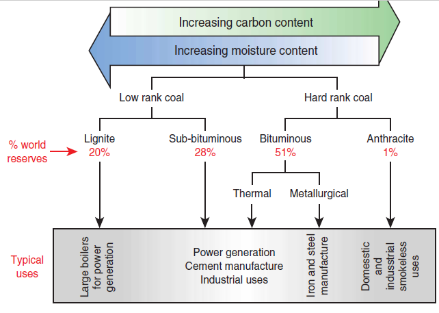
Figure 2.5.11. Coal ranking.
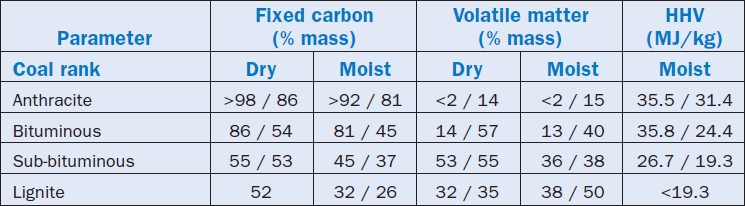
The ranking of a coal, although a measurement of its “level of metamorphism,” corresponds to typical average values of physical and chemical parameters important for their use and marketing, namely:
• Fixed carbon content
• Volatile matter content
• Moisture content
• Higher heating value
Table 2.5.6 shows the typical ranges of the values of the properties of coal in ranks; it is worth highlighting that all values in this table are understood as in “mmf basis,” i.e., in a mineral matter-free condition.
The different coals also show different physical features that can be described in terms of the four ranks, namely:
• Lignite is a soft, highly brittle, brownish-black solid known as “brown coal.”
• Bituminous coal is a dense, black solid, frequently with alternating bright and opaque stripes.
• Subbituminous coal is a solid with variable characteristics between lignite and bituminous coal.
• Anthracite is a very hard and resistant soil of black color and a semimetallic gloss.
Table 2.5.6. Classification of Coals by Rank
As shown in Figure 2.5.12, coal that is broadly used worldwide has typical uses according to its rank:
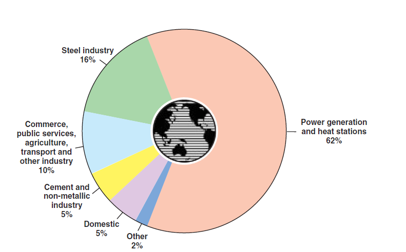
Figure 2.5.12. Coal utilization around the world.
Lignite Coal
Lignite shows characteristic features such as lower heating value and high moisture content, that do not justify huge energy expenditures to transport it to long distances; it is essentially consumed closer to the deposits where it is extracted, usually to produce electric power.
Bituminous Coal
Bituminous coal is very abundant in nature and is the most widely used of all coal types. It shows a broad range of variation of its characteristic physical and chemical parameters and, for that reason, it is often placed in subgroups:
• According to the content of volatile matter, bituminous coal can be classified as:
■ Low volatile bituminous coal with a content of volatile matter below 22% dmf (dry and mineral free mass basis).
■ Medium volatile bituminous coal with a content of volatile matter between 22% dmf and 31% dmf.
■ High volatile bituminous coal with a content of volatile matter above 31% dmf.
• According to its use, bituminous coal can be classified as:
■ Thermal coal, which is used as fuel for boilers, kilns, etc., and has to satisfy fewer restric-tions concerning other nonvolatile matter components, and
■ Metallurgical coal, whose features – low content of ashes and sulfur, for instance – make it appropriate for the production of metallurgical coke.
Subbituminous and Thermal Bituminous Coal
Subbituminous coal and thermal bituminous coal are used essentially as fuel to:
• Generate electricity.
• Generate steam for the creation of high temperature thermal reservoirs to be deployed in industrial processes.
• Generate steam for traction purposes.
• Public heating systems.
• To meet households needs – food cooking, heating of water for personal hygiene, heating of environments, etc.
Metallurgical Bituminous Coal
Metallurgical bituminous coal as the name shows, is used essentially in the production of coke which is:
• A primary input for producing iron and steel.
• Also used in other industries of metal production.
Anthracite
Anthracite is the least common and most expensive of the coals. It has some unique features – the capacity, for instance, for a smokeless fire – and it is used for specific purposes:
• The direct heating of wealthy households.
• A reducing agent for some industrial processes – the manufacture of glass and chemical prod-ucts, the treatment of ferrous metals, etc.
• Injection in steel mill kilns as pulverized fuel.
The ranking of coal gives us the opportunity to do a very comprehensive analysis of this fuel. It should be highlighted, though, that it is not the only classification that exists for coal: it is simply the most widely accepted. The United Nations (UN), for instance, developed an “international classification” for coal that uses a three digit numbering code – the first digit (from 0 to 9) trans-lates, simultaneously, the content of volatile matter and the heating value; the second (from 0 to 7) translates the agglomeration characteristics; and the third (from 0 to 5) translates the suitability of coal-to-coke conversion. The ranking system was developed by ASTM to initially classify and stan-dardize the coals produced by the mines in the United States and it is, therefore, highly appropriate for these coals. Nevertheless, it does not take into consideration some of the parameters that have a major impact on the quality of coal as well as the firing conditions, and the resulting environmen-tal impact – the content of ashes and sulfur, for instance.
Ash Contents
The content of ash in any type of coal plays no influence in its “ranking” because the specifications for fixed carbon content and volatile matter are made based on a mineral matter-free condition, which does not include ash. They are, though, always present in a greater or lesser amount in all coals and it should be highlighted that:
• Ash can be both minerals closely associated with coal with which they became incorporated during the carbonization process, and they can also be discrete particles of incombustible material combined with coal during mining and handling processes.
• Ash is usually formed by mineral clay, carbonates (calcite, dolomite, and siderite), sulfides (pyrites, galena, and sphalerite), and silicates (quartz).
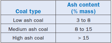
• Coal,internationally, is divided into three groups according to the content of ash, as shown in Table 2.5.7, in which contents are specified in dry basis.
•Medium ash type coal is best accepted by the international market because it adds to a favorable price an acceptable content of ashes; for this market, a typical value for the content of ashes that defines a coal of good quality is 10%.
•The content of ashes of a coal depends, essentially, on its origin; in Australia, for instance, bituminous coal and subbituminous coal have ash contents on a dry basis that vary from 8%–25%, whereas coal in the United Kingdom has an average ash content of 15%.
Table 2.5.7. Coal Classification by Ash Content
Ash effects. Ash has an important impact on the quality and on the technical and economic conditions for the use of coal.
A high content of ash produces a lower heating value for coal received “as is” and greater trans-portation costs per unit of thermal energy released in firing, because of the expense of transport-ing incombustible material. High ash coals also require additional care during firing because of the following reasons:
• When ash is released as small particles, it is carried along by combustion products, and since it is not combustible, it is not eliminated on post firing. This ash requires special treatment, so that it can be removed from the gas through bag filters, cyclones, electrostatic precipitators, etc.
• High content of ash may delay combustion, because a large amount of incombustible material compared to the combustible species may cause the former to encapsulate the latter, thus
“preventing” their firing.
• Ifthe temperatures resulting from the combustion are high enough, the ash may melt and form slag. The molten material may “group itself ” and form bigger size particles that are easily removed from the combustion products. Nevertheless, two adverse effects may occur, 1) They might “envelop” smaller particles of fuel that, in this condition, would pass through the firing zone untouched and would be launched as pollutants into the atmosphere, and 2) They might promote the wear and tear of internal parts in the combustion chamber.
When coal is fired inside equipment such as boilers or heating furnaces, a high content of ash implies high investment and operation costs for the removal and final rejection of ash after combustion – a problem of major magnitude when we bear in mind that the typical user of coal as fuel is, essentially, a major consumer.
When coal is fired in cement kilns, the ash is incorporated into the clinker and, therefore, it is important to adjust the composition of the raw material to the ashes so that this inclusion does not change the quality of the final product (cement).
When coal ashes are rich in SiO2,wear problems may arise in the pneumatic conveying lines.
The problems caused because of the occurrence of high contents of ash are so serious that many times a “previous conditioning” of coal is performed, right after being extracted from the mine and before being delivered to the end-user, so that ashes content is reduced. This reduction may, for instance, be accomplished through raw-material washing when a significant part of the non-fuel material is in the form of discrete particles aggregated to the organic matter.
Trace Elements In addition to the ash, other substances and compounds are usually found in coal – the “trace elements.” As the name itself suggests, the contents of these substances and compounds are usually sufficiently low to avoid diminishing the heating value of coal, or to significantly add any parasitic cost to transportation. It is necessary, though, to know them and to carefully weigh the interfer-ences and impacts they will have both in the firing process and on the emissions into the environ-ment. Vis-à-vis the most frequently found “trace elements” in coal are discussed as follows:
Sulfur. Its content varies broadly from 1% to 5%, according to its origin, and it is certain that:
• Although sulfur is responsible for adding some heating value to coal, there are serious envi-ronmental implications because during firing it is oxidized into SO2.This SO2,when intro-duced into the O2 rich atmosphere, is transformed into sulfuric acid (H2SO4) by action of humidity creating acid rain.
• When coal is fired in a cement kiln, it is necessary to consider carefully the effects that its sulfur content may have in the “sulfur cycle” and in the quality of the clinker.
Chlorides, sulfates, and nitrates. They usually bring corrosion problems to the parts inside the kiln system; chlorides are particularly harmful to clinker production.
Sodium. It incites ash precipitation and, consequently, a decrease in the energy efficiency of the firing process.
Phosphorus. It is responsible for formation of slag inside the furnace.
After the general characteristics of coal as a fuel have been introduced and discussed, it is timely to highlight the important technological developments during recent decades that made coal firing energetically more efficient and environmentally cleaner. Currently, the use of coal no longer bears the negative image associated with it during the first half of the 20th century – large clouds of black smoke coming out of a chimney! Associations of coal producers, governmental entities, and research laboratories accepted and are winning the challenge of changing coal into a fuel as compatible with the environment as any other fossil fuels. New mining, firing, combustion gas post-treatment technologies, and efforts to manage greenhouse effects are turning coal into a “vali-dated” clean fuel for the 21st century. This is especially true in terms of a combined analysis of the environment impacts associated with production, use, and an eventual reuse of final products, the so-called “Life Cycle Analysis (LCA).” It should also be highlighted that LCA is a modern approach to the environmental interference of combustion, and that it supplies much more significant and realistic results than the sheer “tip of the burner” analysis carried out a few years ago!
PETCOKE
Much has been said about the preferred fuel of cement plants being that which offers, in general terms, “the cheapest unit of energy” without hurting the final product quality, of course. This“axiom of cement plants” helped promote petcoke in this last decade from a waste fuel to a classical fuel – actually, one of the most widely used fuels in cement kilns worldwide because the cost per unit of released energy during firing is, usually, cheaper compared to coal and fuel oil.
Petcoke is a black, shiny solid presented as small granules or “needles.” It is an oil refinery byprod-uct that results from the thermal decomposition of heavy oils. In the composition of petcoke we find mainly carbon, although it can also show high levels of sulfur and heavy metals, such as nickel and vanadium.
Classification of Petcoke
Petcoke can be classified for marketing and for the specification of its characteristic properties according to two nonmutually exclusive criteria, namely:
Classification by production process. By this criterion, three types of petcoke are defined as follows:
1. Delayed petcoke is the petcoke resulting from a semicontinuous process of production called delayed coking developed originally to minimize the production of heavy liquid waste fuels through their thermal cracking. This kind of petcoke features:
• A significant content of residual hydrocarbons.
• Volatile material content between 10% and 15%.
2. Fluidcoke is the petcoke resulting from a continuous fluidized-bed coking oven specially developed for transforming coke so that it can be used as a fuel. This is actually the most appropriate process for processing raw materials that show a high content of sulfur.
3. Flexicoke is the petcoke resulting from a continuous fluidized-bed coking process through which most of the coke is turned into gas to produce a low-heating value gaseous fuel that is deployed at the refinery itself. Among the three types of petcoke, flexicoke has the lowset content of volatile materials – between 2.5% and 3.5%.
Classification by conditions of delivery. By this criterion, two types of petcoke are defined as follows:
1. Green coke is the petcoke in the form it leaves the coking process. Green coke is, therefore, petcoke “as-produced” and it shows the following features:
• Volatile material found in green coke consists essentially of hydrocarbons, which include PAHs – polycyclic aromatic hydrocarbons; these hydrocarbons provide green coke with its characteristic odor.
• Carbon essentially comprises the nonvolatile fraction.
• Ash/inorganic content is relatively low.
2. Calcined coke is the petcoke that is “treated” and obtained from green coke by heating it in a rotary kiln under a reducing atmosphere and temperatures above 1480°K (1200°C), following a process during which most of green coke hydrocarbons are removed. Calcined coke is, thus, almost free of volatile material.
The world petcoke production has grown steadily, leveraged by its attractive price. It grew around 50% between the late 80’s and late 90’s, reaching 50 Mt in 1999. The production growth exceeded 60% during the last two years to meet an increasing demand, and in 2001 it reached the 82 Mt mark. Figure 2.5.13 shows North America as the region that produces the most petcoke in the world; nearly 70% of the world production comes from this region, and the United State is respon-sible for 90% of this total. It should also be highlighted that almost 60% of the North American production of petcoke comes from the same region – the area on the coast of the Gulf of Mexico including Texas and Louisiana. North America’s status as a great producer should actually become even more apparent in the short and medium terms either because of the discovery and exploita-tion of oily sand deposits in Canada, or because of the expansion of the production capacity of the already existing American refineries.
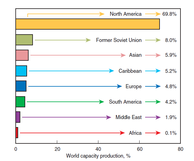
Figure 2.5.13. Petcoke regional production capacity.
A look at worldwide use of petcoke shows that in addition to the Unite States, Japan, Canada, Spain, Italy, Germany, France, and the United Kingdom are the major consumers. As shown in Figure 2.5.14:
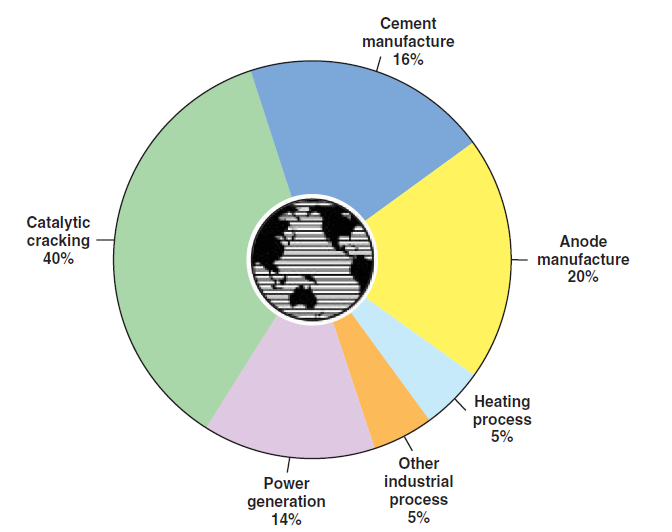
Figure 2.5.14. How petcoke is used around the world.
• Nearly 75% of the world petcoke production is used as energy source in:
■ For cement manufacturing
■ By the oil refineries
■ For generating electric power
■ In other direct or indirect heating processes in several industries
• Nearly 25% of the world petcoke production is not used as an energy source; it is used in the form of calcined petcoke, as raw material, mainly for the production of anodes used in the production of steel and aluminum. To a lesser degree it is also used in the automotive industry for manufacturing auto parts, tires, graphite parts, etc.
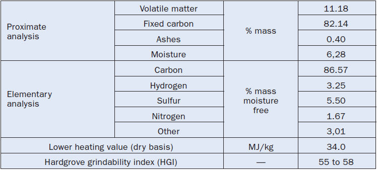
The characteristics and properties of petcoke are closely related to its origin, both in geographical terms and the refinery itself. Just like any other fuel of fossil origin, the characteristics of the deposit determine its components. The refinery is responsible for the profile of the refining process, which determines the final characteristics of the by-product, the petcoke. Thus, the composition and the properties of petcoke vary around a broad range. At this point, there is no classification for petcoke, as we find for coal, that could help define narrower ranges for its proper-ties and composition. Whenever a petcoke is going to be used, it is necessary to have within reach its effective data of origin, obtained through a specific table clearly stating its “origin” as in Table 2.5.8 that shows the characteristics of a United States petcoke exported through the port of Corpus Christi in Texas.
Table 2.5.8. Data of an American Petcoke (Shipped at Corpus Christi, Texas)
Petcoke in Cement Manufacturing
Bearing in mind that the share of petcoke in the cement plants’ energy matrix is growing, and that this chapter focuses mainly on this industry, some specific remarks about the use of such fuel in cement kilns and calciners are in order:
• Petcoke is always used as a pulverized solid in the main and secondary burners, i.e., in the kilns and calciners.
• From the point of view of combustion, the main difficulty in firing petcoke is linked with its low content in volatiles. The flame shape control – a parameter of great significance in cement kilns, because it is associated with the quality of the clinker – is obtained only through igni-tion control. Petcoke flame tends to be “longer” than oil or coal flames, both because of igni-tion delay and because of the time needed for the consumption of the particles in the pulverized fuel cloud injected into the kiln. In a cement kiln, a longer flame brings negative implications to the production process, namely:
■ Produces the worst granular conditions.
■ The formation of larger crystals than those formed under a short flame, with impact both on the consumption of electric power for milling and on the characteristics of strength of the cement.
■ A trend toward the formation of combustion rings inside the rotary kiln, thus making it difficult to reach stabilization of process operations and control.
■ A greater volatilization of sulfur compounds in the firing zone with a possible formation of incrustations in the preheater, and formation of sulfur rings in the kiln.
• To obtain the minimum satisfactory conditions for firing and controlling the flame, petcoke should be milled to a granulometry matching retention from 2% to 5% of the fuel mass sample on a mesh # 170 (0.088 mm). For an efficient firing of coal, for instance, this retained percentage is between 10% and 18% according to the content of volatiles, moisture, and ash.
• An important factor in the economic point of view is the hardness of petcoke because a
“controllable” combustion requires a finely milled fuel and also that:
■ For the same final granulometric condition of a fuel, the cost of energy during milling –and, therefore, the cost of the process itself – is higher, for harder fuel; and the performance of the grinder – i.e., its milling capacity – also decreases with the harder fuel.
■ Petcoke hardness, just like that of any other solid fuel, is characterized by the HGI (Hard-grove Grindability Index) parameter that varies inversely with the hardness of the fuel.
■ Petcoke that usually is used as a fuel shows an HGI between 40 and 55; as a scale reference, HGI 30 implies a very hard solid fuel, while HGI 70 designates one which is very soft.
■ Since petcoke is used mostly to replace coal, which has an HGI between 40 and 60, this replacement implies a compulsorily “review” of the milling system not only because petcoke is in general harder than coal but because it is necessary to crush it more finely due to its lower content of volatile material.
• It is possible to state about the emissions of NOx resulting from the firing of petcoke that:
■ With all other conditions in the process remaining unaltered, the replacement of coal by petcoke does not significantly change NOx emissions.
■ Petcoke usually shows a higher content of nitrogen than fuel oil and, therefore, NOx emis-sions tend to become a little higher when it is used to replace oil.
■ Petcoke produces smaller emissions of NOx when replacing natural gas because, the natural gas may have a considerable content of nitrogen per unit of energy, and that due to its lower emissivity, natural gas flame keeps nitrogen and oxygen under high temperatures for longer periods, a condition that favors the mechanisms that form thermal NOx.
• Petcoke is a fuel that can contain a considerable amount of sulfur; however, its firing in a cement kiln:
■ Does not necessarily involve operational problems provided there is an efficient control of the “sulfur cycle,” so as to guarantee the purge of sulfur by the clinker in the form of alkali sulfates and calcium sulfate. This is a control over the composition of the raw material, and over the flame shape and the kiln thermal profile, as well. A shorter and narrower flame gives chance for a sulfur purge by the clinker because it reduces the volatization of alkaline sulfates and CaSO4 decomposition in the firing zone.
■ It does not necessarily result in high emissions of SOx, because in cement kilns, the increase in fuel sulfur content is not reflected in a proportional increase in SOx emissions. Even though the clinker does not capture all of the sulfur, only a fraction of the fuel sulfur reports to the flue gases and is emitted into the atmosphere.
■ It may impact positively on the cement physical and chemical characteristics, provided there is an efficient control of the sulfur cycle, for instance, improving the initial strength and reducing the setting time without the extra need to add CaSO4 as gypsum into the clinker.
• Exposure to petcoke (green) involves health hazards linked to the irritating effect that it may cause to the eyes, to the skin, and to the respiratory system, both because of its abrasive nature (mechanical effect) and because of the presence of PAHs (chemical effect). The presence of PAHs requires special handling care for the fuel, such as the installation of local exhaust systems and filters in the areas where fuel is transferred, because PAHs are potentially carcino-gens, although no human health effects due to petcoke have yet been described.
• The risk of fires and explosions is very low with petcoke, but a growing risk depending on the content of volatile matter in the petcoke.
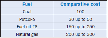
A last remark about the use of petcoke as fuel – its market is not sufficiently stabilized yet and as a consequence prices show some sensitive fluctuations even for a product with well-defined charac-teristics. Table 2.5.9 demonstrates some typical values for 2002. Despite this “disequilibrium” in the market, among all “classical” fuels used by cement plants, petcoke is still the energy input of least relative cost in terms of energy unit released during firing, as shown in Table 2.5.10 which lists and compares this cost as a percentage of the cost of such a unit of energy for a certain type of coal.
Table 2.5.9. Typical International Prices for Petcoke

Table 2.5.10. Comparative Cost of the Energy Unit for Various Fuels
ALTERNATIVE FUELS
“Alternative fuel” is defined as the energy input developed and/or produced specifically to replace a fuel traditionally used in an application or for a new use of a “classical fuel” in other areas of serv-ice. This is the case, for instance, of biodiesel, an alternative fuel that is made of biomass, used vegetable oils, and fat wastes.
There is no fuel, at least not in a significant level and in global terms that, according to this defini-tion, may be labeled as “alternative” for the cement industry. Some kinds of biomass which are fired in cement kilns, such as rice husk or peanut husk are not exclusively produced for this purpose and, therefore, are more appropriately considered “waste fuels.”
WASTE FUELS
A “waste” or residue may be defined and understood in various ways. In 1996, for instance, the Waste Forum established that “the word waste only describes a situation, a transition phase in the life-cycle of a certain product/material that corresponds to its passage from its condition as an element necessary to a continuance of a determined objective into a state of no longer being needed by the manufacturer of this same product,” which gives room for understanding that “waste” is a material not fully utilized, still susceptible to being valued, or in need of total elimination. This defi-nition is the most coherent and encompassing. Some authors also identify these as residual fuels and fuel wastes. According to this point of view, the concept of “waste” in combustion, in this chap-ter always called “waste fuel” or simply “waste” no matter its origin, is closely linked to the economic period and conditions, and can be understood as the unavoidable “leftover” from another activity that has no significant energetic value in a certain social and economic scenario and from a market-ing point of view.
The use of waste fuel by cement plants is a common practice called co-processing, increasing in popularity because it provides four gains simultaneously:
• Reduction of cement production costs because the price for each unit of energy released while firing a waste is far below the price of a “classical fuel.”
• Preservation of fossil fuel reserves.
• Reduction of the volume of waste deposited on landfills and of waste that is burned.
• Decrease in the global greenhouse effect based on a Life Cycle Analysis (LCA), as shown in Figure 2.5.15, because there will be no double emission of CO2.
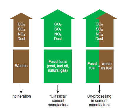
Figure 2.5.15. Co-processing in cement manufacture and global greenhouse effect reduction.
These four gains are very interesting for cement plants because they reduce costs, increase compet-itive advantage, improve social image, and bring economic and environmental benefits to society. Cement plants may benefit from the advantages resulting from the firing of waste, because calcin-ing rotary kilns have very favorable technical conditions for promoting the use of waste fuel with-out damage to the final product, and without jeopardizing the environment.
• The temperatures in the cement kiln, usually reaching 1700°C, are considerably higher than the minimum waste firing temperature established by environmental regulations – 1000°C in general or 1200°C for halogen wastes or those containing PAHs.
• Long residence time of products under high temperature combustion, for dry-process kilns; approximately 3 seconds at temperatures greater than 1200°C, and about 5 seconds at temper-atures between 850°C and 1200°C, far exceeds the minimum period of 2s required by environ-mental regulations.
• The alkaline conditions inside the cement kiln absorb most of the acid gas resulting from the oxidation of sulfur and chlorine, during the firing process.
• The great majority of the non-fuel compounds present in waste – metallic oxides, for instance
– do not harm the production of clinker.
• Most of the metals found in the waste are either amalgamated into the clinker or retained in the dedusting system at the kiln exit; cement kilns are invariably equipped with efficient dedusting systems that will require only minor investments to be adjusted for firing waste.
These considerations show the technical variability of co-processing in cement kilns, provided the firing is carried out under conditions guaranteeing total efficiency of combustion and total param-eter control which, in general, demands customized combustion systems. If this condition of effi-ciency is not met, problems associated with the quality of the product and/or environment protec-tion may occur, totally nullifying the economic gains. If this premise is met, however, the feasibility of waste firing will be conditioned to economic factors that can be determined only after a case-by-case analysis. The replacement, even if partial, of a “classical fuel” by a “waste” always involves investment costs associated with the adjustment or replacement of a burner, the implementation of waste delivery, waste storage, waste distribution systems, etc.
It is important also to highlight that the firing of waste in a cement kiln should always come after another very important stage: the preliminary preparation of the material. This conditioning is usually carried out by specialized companies that collect the waste at the producing source and prepare it at a specific treatment plant for use as fuel in a cement kiln. At the treatment plant, waste is analyzed, classified, and stored for stabilization purposes; later, a “blend” is prepared, so that the material is delivered to the user with its physical and chemical characteristics more or less stabilized. All this preparation is necessary because the waste, even when coming from the same source, does not have by its own nature “stable” characteristics for longer periods of time; the
“blend” corrects this.
It is possible to fire efficiently a great variety of wastes in cement kilns with a thermal replacement rate that can reach up to 50% of the burner capacity, by keeping these premises in mind:
• Previous preparation of waste.
• Final conditioning of waste before firing at the cement plant, for example:
■ Shredding solid waste to obtain granulometry compatible with the kiln injection condi-tions.
■ Heating of liquid waste to improve its flow conditions and to facilitate nebulization for combustion.
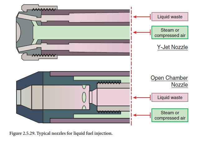
• The use of firing systems specifically designed for the fuel “mix” that is being used. Such firing systems need to have great operational flexibility, to permit the kiln system to absorb the vacil-lating characteristics of a waste fuel without causing adverse effects in the product, in the kiln, or in the environment.
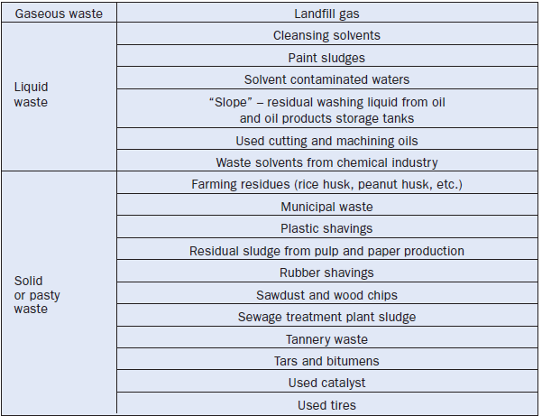
Currently, solid, liquid, and gaseous wastes, whether or not classified as environmentally hazardous, are fired in cement plants with total success and with destruction rates that exceed 99.99999%. Table 2.5.11 lists different types of waste that have been used successfully as fuel in cement kilns.
FUELS IN THE CEMENT INDUSTRY
This chapter has already introduced the general characteristics of the main fuels. The next sections will focus on how these fuels are deployed in the cement industry.
Fuels rank among the major inputs for the production of cement, and they are used in many stages of the manufacturing process in different percentages according to the process and the characteris-tics of each plant, as shown in Table 2.5.12.
Table 2.5.12. Fuel Consumption in Cement Plants
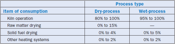
Every plant is unique in its location, the characteristics of raw materials, its access to inputs, and its market share. All these factors, in turn, help to define the kind of fuel used by each plant. Sometimes the fuel used is not the best for clinker production. Cost and environmental impact are not priority issues, either. It is only after an examination focused on weighing all the parameters of importance using the “triangular balance” that a cement plant can reach a solution that best meets the combined requirements of its process. In this manner, the optimum fuels can then be selected.
THE USE OF SOLID FUELS
Solid pulverized fuels are most frequently used by the cement industry. Two fuels actually meet the needs of cement plants:
• Coal, which in global terms is the most widely used fuel by the cement industry. Bituminous coal ranks first in preference, followed by subbituminous coal and lignite.
• Petcoke, whose share in the cement production energy matrix grew significantly in the last 10 years.
The following subtopics in this section will briefly introduce the main parameters that should be met for an efficient use of solid fuels, and the most commonly used arrangements and resources used by the cement plants to firing these fuels efficiently.
Preliminary Conditioning
Solid fuels must pass through a preliminary conditioning before they are introduced into a combus-tion chamber so that efficient firing is obtained. This includes milling and drying under specific facilities. The combustion chamber in a cement plant is mainly the kiln or the calciner. In some cases it is the chamber that generates hot gases for raw materials or for cement additives dryers.
The facilities for a preliminary conditioning of solid fuels introduce a significant investment cost, varying between 12% and 18% of the total investment cost for a cement production plant. In addi-tion, the firing of pulverized solid fuels requires investments such as the installation of dust collec-tion and classification systems, and pneumatic conveying systems. This is all translated into costs. The firing of solid fuels also implies specific and considerable operational costs with the additional consumption of electric power (30 to 60 kWh/ton of fuel), the maintenance of conditioning instal-lations, dust collection, and transportation.
Despite the higher investment and operational costs, solid fuels are widely used by cement plants because when the energy unit released during firing is considered, they have the most economical purchase price per unit energy, in the spectrum of all energy options available to the plant.
As a rule of thumb, pulverized fuel is pneumatically injected into the chambers; a conveying air flow draws the particles inside a pipeline up to the burner inlet nozzle. The injection into the combustion chamber may eventually be carried out with the use of a sheer tube. The use of specially designed burners that incorporate state-of-the-art combustion technology certainly is a much superior solution. This provides firing efficiency and the possibility of using combustion as a process tool which becomes part of the cement manufacturing process.
At the cement kiln burners, a fraction of the combustion air is injected through the burner itself; this is called “primary air.” Primary air includes both air used in pneumatic conveying of pulverized fuel and other fractions usually called “shaping air.” The remaining combustion air is introduced into the chamber coming from the clinker cooler in a preheated condition and is called “secondary air.” It flows around the burner and mixes with the fuel flow and primary air. Recent-generation burners are designed to work at a relatively low primary air rate (a ratio between primary airflow and stoichiometric airflow), either to control NOx emissions or to improve the energy consumption of the kiln. Lower primary air ratios mean a better use of preheated secondary air and, therefore, imply a smaller consumption of fuel for the same clinker production. Figure 2.5.16 shows the advantages obtained with the use of preheated secondary air, comparing the flame adiabatic temperature – i.e., the maximum temperature reached during combustion – of a bituminous coal as
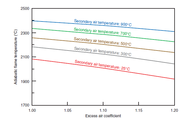
Figure 2.5.16. Adiabatic flame temperature for a bituminous coal
• moisture: 1% wet basis
• primary air rate: 10% of stoichiometric
• combustion products dissociated
• ambient air temperature: 25°C
a function of the excess air coefficient (a ratio between the actual combustion airflow and the stoi-chiometric airflow) and of the preheating temperature of secondary air. If solid fuels demand previ-ous conditioning for efficient use, it is important to introduce in very broad lines what and how characteristics of fuel are changed through milling and drying; the major ones may include:
Milling/particle size distribution. The size of solid particles that are being fired in combus-tion chambers is extremely important for the combustion process and the feasibility of its control. As a general rule, the useful life of a particle of any fuel is proportional to the square of its average diameter, chamber temperature and oxidant availability remaining constant; this rule is called the “D2 Law” and makes possible the following conclusions:
• Large size particles take a longer time to burn and, therefore, need large size combustion chambers, so that the residence time is at least equal to the time needed for complete burnout. Should the combustion chamber size be scanty, a fraction of the fuel will probably leave the chamber unused, thus reducing the efficiency of the process.
• Small size particles fire more briskly and require smaller chambers.
Using fuel milling, it is possible to obtain particles with sizes that match their efficient deployment in any equipment. The product of milling is not uniform-sized particles; particle size varies char-acteristically around an average value. That is, milling predominantly yields particles with sizes that can be categorized according to ranges of values, and particles with very large or very small sizes are rare. The fineness is expressed as the percentage in mass of a sample that is retained in a 170-mesh screen that shows a grid with 0.088 mm clearances. A solid fuel with 15%R170 fineness means that 15% of the mass of a sample is retained by a 170-mesh screen.
The milling system should be compatible with the fuel used so that particles produced have the actual size to meet the requirements of an efficient firing for this fuel. As a comparison, it can be stated, for instance, that bituminous coal does not require as extensive size reduction as petcoke, i.e., bituminous coal burns efficiently when even when coal particles are generally coarser than those of petcoke. Figure 2.5.17 shows a typical granulometric distribution of coal particles produced by an open-circuit ball mill on a chart that shows, on the “y” axis, the cumulative percent passing a given mass sieve, and on the “x” axis, the particle diameter. This coal would be catego-rized as having 10%R170 fineness.
Granulometric requirements should be established according to the content of volatiles in the fuel, the ash content, the moisture content during injection into the chamber, and finally, specific conditions involving size, temperature, and turbulence in the chamber. For coal injection into cement kilns, it is common to establish fineness according to the volatile contents in fuel using the following empirical relationship:
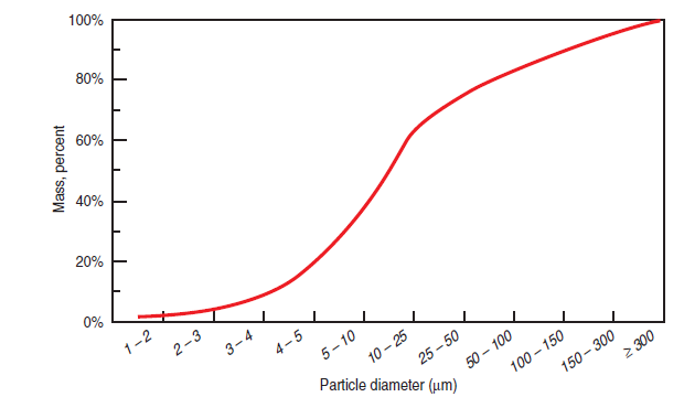
Figure 2.5.17. Typical particle size distribution of pulverized coal from an open circuit ball mill.
where %R170 is the percentage in mass of the sample retained on a 170-mesh sieve and %VM is the volatile content of the fuel used during injection. Although this relationship may be applied to most bituminous and subbituminous coals and to lignite, it has restrictions, and cannot be applied to anthracite or petcoke without reservations. Restrictions also apply to its application to some wet process or white cement kilns, where the secondary air temperature is relatively low.
![]()
![]()
Drying/moisture content. The moisture content of a pulverized fuel is very important at the initial stage of combustion, because the increase in temperature of fuel particles, release of volatiles, occurrence of pyrolysis, and volatilization of fixed carbon only occur after drying. Therefore, the injection of fuel that is milled properly but has residual moisture, will delay the ignition of the cloud of particles, and will make it difficult to control combustion, bringing adverse consequences to the process. Usually, the moisture content of pulverized fuels is specified so that it remains in a range between 0.5% and 2.0% on a wet basis by mass. Very low moisture content is not recommended because of the difficulty in igniting, since there will be a low concentration of OH radicals during the ignition process.
The drying process for fuels usually occurs at the same time fuel is milled. To achieve this, air-swept mills of different types are employed, such as ball mills, tube mills, roller mills, or bowl mills. In these types of mill a permanent hot airflow passes through the equipment at the same time that milling occurs, and this hot airflow sweeps away milled particles, drying them in the process. The hot air used in the drying process is usually obtained from the clinker cooler, and whenever necessary it is mixed with fresh air to obtain a flow at the appropriate temperature. The temperature of hot air at the mill inlet is usually around 150°C to 250°C, whereas the outlet temperature of the air and of the pulverized fuel should be around 65°C to 85°C. This drying arrangement runs satisfactorily for fuels with an initial moisture content of up to 12%.
Sometimes, though, the moisture content of the solid fuel is so high that it is necessary to carry out a predrying step. It is common in these situations to use rotary dryers with parallel flows of raw(nonmilled) solid fuel and combustion gases, the drying agent. Gas admission temperatures in these dryers are maintained, if possible, below 400°C to limit risks of firing and explosions, and the usual gas exhaust temperature remains around 100°C to 120°C. Predried fuel leaves the equipment usually at a temperature between 60°C and 80°C.
Classic Configurations for the Use of Solid Fuels
To obtain proper firing of a solid fuel in a cement kiln or calciner, the fuel must be dried, milled, and transported. There are many arrangement possibilities for carrying out these interconnected operations. Actually, any existing arrangement may be classified into one of the four classical configurations of “firing systems,” a denomination widely accepted by the cement industry, although the burner – the main component of a firing system – is not included. These classical systems of firing – direct firing, semidirect firing, indirect firing, and semi-indirect firing – and their main characteristics are presented below in simplified functional charts.
Direct firing system. The simplest of the four classical configurations, its main characteristics are presented in Figure 2.5.18. The entire airflow passes through the mill and draws the fuel parti-cles toward the burner, where it is injected as primary air. This volume of air (determined accord-ing to the needs of the drying process) and the amount of fuel extracted from the mill are relatively high; therefore, the direct firing system results in high flows of primary air at a relatively low temperature. This high volume of primary air considerably restricts the use of the preheated secondary airflow. Consequently, the direct firing system brings about a lower thermal efficiency or higher specific consumption of energy, when compared to other systems.
The volumes of primary air in direct firing systems usually fluctuate between 25% and 35% of the total combustion airflow; there are instances, though, when this figure reaches 40%. It must be highlighted that in direct firing systems:
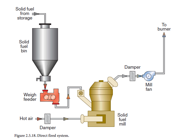
• There are few resources to adjust combustion conditions and to control the clinker produc-tion process.
• Fuel is metered at the access to the mill and henceforth all the fuel is fired in a very short period of time.
Semi-direct firing system. This is a variation of the direct firing system in which negative aspects have been minimized. An outline of the semidirect system is shown in Figure 2.5.19, where it is possible to see the recirculation of air in the mill. This recirculation maintains the minimum airflow needed to draw the particles of the solid fuel, facilitating a reduction in the primary air volume in the combustion system to values between 20% and 30%. If initially moisture content of the fuel is too high, it is necessary to reduce the air recirculation rate in the system; otherwise, the appropriate level of drying that produces an efficient firing of the pulverized fuel will not be reached because of the saturation of the atmosphere inside the mill. In this situation the perform-ance of the semidirect system is similar to that of the direct system.
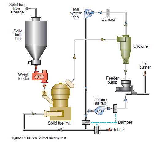
In the semidirect system, it is feasible to reduce the primary air volume by employing recirculation. Also, there is the possibility of running the burner with two fractions of primary air: the conveying air itself coming from the mill and an extra fraction of fresh air supplied by a relatively high-pres-sure fan, just as shaping air. The systems with this feature provide greater flexibility to the opera-tions for the production of clinker and are sometimes called “Hybrid Systems.”
Indirect firing system. In the indirect firing system, as outlined in Figure 2.5.20, there is a separation between the milling circuits and solid fuel injection. Therefore, it is possible to use a single mill to produce pulverized fuel for different combustion systems. The main burner and the burner at the calciner are good examples. This is one of the main reasons why the indirect system has been adopted as a standard by the most modern cement plants.
The indirect system usually employs recirculation of gases through the milling circuit, and the exhaust gases pass through bag-type dust collectors before they are discharged into the atmos-phere. It is also possible in this system to promote the recirculation of gases free of particulate matter which is favorable to mill operation performance, maintenance, and safety.
Milled solid fuel is stored in this system for short periods of time before it is fired. It is necessary, therefore, to provide metering equipment and a flow measurement device downstream to the stor-age silo for each consumption point supplied by the system. Additionally, this configuration enables a shutdown of the solid fuel mill for short periods of time without jeopardizing kiln opera-tions or other users of pulverized fuel.
The indirect system accepts the use of conveying air with reduced flows, that together with shaping air can be used with recent generation burners. These burners run on a reduced primary air rate (between 7% and 12% of stoichiometric air) and have high operational flexibility that provides a reduction in the specific consumption of energy by increasing the use of preheated secondary air and help maintain low emissions of NOx,contrary to results achieved with conventional equip-ment.
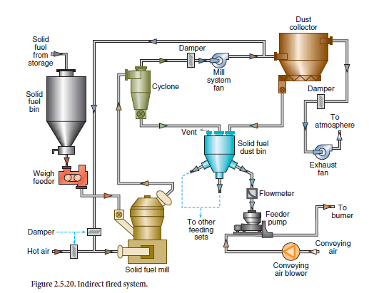
The indirect system has two disadvantages,:
• The need for extra equipment, i.e., a dust collector and a silo that are risk factors, where fires and explosions may occur.
• Higher installation costs, because of the use of the dust collector and silo, and the need for a metering system and its peripheral equipment that can add a high degree of sophistication to the process and, therefore, a very high cost.
Semi-indirect firing system. This system is a simplification of the indirect system in that the pulverized fuel storage system is eliminated and the metering system may eventually be discarded as well. Consequently, this system can only be used to supply a sole consumption point. In practi-cal terms, the semi-indirect system has a very restricted application and its current use at cement plants is quite rare.
Mills for Solid Fuels
To provide an efficient firing of solid fuels – especially for coal and petcoke, the “classical fuels” – it is necessary to have them pulverized before injecting them into the combustion chamber. Therefore, the mills perform a significant role in providing favorable conditions for solid fuel firing. The mills are generally integrated into the combustion system according to two circuit designs – open circuit and closed circuit. In the open circuit, the mill receives only raw fuel. All dust particles resulting from the milling process are carried by the gases that flow through this equipment and are conveyed to a storage silo or directly to the burner. Whereas in the closed circuit, the gas flow leaving the mill and carrying along the pulverized solids goes through a device called a classifier or separator, that sends the larger particles back to the mill, while the gases with finer solids pass through and go to a storage silo, or go directly to the burner. Here, it is important to highlight the closed circuits that:
In this configuration, the mill receives raw fuel and the material captured by the classifier, and a “final milling product” having narrow particle size distribution is obtained with a low concentration of large particles, which is favorable for combustion.
Many types of classifiers are available, there are static classifiers with a fixed geometry, or adjustable geometry using deflecting blades; there are also dynamic high efficiency separators. Between these are traditional dynamic classifiers and mechanical separators. The more modern and sophisticated the equipment, the more accurate the cut; i.e., the less likely it is that the final product will contain a particle larger than a predefined value. There will be a high incidence of particles whose sizes are very close to, or even below, such a value.
The types milling equipment preferred by cement plants include:
• Bowl mills
• Roller mills
• Ball mills
Bowl mills are more efficient with respect to electric power consumption, because they require only between 10 and 18 kWh/t of product, whereas ball mills require between 30 to 50 kWh/t of product. These figures are basically dependent on the fuel hardness (HGl) and the expected fine-ness of the final product.
Roller and bowl mills occupy less space, permitting more compact arrangements compared to ball mills.
Ball mills are robust, but they need longer downtime periods for maintenance. Ball mills are particularly appropriate for processing certain types of coal, because there is the possibility of having separate chambers for drying and milling.
Other types of mills, such as hammer mills or impact mills, are rarely used by cement plants because of the high consumption of energy and high wear rate of their parts. This high wear rate also influences performance with respect to fineness and productive capacity during an operation campaign.
Solid Fuels Dosing Equipment
Dosing equipment is essential for the performance of pulverized solid fuels combustion systems, and it is mandatory to have mass flow metering.
The regularity and accuracy of use within the strict limits that the process requires demand equip-ment of high reliability. Since cement kilns should run with reduced excess air rates, the presence of dosing fluctuations may cause “CO peaks,” i.e., a very high emission of CO if the flow of fuel suddenly exceeds the value accepted by the process.
The vast majority of direct and semidirect firing systems use belt weighfeeders that have the following characteristics:
• Belt weighfeeders for direct and semidirect firing systems are positioned upstream to the mills and provide metering of moist raw fuel. It is necessary, therefore, to have frequent monitoring of the moisture content at the input to carry out all the necessary adjustments of flow and maintenance of the kiln thermal conditions as well.
• These systems should be specified and designed to avoid the accumulation of dust through the pulverized fuel conveying circuit, so that a steady-state operation can be guaranteed and the flow of raw fuel that is conveyed is equal to the flow of pulverized fuel produced at any instance.
• Belt weighfeeders are basically made of a relatively short conveyor belt driven by a variable speed motor, partially supported by articulated joints and partially by a load cell. In this equipment, the mass flow of conveyed material is proportional to the product load (measured by the load cell) times the angular speed of the driving motor. If there is a fluctuation in the load information, an automatic correction of driving motor speed will take place to maintain the constant mass flow of the fuel needed.
There is a wider range of alternatives for metering equipment associated with indirect firing systems. Since dosing in indirect firing systems is for pulverized fuel, special care is needed to prevent firing hazards and explosions. The use of explosion-resistant equipment (pressures up to 10 bar) is highly recommended for these configurations.
Loss-in-weight was another system principle employed by cement companies in the past. Many of these systems are still used today, decades after they were installed. There are some considerations about them, namely:
• A loss-in-weight system includes a storage silo at the bottom of which a metering silo is coupled. This metering silo is supported on load cells and comes with an extractor device, usually a screw conveyor, with variable speed, and that is an integral part of this metering silo. Both the loading of this metering silo and the unloading of the extractor device are intercon-nected to the fuel circuit through flexible elements that prevent the transmission of external forces to the load cells.
• A loss-in-weight system runs through a permanent adjustment of the angular speed of the extractor, so that the variation rate of the weight of the whole set (metering silo and its pulverized fuel load + extractor) remains constant all times. As the pulverized fuel is consumed, it is necessary to refuel the metering silo from the storage silo. This operation is carried out at a fixed angular speed of the extractor according to the last value deployed before refueling, followed by opening the throttle valve that allows a quick filling of the metering silo. Once this silo is refueled, the valve closes and the system resumes its operation, adjusting the angular speed of the extractor to the rate of variation of the weight of the whole set.
•A loss-in-weight system requires the use of a special device to introduce fuel into the convey-ing airflow and prevent it from spilling over into the silos and affecting the metering. This device is usually a rotary airlock or a solid fuel pump.
There are currently two systems employed by cement plants for metering solid fuels for indirect firing systems:
1. Rotor weighfeeder system
2. Coriolis system
The rotor weighfeeder system runs through the variation of the angular speed of a vertical axis multi-chamber rotor that continuously removes pulverized fuel from a silo, introducing it directly into the conveying airflow.
• The vertical axis rotor is placed in a specially built casing that provides the means for sealing its several chambers.
• The casing with the vertical axis rotor is simultaneously supported over articulated joints that are aligned with the nozzles supplying pulverized fuel, nozzles that supply conveying airflow, and that unload air/dust and over a load cell.
• The geometrical arrangement of the components is made so that the load to the cell is propor-tional to the mass of pulverized fuel saved up in the rotor cells, and the result of this value times the angular speed of the rotor is proportional to the fuel mass flow. Thus, the equip-ment panel shows and controls the mass flow providing the necessary adjustments to the rotor angular speed.
The Coriolis system runs based on the so-called “Coriolis Principle” that is studied by the dynamic of systems and has among other uses application in inertial navigation systems and ballistics. The Coriolis system is essentially made of two interconnected pieces of equipment. One piece provides the extraction of the pulverized fuel from the silo, and the other piece measures the mass flow of fuel. This is the equipment that actually employs the “Coriolis Principle” of measuring the mass flow as follows:
• There is a rotary extractor below the pulverized fuel silo, whose angular speed is adjusted through the variation of frequency at the electric input of its driving set.
• The material extracted from the silo is dumped onto the mass flow-measuring device.
• The mass flow-measuring device is made of a rotary disc whose angular speed is kept constant and which is provided with a torque indicator. Thanks to the “Coriolis Principle,” it is possible to correlate the material mass flow that falls over the rotary disc and the torque applied on its axis to maintain a constant speed.
• The electronic control system commands the extractor angular speed, so that the torque on the axis of the measuring device is kept constant, i.e., the pulverized fuel mass flow is kept constant.
The metered material falls directly onto the conveying airflow after passing over the rotary disc. In the Coriolis system the seal necessary to prevent conveying airflow leakage is furnished by the pulverized fuel column itself found inside the silo. This is the reason it is necessary in this system to always keep a minimum amount of pulverized fuel stored in the silo.
Solid Fuels Other than Coal and or Petcoke
Coal and petcoke are the most common solid fuels used in cement kilns. The increase in the use of residual solids by cement plants has also been mentioned. These fuels can have a very reduced cost and in many cases the cement plant may collect revenue by firing such residues. It has also been said in this chapter that rotary cement kilns are combustion chambers with very high temperatures with respect to incineration, and their residence time is relatively long. It should not be over-looked, though, that the first and main objective of such kilns is the production of a good quality clinker without damage to the environment. The firing of significant amounts of solid residues in cement kilns is, therefore, always contingent upon two factors: the quality of final product(clinker), and impact on the environment.
Prior to its use in firing, a solid residue should always be analyzed for its chemical composition with respect to its compatibility with the cement plant raw materials and the nature of the produc-tion process. However, because of the economic importance and the plant-specific nature of utiliz-ing such residues as fuel, the following general remarks are also worthy of notice:
• For wet process, long dry process, and dry process kilns with suspension preheaters, it is highly recommended that the injection of fuels be carried out through the main burners. This injection method ensures that 1) the residues pass through the kiln region with the highest temperature where the availability of oxygen is good and the level of turbulence is sufficiently high to guarantee enhanced mixing and to speed up reactions of decomposition and oxida-tion, and 2) both in the solid injection phase and the gas phase resulting from its decomposi-tion, the most favorable conditions for efficient combustion are present for a relatively long period, thus providing conditions that are conducive for maximized use of such fuels.
• The solid residues that show better results when injected through the main burner include: saw dust, wood chips, plastic shavings (provided the plastic is chlorine-free) and a mix of paper, cardboard, textiles, and plastic.
• Often times in suspension preheater kilns, the solid residues are fired in the smoke chamber. This is a relatively simple method of introducing the solid residue into the process. Contingent on the amount of residue used, favorable outcomes or adverse outcomes, such as a distortion of the kiln thermal profile, lack of control over the sulfur cycle, buildups, emissions of CO and VOCs, etc., may occur.
• A special emphasis should be given to the possible use of whole tires as a residual fuel. Currently a large numbers of used tires represent considerable environmental and public health hazard. The cement industry can be a great asset for processing and disposal of tires. Nevertheless, major technical difficulties that prevent the firing of tires in cement kilns include.
■ Process wise, it would be better to have chopped tires fired in the kiln. But this procedure of “size reduction” has inherent difficulties mainly associated with 1) the capacity of equip-ment to chop tires, 2) the acquisition cost of tire chopping equipment, and 3) the consump-tion of electric power in the tire chopping procedure.
■ Because of such difficulties, the usual practice in cement plants whenever tire incineration is required is the use of equipment that simply introduces whole tires into the kiln.
■ In wet and long-dry process kilns, it is common to find a device that introduces tires in the kiln mid-length through a folding door that is opened when it reaches the peak of a revolu-tion. Typically, a special installation is used to handle the tires and prepare them to be intro-duced into the kiln at the right moment when the folding door is opened is necessary. Because of the location of the entryway, the tires run for a long distance inside the kiln, i.e., there is a residence time long enough to guarantee the completion of heating, pyrolisis, and gasification stages resulting in total consumption of tires before reaching the product discharge. These kilns are able to fire one tire per revolution. However, the major restric-tions to this process are associated with 1) CO and organic compounds emissions that are not fully oxidized, and 2) the generation of a reducing atmosphere over the material bed inside the kiln with adverse effects on clinker quality.
■ In dry process kilns with suspension preheaters, the most common practice is the use of a device that introduces whole tires into the smoke chamber and makes them arrive quickly at the rotary kiln. In these circumstances the feeding rate may vary between 300 and 1200
kg/h, according to the capacity of the kiln.
USE OF LIQUID FUELS
Fuel oils are among the liquid fuels most frequently used by cement plants. Oil #6 is an industry tradition, and most recently ultraviscous fuels are being used more by the industry. In the last few years the share of liquid wastes such as solvents, paint sludge, used lubricant oils, subproducts of the petrochemical industry, etc., in cement plants energetic matrix has grown considerably. Each of these wastes presents its own peculiarities, and its own storage, handling, and firing requirements.
The price of the thermal energy unit and the cost of implementation of installations for firing operations of fuel oils range through an intermediary level when compared to values for solid traditional fuels and for natural gas. When price is concerned, the use of fuel oil in a cement plant includes, in addition to the fuel purchase cost, 1) the implementation of storage and a system for preparing the fuel oil, not to exceed 4% of the plant total equipment costs, and 2) operational costs
associated mainly with heating, pumping, and the nebulization of fuel, which require additional electric poweAr and/or steam expenses that can be evaluated as follows:
• For installations where heating is obtained through steam, the consumption of electricity varies from 2 to 5 kWh per ton of oil, the former rate being typical of installations using steam nebulization, and the latter of installations using mechanical nebulization. Also, the consump-tion of steam varies from 80 to 250 kg per ton of oil, the former rate being typical of installa-tions using mechanical nebulization, and the latter of installations using steam nebulization.
• For installations where heating is obtained by electric means, the consumption of electricity varies from 60 to 65 kWh per ton of oil.
The use of fuel leads to flame temperatures comparable to those obtained through the use of coal in the same conditions of excess air coefficient and secondary air preheating temperature. Figure 2.5.21 shows the variation of the flame adiabatic temperature of an ultraviscous fuel oil, i.e., the maximum temperature that can be reached during firing, as a function of excess of air coefficient (the ratio between the actual combustion airflow and the stoichiometric airflow) and of the temperature for secondary air preheating.
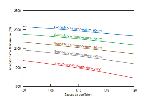
Figure 2.5.21. Adiabatic flame temperature for an ultraviscous fuel oil
• primary air rate: 10% of stoichiometric
• combustion products dissociated
• ambient air temperature: 25°C
Nebulization
Any liquid fuel that needs to be appropriately and efficiently fired must be nebulized during its injection into the combustion chamber in which it will be consumed. It is to achieve nebulization that the liquid flow is converted into a cloud of droplets – hence the name nebulization from the Latin word “nebula,” meaning cloud. The nebulization converts the liquid jet into a cloud of droplets with sizes that vary in a more or less narrow band around an average value. This average value depends 1) on the fuel itself (viscosity and surface tension are the predominant properties), 2) on the pressure and temperature of the environment into which the fuel is injected, and 3) on the velocity of injection.
There are three “classical” methods of achieving high liquid flow velocity and obtaining nebuliza-tion. Relative to these methods, and taking into consideration mainly the firing of fuel oil in cement plants, the following remarks are applicable.
Mechanical nebulization. This method provides the means for the transformation of the dense liquid jet into a cloud of droplets through an increase on the pressure of the liquid fuel by means of a pump and the subsequent injection of such fuel into the combustion chamber with the help of a nozzle that has an appropriate shape and size. It is worth mentioning about the mechani-cal nebulization that:
• To obtain the mechanical nebulization of a liquid fuel it is necessary to increase its pressure, up to a value between 25 and 60 bar, depending on the nature and on the conditions of the fuel – before it is injected into the combustion chamber.
• There are three different configurations for the jet nozzles that make it possible to provide mechanical nebulization of liquid fuels, namely:
■ A simple circuit fixed shape, in which the nozzles govern only the axial velocity of the nebulized jet.
■ A double circuit fixed shape, in which the nebulized jet is a result of the mixture of streams that pass through nozzles that provide axial velocity and of streams that pass through nozzles that provide tangential velocity.
■ A variable shape, in which there is a mobile “needle” inside the nozzles that can be placed forwards or backwards on an axial direction, making it possible to adjust both nebulized fuel flow and velocity.
• The great advantage associated with the use of mechanical nebulization comes from the fact that it can be accomplished by the use of jet nozzles provided with a relatively simple shape that are of easy construction, and therefore cheaper, than the nozzles used in nebulization with auxiliary fluid.
• There are many disadvantages associated with the use of mechanical nebulization, namely:
■ Mechanical nebulization is feasible only with clean liquids.
■ Mechanical nebulization calls for liquid fuels with lower viscosity, which must be preheated up to higher temperatures.
■ Because it is necessary to have liquid fuel at high pressure, mechanical nebulization must have 1) a fuel pumping system with special high-pressure pumps, and 2) fuel distribution pipelines of “600 lbs class” or above, with tubes provided with thicker walls (and therefore heavier and more expensive), and more “robust” and more expensive fittings (valves, flanges, connections, filters, etc.).
■ Because of the high pressures involved, the installations that deploy mechanical nebuliza-tion entail greater potential accident hazards than installations that deploy nebulization with auxiliary fluid.
■ Nozzles used for mechanical nebulization are more subject to clogging than those designed for nebulization with auxiliary fluid.
■ Mechanical nebulization has a low turn-down ratio.
Nebulization with auxiliary fluid. With this method, transformation of a dense liquid jet into a cloud of droplets is obtained through its acceleration by a high pressure compressible fluid –usually compressed air or steam – through nozzles of appropriate shape and size and under appro-priate conditions. It is worth highlighting that nebulization of a liquid fuel with auxiliary fluid is obtained under relatively low pressures of fuel – between 5 and 15 bar. This nebulization method presents three options for auxiliary fluid, 1) compressed air with a pressure between 5 and 7 bar, 2) low pressure steam between 5 and 12 bar, and 3) low pressure-air that in cement plants is supplied by the primary air blower. It is, however, an option that is rarely exercised.
There are three classical geometries for the jet nozzle that accept nebulization of liquid fuels with auxiliary fluid. These are Y-jet, T-jet, and Open Chamber geomateries
.There are many advantages associated with the use of nebulization with auxiliary fluid, namely:
• Nebulization with auxiliary fluid is feasible with dirty liquids.
• Nebulization with auxiliary fluids can be performed with the liquid fuel at higher viscosities which can therefore be preheated at lower temperatures.
• Because nebulization with auxiliary fluid is carried out with the liquid fuel under relatively low pressures, it can be accomplished with lower implementation costs since, 1) the pumping system for the fuel deploys low-pressure pumps, and 2) the fuel distribution pipelines are “150 lbs class” with thinner wall pipes (and therefore lighter and cheaper), and need less robust and cheaper fittings (valves, flanges, connections, filters, etc.).
• Because of the pressures involved, the installations that employ nebulization with auxiliary fluids present fewer potential accident hazards than installations that employ mechanical nebulization.
• Nebulization with auxiliary fluid has a high turn-down ratio.
The major disadvantage associated with the use of nebulization with auxiliary fluid arises out of the need to supply this auxiliary fluid and, therefore, to incur operational costs and investments inherent to its generation and distribution.
Nebulization by emulsion. This method is actually a variation of nebulization with auxiliary fluid. For nebulization by emulsion, a fluid with a higher pressure than that of the fuel is mixed with it and then the mixture – still with separated phases – is forced through nozzles that increase the velocity of the double-phase flow, also increasing its turbulence, thus creating the emulsion(fuel + auxiliary fluid). This emulsion is then injected into the combustion chamber through nozzles that cause its nebulization.
The selection of the nebulization method to be used in a burner depends on the specific character-istics of the fuel. For fuel oils usually fired at cement plants, the chart in Figure 2.5.22 shows the range of applicability of the three methods as a function of the oil heating temperature so that an efficient and controlled combustion is obtained.
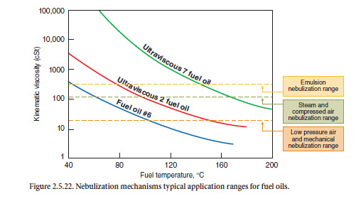
Typical Installations for Liquid Fuel Firing
Different steps from fuel delivery to firing are involved in the combustion of liquid fuels: delivery, storage, pumping, heating, flow metering, flow control, and injection. This full range of steps is not always necessary. For example, if a certain fuel has an appropriate viscosity at room temperature, the preheating step is not required. The recommended practices and technologies that have proved to be more efficient throughout the years in each of the handling steps for liquid fuels are presented here.
Fuel delivery. The liquid fuel usually arrives at the cement plant in tankers or in rail tankcars. Fuel delivery is a handling step that corresponds to fuel transfer from the transportation vehicles to the plant storage tanks. The two most common arrangements for fuel delivery are introduced in Figure 2.5.23: delivery by gravity and delivery by pumping.
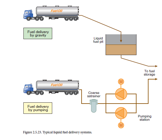
• Fuel delivery by gravity. When the cement plant topographical conditions permit, fuel oil delivery can be made by gravity, directly from the transportation vehicle into the storage tank. It is a system that saves energy. It is obvious that a significant difference between the level where the transportation vehicle (the tanker or the tank-wagon) stands and the top of the storage tank is necessary. Special care should be taken in the pipeline design, so that unloading operations do not stretch for too long a period.
• Fuel delivery by pumping. In these installations, the recommended transfer rate varies between 20 m3/h and 60 m3/h, and the pipeline has tubes with a nominal diameter between 4 in. and 8 in. (100 mm –200 mm). The maximum pressure in these installations barely exceeds 5 bar, and frequently it remains between 2 and 3 bar. These delivery systems are characterized therefore as high-flow, low-pressure systems. For reasons of operational reliability, it is advisable to install two pumps in parallel at these delivery stations, so that while one is running, the other remains as a standby unit. It is also advisable to install coarse strainers on the pump suction lines for their mechanical protection.
The type of pump to be used at the delivery station should be selected taking into consideration the characteristics of the fuel being handled; the information in Table 2.5.13 presents as a reference the initial parameters for the selection of pumps used for the delivery of liquid fuels. Nevertheless, it is necessary to consider the other properties of the liquid on a case-to-case basis. Properties such as volatility and corrosion potential will define required characteristics of the pumps, such as their material of construction, types of seals, angular velocity, the use of a heating jacket, etc. – and the pipeline of the liquid fuel delivery system can also be defined.
Table 2.5.13. Pump Type for Liquid Fuel Delivery Systems
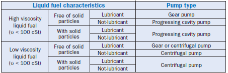
Storage. Liquid fuels at cement plants are stored in vertical cylindrical tanks made of steel. Since these fuels must be maintained under temperatures higher than that of room temperature to facili-tate pumping, storage tanks are provided with thermal insulation on their external surface. To maintain this temperature, storage tanks for liquid fuels are provided with electric or steam heat-ing systems, as shown in Figure 2.5.24. The following remarks concerning liquid fuel storage systems are important:
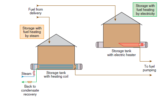
Figure 2.5.24. Typical liquid fuel storage systems.
• Different fuels should be stored in separate tanks. When a cement plant uses several kinds of liquid fuels, there should be at least one specific tank for each kind of fuel.
• Storage tank capacity at cement plants usually varies between 1,000 m3 and 3,000 m3.
• The fuel “strategic inventory” – i.e., total storage capacity – is usually established to support 7to 10 full days of plant operations; to store this “strategic inventory” in big plants, two or three tanks with a unitary capacity falling within the range of the “normal volumes” mentioned in the previous item may be needed.
• The construction and installation of fuel storage tanks must abide by specific rules and regula-tions. American Petroleum Institute (API) and National Fire Protection Agency (NFPA) produce the most important of these rules, identified according to the following key codes:
API – Stand.Spec.12.
API – Standard 620.
API – Standard 650.
NFPA – 30.
NFPA – 31.
• Liquid fuel storage tanks should always be placed inside a “protection dam,” an isolated and diked area able to hold any eventual fuel leakage and prevent it from spilling into the environ-ment. There are two options for placing tanks inside these protection dams:
■ One tank per protection dam – a situation where the free internal storage capacity of the dam is enough to hold the maximum volume that can be stored in the tank.
■ Two or more tanks per protection dam – a situation where the internal volume of the dam should be enough to hold a volume of fuel equal to the sum of ‘a volume equal to the maxi-mum amount that can be stored in the dam’s larger tank, and the volumes of those parts of all other tanks that are above the dam crest.’
• Modern storage installations for liquid fuel no longer employ the “daily tank” or the “service tank,” a smaller reservoir from which the fuel was pumped to the consumption point and to which the fuel was transferred from the storage tank. The use of a service tank increases imple-mentation and plant operation costs without adding any significant operational advantage.
Pumping. For reasons of operational stability, liquid fuel pumping systems usually comprise two pumps installed in parallel, so that while one is running the other is on standby. It is also highly advisable and common to install strainers upstream of the pumps – i.e., on the suction pipeline –for mechanical protection. Pumping stations are characteristically low-flow and high-pressure systems. In cement plants, two typical configurations are used for the pumping system of a liquid fuel, shown in Figure 2.5.25. They are:
• Fixed speed pumping system. This system uses fixed flow positive displacement pumps. The control of the fuel mass flow is obtained through control valves. Downstream from the pumps, a pressure control valve sends back to the storage tank any excess fuel that is pumped but not used.
• Variable speed pumping system. This system uses variable flow positive displacement pumps. The pump driving speed varies in accordance with consumption needs, so it does not have any control valves, nor does it send fuel back to the storage tank.
The capacity of the pumps depends directly on the maximum fuel consumption to be supplied by the pumping station; usually pumps are designed to deliver this maximum flow plus a slight “margin.” The pressure required for discharge is dependent upon three parameters, 1) the kind of liquid fuel distribution facility, 2) pressure drop in the distribution pipelines, including fittings and valves on the circuit, and 3) supply pressure required by the nebulization device; this parameter adds the greatest impact to the pump’s discharge pressure.
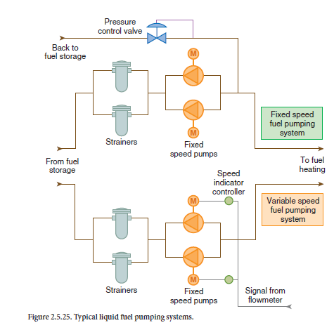
When liquid fuel firing is obtained through nebulization systems with auxiliary fluid, the required pump discharge pressure varies between 10 and 20 bar. On the other hand, when liquid fuel firing is obtained through mechanical nebulization systems, the required pump discharge pressure is considerably higher and can even reach 60 bar.
The kind of pump to be used should be selected according to the characteristics of the fluid being transferred, as well as to pressure levels, as shown in Table 2.5.14 for reference. It is necessary, though, to consider other liquid properties on a case-by-case basis, such as volatility and corrosion potential. These properties help define specific characteristics, such as construction material, types of seals, angular velocity, the use of a heating jacket, etc. for the pumps and liquid fuel pumping station pipelines.
Table 2.5.14. Pump Type for Liquid Fuel Pumping Systems
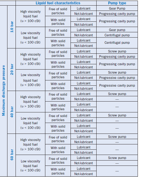
Heating. This step of liquid fuel handling is provided as a means to increase liquid temperature up to an appropriate value to ensure an efficient combustion. This temperature varies from fuel to fuel and is related to properties such as surface tension, viscosity, flash point, etc. Regarding liquid fuels heating systems usually found in cement plants, the following remarks are in order:
• Essentially, there are two configurations for heating systems, both introduced in Figure 2.5.26; they are, 1) an electric heating system, that uses electric resistance to increase the temperature of the liquid fuel flow, and 2) steam heating system that uses a surface heat exchanger with steam as the high temperature fluid to increase the temperature of the liquid fuel flow.
• Whenever there is steam availability on the plant premises, steam heating is preferred to elec-tric heating because thermal energy is “less noble” than electric power – i.e., in terms of savings the cost per unit of energy in fuel heating is cheaper with steam systems than with electric systems.
• Asteam heating system usually employs steam saturated up to 10 bar that provides efficient heating for the liquid fuel to a temperature up to 150°C – enough, for instance, for the condi-tioning of almost all fuel oils.
• If a fuel requiring heating at a temperature above 150°C (such as ultraviscous oil) is fired in plants with steam availability, a “mixed configuration” may be used combining two “classical” heating systems and running in series. For example, when using a steam heating system, liquid fuel tem-perature is initially increased up to 150°C; and the temperature of the preheated oil is increased by an electric heating system until it reaches the final value required for efficient firing.
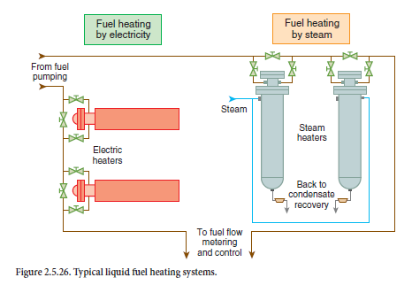
• Some cement plants have steam under a higher pressure, usually 20 bar, which enables steam heating to increase the liquid fuel temperature up to a temperature slightly above 180°C; few plants are provided with this facility, however.
• Whenever the systems use electric heating, it is necessary that the “heat transfer specific rate,”
i. e., the amount of power dissipated by unit area of the surface that the resistance uses to transfer heat to the fuel flow, does not exceed a threshold value that depends on the nature of the liquid that is heated, so as not to produce incrustations on the surface. For liquid fuels commonly used by cement plants, the specific rate of energy release 1) must be kept between 1.0 W/cm2 and 1.5 W/cm2 for fuel oil heating, and 2) must be around 0.5 W/cm2 for ultravis-cous oil heating
• Some cement plants – very few, actually – use a heating system with surface heat exchangers where the hot agent is the so-called thermal fluid. These systems heat the liquid fuel up to temperatures considerably higher than those obtained normally with steam heating.
Flow control and metering. Essentially, there are two systems for flow control and metering of liquid fuels. They are schematically shown in Figure 2.5.27, each compatible with either one or another of the typical pumping systems used in cement plants. The following remarks apply to flow control and metering systems:
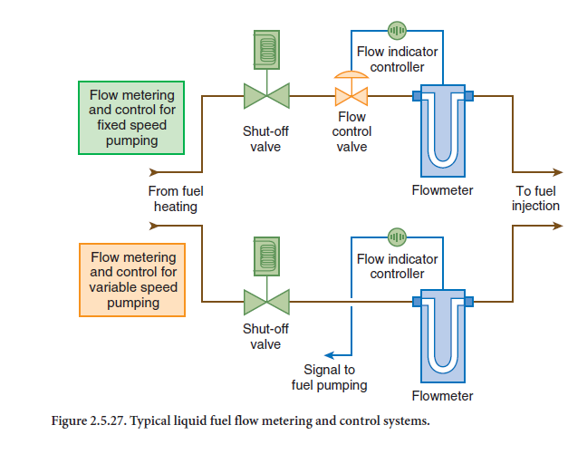
• In the system that is compatible with fixed speed pumping, flow control is obtained through a control valve that is motor-driven or pneumatically actuated, and where opening and closure are determined by a command signal generated by the flow meter.
• In the system that is compatible with variable speed pumping, there is no control valve. The command signal generated by the flow meter is directly sent to the frequency converter of the pump driving motor to adjust the flow pumped to consumption needs.
• Comparing both systems, the one compatible with the variable speed pumping is more economical with regard to electric power consumption. In this system the pump only “drives” a mass of liquid fuel strictly necessary to meet momentary consumption. On the other hand, the system compatible with the fixed speed pumping, “drives” a maximum mass of liquid fuel that can be used; and any momentary “excess” is sent back to the storage tank.
• The flow meter can be volumetric or mass flow meter, in that, the mass flow meters – essen-tially those of the “Coriolis” type – are currently preferred by cement plants because, 1) they add no errors to the accounting of the flow because of temperature variation, and therefore to the specific volume or density, of the liquid fuel, 2) they offer low resistance to the passage of fuel and thus do not introduce a significant pressure loss into the distribution circuit, 3) their accuracy is high, and they are highly reliable, and they have no moving parts and therefore have fewer maintenance problems.
The volumetric meters are positive displacement meters, just like traditional or oval shaped gears, that in the past were frequently used by cement plants and can still be found in old installations. They currently have been replaced by mass flow meters because of their advantages.
Injection. The injection system is used to introduce the liquid fuel into the combustion chamber in a condition appropriate to allow its efficient firing. As it has already been mentioned and widely debated in a previous item in this chapter, the firing of liquid fuels is closely connected to its nebu-lization. Therefore, typical injection systems for liquid fuels used by cement plants, schematically represented in Figure 2.5.28, correspond to the most commonly used nebulization mechanisms. It can be stated about these systems, in addition to what was introduced in the nebulization section, that:
• The injection systems with mechanical nebulization and simple circuit are used with clean liquid fuels, whose properties (viscosity and surface tension) are stable and well determined. The burner is provided with adjustment features for flame shape through primary air.
• The injection systems with mechanical nebulization and double circuit are used when, in the same conditions the mechanism with simple circuit is used, another adjustment feature for flame shape is required. This additional resource occurs thanks to the possibility of a
“balance” between the flows of both circuits, one with axial velocity and the other with tangential velocity.
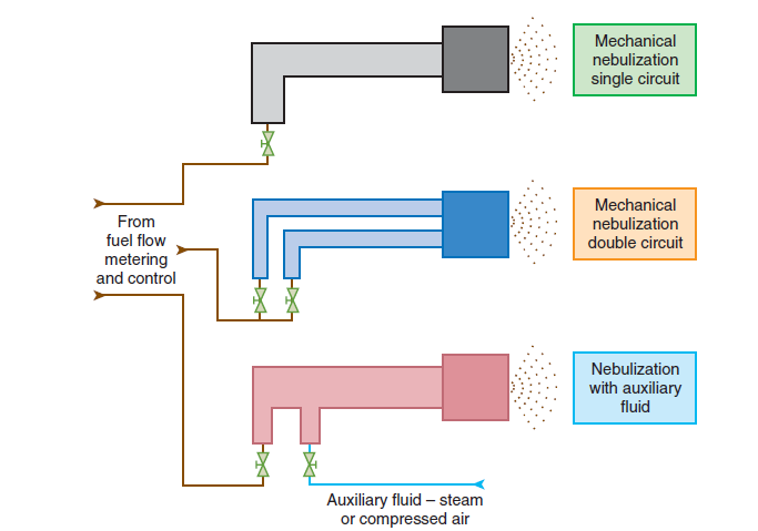
Figure 2.5.28. Typical liquid fuel injection systems.
• The injection system applying nebulization with auxiliary fluid can be used with any liquid fuel – clean or dirty, with stable properties or not. This essentially is a simple circuit system with a second circuit for the auxiliary fluid, usually steam or compressed air. This system can be made available with two variants concerning the auxiliary fluid delivery pressure; the vari-ants include 1) auxiliary fluid delivered at constant pressure, and 2) auxiliary fluid delivered with a pressure differential that is constant when compared to fuel pressure. The system can also be used with different geometries for the injector nozzle: T-jet, Y-jet, and Open Chamber
– the general features of the two last geometries being shown in Figure 2.5.29.
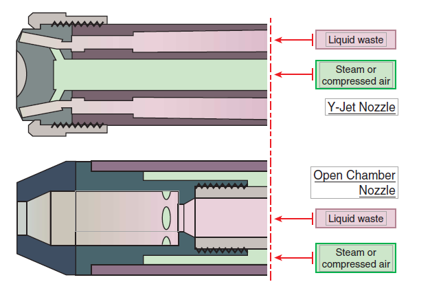
Figure 2.5.29. Typical nozzles for liquid fuel injection.
THE USE OF GASEOUS FUELS
Natural gas is essentially the gaseous fuel used by cement plants, since other gaseous fuels are not commonly used because of supply logistic problems. Gas from landfills, for instance, would only be feasible for a cement plant that is located in the immediate neighborhood of a landfill.
The share of natural gas in the cement plant energy matrix has grown slightly in the past few years. The current trend, as a matter of fact, is for natural gas firing to become a natural and inevitable transition from fossil fuels that are more aggressive to the environment than the clean and renew-able fuels to be used in the future. The following remarks about the use of natural gas by cement plants are in order:
• Among all fuels deployed by cement plants, natural gas is the simplest to use because 1) firing it is easy and efficient, 2) there is no need for any preliminary preparation to firing, and 3) it is not stored at the cement plant since it is constantly made available to the curb by the utility company.
• The facilities for using natural gas at a cement plant should be designed, built, and operated according to safety rules that are quite strict, among which the most significant and frequently applied are:
■ NFPA – rule 86.
■ National Gas Code.
■ Safety requirements established by the insurance companies and translated into procedures usually created by private organizations such as Underwriters Laboratories in the United States.
■ The utility company installation rules that basically establish the minimum requirements based on rules created by other agencies such as ASME, ANSI, DIN, etc.
• Natural gas is delivered by the utility company to the consumer under a pressure between 5 bar and 20 bar at a “delivery point” that is 1) at one end of the take-off of a medium pressure distribution branch the name used in the gas industry to identify the pipes to distribute natu-ral gas under pressures ranging from 5 bar to 20 bar, and 2) located at the cement plant physi-cal boundaries.
• Starting from the delivery point, the facilities for the use of natural gas as fuel by a cement plant include
■ The metering and reduction set, built at the plant boundaries and according to the utility company’s own standards, in which 1) the monitoring of the volume of gas supplied to the consumer company is made, and 2) gas pressure is reduced to a value between 2 bar and
5 bar, a common range of pressures for gas distribution inside the cement plant boundaries.
■ The internal distribution network through which natural gas under a pressure between
2 bar and 5 bar is distributed from the metering and reduction set to the different points of consumption.
■ Gas valve train – one unit for each point of consumption of natural gas, and where 1) the final reduction of gas pressure is made to reach the adequate level for its injection into the combustion chamber, and 2) gas flow is controlled to meet the needs of the consumption point exactly.
■ A firing system that introduces natural gas into the combustion chamber.
• The gas valve train, with a typical arrangement shown in Figure 2.5.30, is a set of valves and metering devices for control and safety that is placed next to the natural gas consumption point. This valve train is of utmost importance for a safe and efficient firing and includes several elements. At the natural gas inlet pipeline, the following control element are included:
■ A manual shutoff valve.
■ A pressure gauge to indicate the pressure under which the gas is being supplied for the valve train.
■ A pressure switch to control minimum pressure that cuts the supply for the valve train should the gas pressure in the distribution network fall below a certain preestablished value that could, for instance, flag lack of gas in the installation.
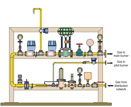
Figure 2.5.30. Typical valve train for gaseous fuel firing.
■ A self-operated shutoff valve that in the event of an over-pressure in the firing system would automatically cut off natural gas supply for the consumption point; should this valve close, it can only be reengaged manually by the firing system operator.
■ A self-operated, spring-adjustable, pressure-reducing valve that provides the final reduction of natural gas pressure to the value required by the firing system, usually between 0.5 and 2.0 bar.
At the natural gas supply pipeline to the main burner, which is an extension of the inlet pipeline but with a larger diameter, to accommodate gas expansion from its pressure reduction, the follow-ing control elements are necessary:
■ A metering set to read off the gas flow consumed by the main burner; the metering device is usually an orifice plate though sometimes a turbine-type meter is used.
■ A pressure gauge to measure the pressure upstream of the self-operated reducing valve.
■ Two tandem shutoff valves, remotely operated by the combustion control system. They are usually traditional solenoid valves or electropneumatic valves, or even electrohydraulic valves, and are characterized by their quick closing and slow opening.
■ A safety relief pipeline that starts at a take-off between two shutoff valves, and has a sole-noid valve that is normally open and releases gas discharge into the atmosphere when shut-off valves block the supply for the main burner.
■ A motor-driven or pneumatically driven control valve that opens or closes according to a larger or smaller demand for fuel by the firing system, thus modulating the natural gas flow.
■ A globe type or needle type manual valve for an eventual fine-tuning of the fuel flow to the firing system.
■ A pressure switch to monitor maximum pressure and to stop gas supply for the main burner should the upstream pressure of the valve train exceed a certain preestablished value.
■ A pressure gauge to show the pressure of the gas being supplied for the main burner.
At the natural gas supply pipeline for the pilot burner that starts at a take-off of the inlet pipeline, upstream to the pressure reducing valve would require a manual shutoff valve, and a shutoff valve, usually a traditional solenoid valve, remotely operated by the combustion control system.
• A natural gas firing system is extremely simple because the efficient firing of this type of fuel is less demanding if compared to the conditions that must be guaranteed to provide a good combustion with liquids and solids. There are basically two natural gas firing systems:
■ A low-pressure system, where the pressure of the natural gas that is supplied does not exceed 0.5 bar, and it requires primary air supply to guarantee good firing conditions.
■ A high-pressure system, where the pressure of the natural gas that is supplied remains between 1.5 bar and 2.0 bar. Sonic nozzles are used in this system and they introduce high turbulence to the fuel jet, which is why this system can sometimes operate without primary air supply.
Despite all the advantages and facilities associated with natural gas firing, there is a serious limiting factor for the use of this fuel by cement plants: the need of a gas distribution network close to the plant. The high cost per kilometer for building a gas pipeline of medium pressure makes it economically impossible to use natural gas by a cement plant if the implementation of a lengthy network to meet a specific consumer is necessary.
FINAL CONSIDERATIONS
In this chapter we tried to introduce a scenario showing the world availability of fuels and the characteristics inherent to the use of such fuels by cement plants during the first years in the 21st century. Nevertheless, this subject is too broad to be covered completely within the scope of this work. It is an extremely dynamic topic for cement plants. The factors such as socio-economic conditions and state-of-the-art combustion technology involved in the selection of a fuel or a fuel mix for a specific application are actually mutable and should be subject to continuous updating.
Because of the complexity of the problem of selection and use of fuels by the cement industry, the current chapter attempted, therefore, to present general data that can be referred to as an initial guideline for technicians working at cement plants, and mainly as an encouragement for studies and research on a quest for a specific solution that for each plant and at every particular instance will represent the best “triangular commitment” between costs, product quality, and interference with the environment
REFERENCES
Baukal, Jr., Charles, The John Zink Combustion Handbook.
Duda, Walter H., Cement data-book.