
Contents
Everything you need to know about Kiln Burning Systems
[wpecpp name=”package” price=”75″ align=”center”]
by Con G. Manias*
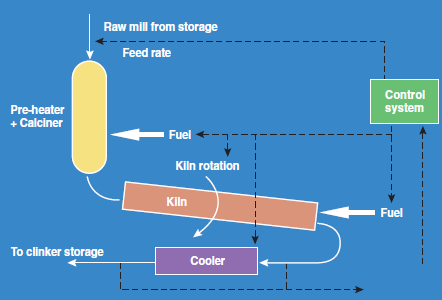
Once raw materials have been selected and blended, and ground and homogenized into a fine and uniform kiln feed, they must then be subjected to enough heat to allow the clinkering reactions to proceed. This is the pyroprocessing stage of cement manufacture, beginning with the kiln feed material extracted from storage and weighed and transported to the kiln, and finishing with the clinker from the cooler going to clinker storage. A schematic diagram on different stages of cement manufacturing is shown in Figure 3.1.1
The main chemical reactions to produce the calcium silicates that later give cement its bonding strength occur in the kiln system. There is a combination of endothermic and exothermic reactions occurring in an extremely complicated chemical reaction sequence. The raw material composition, mineralogical composition and the time and temperature profile of these materials in the kiln determine the ultimate composition and mineralogy of the clinker, which in turn determines the performance of the cement produced.
The pyroprocessing stage is generally regarded as the heart of the cement-making process. It is the stage in which most of the operating costs of cement manufacture appear, and is also therefore the stage where most of the opportunities for process improvement exist.
There are many different kiln system designs and enhancements, but they are all in essence performing the following material transformation, in order from the feed end:
1. Evaporating free water, at temperatures up to 100°C
2. Removal of adsorbed water in clay materials 100°C – 300°C
3. Removal of chemically bound water 450°C – 900°C
4. Calcination of carbonate materials 700°C – 850°C
5. Formation of C2S, aluminates and ferrites 800°C – 1250°C
6. Formation of liquid phase melt > 1250°C
7. Formation of C3S 1330°C – 1450°C
8. Cooling of clinker to solidify liquid phase 1300°C – 1240°C
9. Final clinker microstructure frozen in clinker <1200°C
10. Clinker cooled in cooler 1250°C – 100°C
Figure 3.1.2 shows the transformation reactions taking place at different stages of raw material pyroprocessing.
On the gas flow side, the sequence from the firing end is as follows:
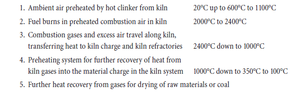
All kiln systems aspire to optimize heat exchange between the gas streams and material streams at various stages to minimize waste heat and maximize thermal efficiency.
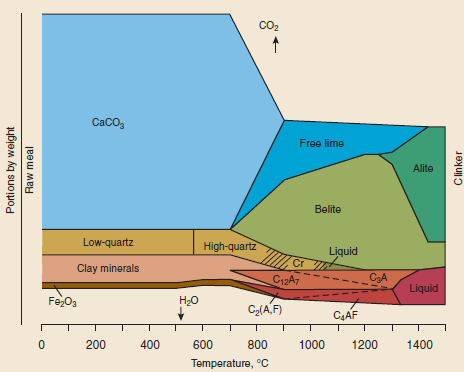
Figure 3.1.2. Clinker reactions in raw meal as a function of temperature.
KILN SYSTEMS
Early kiln systems for cement clinker manufacture were based on shaft kiln systems. However, as these are of little relevance to the world at large, this chapter will deal with rotary kilns only.
The first rotary kiln was introduced to the cement industry by Frederik Ransome (1885) when he took out a patent in England titled “Improvements in Manufacture of Cement.” The first of these rotary kilns were up to 2.0 m in diameter and 25 m long, with an “enormous” production of 30 to 50 ton/day. Today, some kilns are producing as much in a day (>10,000 tpd) as these kilns produced in a year.
Wet Process Kilns
The long wet process kiln, with a length to diameter ratio (L/D) of up to 40, was the main clinker producing plant for most of the 20th century. It is a relatively simple process, with the main advan-tage of slurry preparation being the eases of milling, handling, blending, storage, pumping, and metering. It is also less prone to low level dust emission.
In wet process systems, the material preheat system is metal chains hanging in the cold end of the kiln, which absorb heat from gases and heat the material which flows over them. The chain actually provides a greater surface area for contact between hot gases and the material clinging to the chains.
The main problem with long wet kilns is their poor fuel efficiency, because of the water to be evap-orated from the slurry. This became a severe problem only when the cost of fuel escalated during the 1970s, and only a few wet kilns have been built since that time. However, there are some rare situations where raw material moistures, cheap (waste) fuels, low technology workforce, or other factors may still favor wet process production.
Another disadvantage of a wet process kiln is that it is limited in production rate because of mechanical limitations on kiln size. A 1500 tpd wet kiln is a large kiln, with 2000 tpd being an upper economic limit without encountering severe maintenance prob-lems. Apart from the sheer weight and stresses on mechanical drives and supports, shell deflection makes it increasingly difficult to achieve acceptable refractory life. Figure 3.1.3 depicts a typical long wet process kiln.
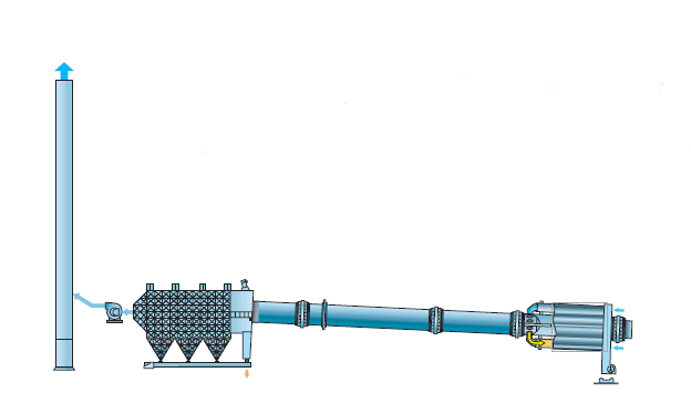
Figure 3.1.3. Long wet process kiln.
Long Dry Kilns
Dimensionally, long dry kilns are similar to long wet kilns. These kilns were developed and became popular particularly in North America. Their advantage over wet kilns is potentially improved fuel consumption because the kiln feed is dry. However, without any enhanced heat transfer fittings in the preheating zone, kiln exit temperatures of 700°C or more meant that water spray cooling was required, and very little advantage was realized over wet process. However, kiln internals fitted at a later stage of development included kiln chains (similar to wet kilns), kiln metallic crosses, and ceramic heat exchangers. The crosses and ceramic heat exchangers basically split the kiln into 3 or 4 cross-sectional areas over a distance of about 15 to 20 m, splitting both the feed and gas flow, and providing improved heat transfer.
With these enhancements, the kiln gas exit temperatures were reduced to 350°C – 400°C, specific fuel consumption improved some 30% and output increased by 35% to 40% compared to wet kilns.
Kiln production rates for long dry kilns are marginally higher than long wet kilns. A typical long dry kiln is shown in Figure 3.1.4.

Figure 3.1.4. Long dry kiln.
Travelling Grate Preheater Kilns (Lepol)
The Lepol kiln was invented in 1928 by Otto Lellep and marketed by Polysius, the combination of names leading to “Lepol.” This was a major improvement in kiln thermal efficiency, some 50% over the popular wet kiln process at the time, and led to ready market acceptance of the technology. The tech-nology reached the stage of 3000 tpd kilns with specific fuel consumption of 3.3 MJ/kg (800 kcal/kg).
These kilns have a short rotary kiln section, L/D of 12 to 15, preceded by a travelling grate covered by a 150 mm to 200 mm layer of nodulized raw meal. The kiln exit gases at 1000°C or so pass through this nodule layer providing preheat of material before it enters the rotary kiln at about 800°C. The gases exit the grate section at around 100°C, implying very efficient recovery of heat. For some grate preheater kiln systems, the kiln feed nodules experience two separate passes of the hot gases, the first for drying and the second for preheating and partial calcination. Figure 3.1.5 shows a typical Lepol kiln system.
The nodules or pellets formed as kiln feed can either be produced from dry raw meal mixed with about 13% moisture in a pan granulator, or produced from raw meal slurry after it has passed through a filter press and been extruded and sliced into cylindrical pellets.
The raw material properties are critical to the performance of the Lepol kiln system. The nodules or pellets formed have to be strong and plastic enough to withstand the mechanical handling and thermal shock on the grate without breaking down. Nodule breakdown causes blinding of the holes on the travelling preheater grate, increasing pressure drop, and reducing airflow and hence capacity of the kiln system.
The output of a particular kiln can vary by almost double depending on the suitability of raw feed for this process and nodule formation in particular.

Figure 3.1.5. Lepol kiln.
Cyclone Preheater Kilns
The cyclone preheater was first patented in 1934 in Czechoslovakia by an employee of F. L. Smidth. However, the first preheater kiln was built and commissioned in 1951 by KHD. This system utilizes cyclone separators as the means for promoting heat exchange between the hot kiln exit gases at 1000°C and the incoming dry raw meal feed.
Cyclone preheater kilns can have any number of stages between 1 and 6, with increasing fuel efficiency with more cyclone preheater stages as shown in Figure 3.1.6. The most common is the 4-stage suspension preheater, where gases typically leave the preheater system at around 350°C.
The rotary kiln is relatively short, with L/D typically 15. The material entering the rotary kiln section is already at around 800°C and partly calcined (20% to 30%) with some of the clinkering reactions already started.
Figure 3.1.6. Cyclone preheater kiln.
Material residence time in the preheater is in the order of 30 seconds and in the kiln about 30 minutes. Kiln speeds are typically 2 rpm. Preheater pressure drops range from 300 mm to 600 mm water, with gas duct velocities typically 20 m/s in the preheater and cyclones.
Kiln capacities up to 3500 tpd exist, with specific fuel consumption usually around 750 to 800 kcal/kg (3.2 to 3.5 MJ/kg). The larger capacity kilns are built with two preheater tower systems to keep cyclone sizes to economic proportions and required efficiency.
Cyclone Preheater Kilns with Riser Duct Firing
The operation of the cyclone preheater kilns can be improved by firing some fuel in the riser duct to increase the degree of calcination in the preheater. The production rate can also be increased marginally, depending on the limitation to output for a particular plant.
Preheater kilns can be subjected to flushing of material due to the fluidization of raw meal that occurs during calcination in the kiln. Increasing the degree of calcination in the riser (up to 50%) before the material enters the kiln reduces this tendency. Furthermore, burning some fuel in the riser duct reduces the fuel requirement and thermal loading in the kiln, thus improving the kiln refractory life.
In this kiln system, the excess air in the burning zone is increased, and the additional oxygen in the riser duct allows additional fuel to be burnt there. This can be an ideal place to burn some waste fuel such as waste oils or tires. The limitation as to how much fuel can be burnt in the riser can be limited by the geometry of the duct, combustion system design, or fuel type. However, even under ideal conditions, the fuel quantity is limited to about 25% of total fuel because of the limitation to the amount of excess air that can be passed through the burning zone. Too much excess air will reduce burning zone temperature to below the levels needed for clinkering. This reduction in burning zone temperature can be countered by oxygen enrichment, as discussed later in the paper.
Precalciner Kilns
In precalciner kilns, the combustion air for burning fuel in the preheater no longer passes through the kiln, but is taken from the cooler region by a special tertiary air duct to a specially designed com-bustion vessel in the preheater tower. Typically, 60% of the total fuel is burnt in the calciner, and the raw meal is over 90% calcined before it reaches the rotary kiln section. Since the calciner operates at temperatures around the calcination temperature of raw meal (800°C to 900°C), there may not be a flame as such. The calciner efficiency is dependent on uniform air flow and uniform dispersion of fuel and raw meal in the air. Typically, average residence times calculated on gas flow for early units were about 1 to 2 seconds for coal and oil, and 2 to 3 seconds for natural gas. In recent years, though, there has been a trend toward larger calciner vessels to reduce some of the combustion problems of the earlier designs and provide greater flexibility for using lower grade fuels.
Precalciner kilns can have very large outputs in excess of 10,000 tpd, with specific fuel consump-tion below 3 MJ/kg (700 kcal/kg). There are many different configurations, with one, two, or three preheater towers operating with one or two calciner vessels in either an in-line configuration or separate line configuration. Some (mostly recent) designs include a separate precombustion chamber. An in-line calciner has kiln exhaust gases and tertiary air making up the combustion air (reduced oxygen levels) for the calciner as shown in Figure 3.1.7, while the separate line system has tertiary air only with 21% oxygen forming the combustion air as is shown in Figure 3.1.8. A separate line system therefore has a better combustion environment and may be preferred for difficult fuels. It has a further advantage when converting preheater kilns to precalciners in that there is minimal inter-ference with the operating preheater kiln during the construction phase for the new separate line preheater tower and tertiary air duct.
Figure 3.1.7. In-line calciner system with single preheater tower.
Precalciner kiln systems can operate only in conjunction with grate coolers, as there is no provision for tertiary air off-take with plane-tary coolers.
L/D ratios are typically low at 10 to 14, and kiln speeds are in the order of 3.5 rpm. Kiln residence time is typically 20 to 25 minutes.

Figure 3.1.8. Separate line calciner system with two preheater towers.
Other Systems
The rotary kiln has been the standard clinkering unit for cement production over the past century. During that time, there have been various attempts to produce clinker in other reactors including a flash calcining/clinkering and fluid bed calcining/clinkering vessels The motivation has been to reduce capital and operating costs or to allow smaller economic clink-ering plants to be built in remote locations.
The author was involved with one such project during the 1980s, where clinker was produced in a fluid bed fed with raw meal. Although this did not proceed to commercialization, it was noted that the clinker produced from this pilot plant was much more reactive than any conventionally produced clinker, and gave cement strengths 20% higher than those produced from good quality rotary kiln clinker. This was thought to be due to the absence of overburning in the fluid bed clinker because of the more uniform temperature that can be achieved. The mineral structure certainly showed much finer alite and belite crystals in the 10 to 20 µm range. This gives some indication of the potential quality improvement possible through better control of rotary kiln temperature.
Critical data on the kiln systems discussed above are summarized in Table 3.1.1. The data reflects mechanical, operational, thermal, fuel, production, and efficiency parameters of each kiln system.
Table 3.1.1. Summary of Critical Data Information on Different Kiln Systems
VITAL KILN OPERATIONAL PARAMETERS
The following parameters are typical for any kiln operation and considered critical in optimizing the performance of a kiln.
Material Residence Time
The residence time of material in the kiln is governed by the kiln slope, the speed of rotation, and any internal restrictions either by design (dam rings) or through kiln ring formation.
The residence time, t, can be calculated from Equation 1:
t= residence time, min
L= kiln length, m
p= kiln slope, degrees
D= kiln diameter, m
n= kiln speed, rpm
![]()
![]()
= angle of repose of material, (40 degrees)
F= constriction factor (usually1 if no dams, lifters etc.)
Kiln Degree of Fill
This is the percentage of the kiln cross-sectional area filled by the kiln charge, and is usually in the range of 5% to 17% for most rotary kilns. It should be noted, though, that a fill degree of more than 13% could impair heat transfer in that some of the material in the center of the charge will not be exposed to enough heat. It is sometimes seen that a kiln ring could coincide with high or erratic free lime in the clinker, possibly because the fill degree has exceeded limits for ensuring that all kiln charge material is uniformly heated.
Kiln Slope
Rotary kilns slope from the feed end to the discharge end for material to travel in that direction utilizing gravitational force. The slope is typically 2% to 4%, or 1 to 2°, and is decided in conjunc-tion with the kiln rotational speed. A lesser slope with a higher rotational speed may improve heat transfer because of the greater tumbling of kiln charge.
Kiln Capacity
When designing a kiln for a certain capacity, or when evaluating an existing kiln for potential output, there are a number of key parameters that must be evaluated. These include:
• Burning zone heat loading
• Secondary air velocity
• Burning zone gas velocity
• Kiln exit gas velocity
• Kiln exit gas temperature
• Preheater tower gas velocities
• Preheater tower pressure drops
• Preheater tower exit gas temperature
• Volatile concentrations
• Material residence time
• Cooler grate loading
• Cooler air supply
• Kiln dust cycles
There are design limits for all of the above that may vary between different processes, but any of the above could be the limitation to a kiln’s output. These limitations will typically manifest them-selves as kiln instability and ring or coating buildup,excessive dust loss, poor refractory life, poor clinker quality, or high fuel consumption. Usually, however, the limitation is found to be more a question of a fan capacity, a burner capacity, or milling of raw materials or coal.
CLINKER COOLERS
Cooling of clinker takes place at two locations: 1) in the kiln after the material passes the burning zone region, and 2) in the specially designed clinker coolers after the material falls out of the kiln.
The rate of cooling can be critical to the clinker quality and performance of cement. The rate of cooling in the kiln is determined by the flame and resulting heat flux, flame temperature, and speed of material flow through the kiln. As the clinker temperature exiting the kiln is normally 1200°C to 1250°C, the clinker characteristics have been already largely established before the clinker enters the cooler. A long flame gives slow heat-up and slow cooling of the kiln charge before it falls from the kiln. This will tend to produce clinker with large alite and belite crystals, resulting in a coarse-grained clinker matrix with poor reactivity and poor grindability. Slow cool-ing can also result in reversion of C2S from the α’ phase to the less reactive β form, or in extreme cases even to the unreactive γ form, and can even allow C3S to revert to C2S and CaO. All of these have a negative impact on cement strength.
A further quality problem can arise if there are high levels of MgO in the clinker, because slow cooling allows large periclase crystals to form such that when these hydrate slowly in concrete, the expansion can cause the concrete to rupture.
There are two main types of coolers used in cement clinker production. These are the satellite (or planetary) type and the oscillating grate type. The 1990s saw tremendous advances in clinker cooler technology that greatly improved heat efficiency and potential output from a given kiln system.
Clinker coolers perform the function of:
• Transporting clinker from the kiln to the clinker delivery system
• Cooling the clinker to a safe temperature for subsequent transport
• Finalizing the clinker mineralogy through rapid cooling
• Preheating combustion air by heat exchange with hot clinker
Coolers are treated in more detail elsewhere in this publication and will not be elaborated on further here.
KILN BURNERS
Combustion and the Cement Process
Pyro-processing is the heart of the cement-making process. It is usually the major cost element and kiln performance dictates the efficiency, plant output, emissions, product quality, and plant run factors. Combustion will be the major factor in determining kiln performance, and seemingly small improvements here can have a major impact on the economics of running the whole plant. An additional 5% to 10% production in a year will impact spectacularly on the profit line given the large proportion of fixed costs at a cement plant.
The cement kiln requires a particular heat transfer regime for best fuel economy, optimum prod-uct quality and maximum production. Generally, a short hot burning zone at the front of the kiln is optimal. This gives rapid heat up and cool down of clinker to give the best reactivity, reduced back end temperature for minimizing heat losses in the exit gases and from shell radiation, best use of I.D. fan capacity, and reduced NOx formation. This needs to be balanced against refractory heat load and kiln operating stability. The flame must not impact on the kiln charge or refractories and complete combustion must occur in the kiln to reduce potential for build up and ring formation.
When deciding on a burner, it can be false economy to simply select on the basis of initial purchase price alone, and suffer long-term poor performance for the plant or extended commissioning times. The capital investment in a cement plant is substantial and it is high risk to entrust the performance of this investment to a relatively low-cost component (the burner system) without taking all reasonable steps to mitigate this risk.
Sadly though, it is often the case that evaluation and choice of burners either for new kilns or replacement systems is based on capacity and purchase price only, without much indication of how they will perform with the specific kiln under consideration.
The combustion system should be considered as an integral part of the pyro-processing system, including kiln, cooler, tertiary air ducts, calciner etc., and be designed with due consideration of this total system.
Kiln Aerodynamics
It is surprising how small differences in cooler throat, cooler bull nose, kiln hood, tertiary air off-takes, secondary air temperature and velocity, and air leakage points to name a few can have an enormous effect on the air flow patterns in the combustion environment of the rotary kiln.
Tertiary air inlet design and location, and tertiary air temperature and velocity will likewise deter-mine the airflow patterns in a flash calciner.
The fuel introduced by the burner will clearly be influenced by the secondary and tertiary air flow patterns, given that 85% to 100% of the combustion air comes from this source and the momen-tum of these large airflows dominates the combustion region. Typical aerodynamic patterns in two different kiln combustion zones are shown in Figure 3.1.9-a,b.
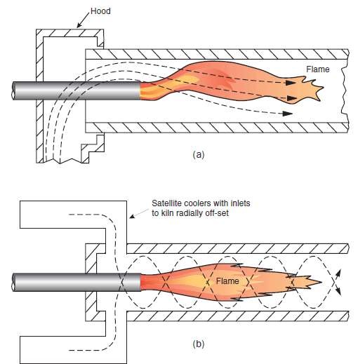
Figure 3.1.9-a,b. Some typical kiln aerodynamic patterns encountered during kiln studies.
Total System Considerations in Design
In order to ensure that all relevant factors are taken into account in combustion system design, process parameters and kiln system design must be considered when designing a burner for a given application.
In particular, modeling techniques can be used to analyze the fuel/air interaction in combustion environments and for predicting heat release and heat flux profiles. Such modeling takes into consideration specific parameters including:
• Geometric design of cooler, cooler bull nose, cooler throat, kiln, off-take ducts, burner posi-tion, burner angle, burner channels (types, numbers and sizes), calciner size and shape, and tertiary air inlet
• Process design, such as fuel rate, type, properties; primary air mass and velocity; secondary air and tertiary air temperature, mass and velocity; production rates; heat transfer (convection, conduction, radiation); and heat flux profiles developed
As no single modeling technique can provide all the answers, a combination of physical and math-ematical modeling provides the best information for arriving at an optimized burner design. Observation from a fuel/air mixing model using acid-alkali techniques is shown in Figure 3.1.10. The overriding consideration when implementing results of modeling work is understanding the limitations and the conclusions that can be drawn from each technique, as well as ensuring that the techniques used have been adequately validated.
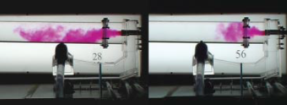
Figure 3.1.10. Fuel/Air mixing modeled using acid-alkali techniques.
KILN BURNER TYPES
The following section will cover the types and operational features of different burners used in cement manufacturing.
Turbulent Jet Diffusion Burners
For most kiln burners, fuel/air mixing occurs as a result of secondary air entrainment into the fuel and primary air jet. Friction between the different jet streams creates local turbulence at the boundaries with the fuel jet expanding as it entrains surrounding air. The nature and rate of mixing is determined by the relative momentum of the various jet streams as well as the system aerodynamics.
In a rotary kiln, the secondary air to be entrained into the fuel jet is limited to that coming from the cooler, and the expansion of the fuel jet is constrained by the diameter of the kiln. If the burner jet momentum (fuel and primary air) is less than that required for complete entrainment, then fuel/air mixing will be inadequate for good combustion, and a long, lazy flame with high CO is the likely result.
If the burner momentum is greater than that required for complete secondary air entrainment, then the excess momentum of the fuel jet is dissipated in pulling back exhaust gases from further down the kiln into the flame. This so-called “recirculation” has a positive effect in stabilizing the flame (making it less susceptible to minor process fluctuations) and in protecting refractory surfaces from burning fuel particles. Note though, that too much recirculation can be detrimental to fuel efficiency and produce an overly aggressive combustion environment. An ideal flame from use of secondary air entrainment and recirculation is shown in Figure 3.1.11.
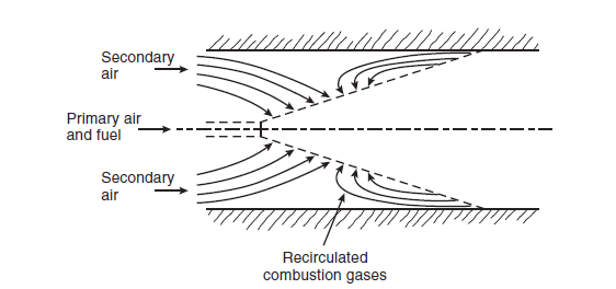
Figure 3.1.11. Idealized flame in rotary kiln showing secondary air entrainment and recircula-tion of combustion gases indicating adequate burner momentum for satisfactory fuel/air mixing.
Good burner design therefore requires optimizing fuel jet momentum and primary air mass and velocity to create a recirculatory flame while interacting with that particular kiln system’s aerodynamics. The secondary air temperature, mass, velocity, and directional flows must all be considered in the design process as these affect the burner system design. The variables to optimize include primary air mass and velocity, axial and radial flow splits, fuel jet momentum, and burner insertion length and direction. A typical multi-fuel burner used in a rotary kiln is shown in Figure 3.1.12.

Figure 3.1.12. Typical multi-fuel burner.
Excess Air Levels
One symptom of combustion problems is the need to oper-ate with abnormally high excess air levels to avoid high CO at the kiln inlet. While 5% to 10% excess air is normal to achieve good combustion, levels above this represent a severe economic loss to the plant. This loss manifests as high specific fuel consumption (losses in exhaust gases), and high specific energy consumption (greater volume of exhaust gases), as well as lost output for a given kiln (normally fan or draft limited). Figure 3.1.13 shows a relationship between excess air and fuel efficiency during the kiln operation.
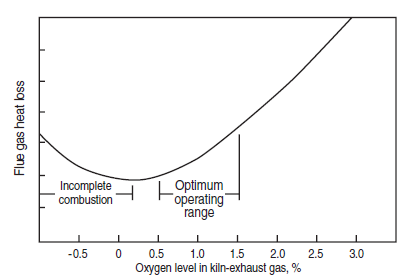
Figure 3.1.13. The effect of excess air on heat loss and fuel efficiency.
Flame Stability
Unstable flames adversely affect kiln operation as well as being unsafe to plant and personnel. An unstable flame is one that has a varying ignition point and a variable stand off distance from the burner tip as shown in Figure 3.1.14. There is a high risk of flame out, and substantial amount of unburnt fuel between the burner tip and the ignition point that is a potential explosion risk. Gas burners are more prone to instability because of the high ignition temperature, slow flame propa-gation speed, and narrow flammability limits for this fuel.
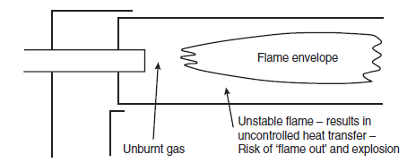
Figure 3.1.14. Unstable flame due to variable point of ignition.
Ensuring early ignition of fuel entering the combustion zone enhances flame stability. In some applications, this can be by a continuous pilot burner, but in rotary kilns this is best achieved by ensuring recirculation of hot gases as the ignition source for new fuel. Once a kiln is up to operat-ing temperature, radiation from refractory provides the ignition energy.
External circulation from properly designed burners brings hot combustion gases back into the com-bustion region to help stabilize the ignition point. Internal circulation can be even more effective.
Internal circulation can be induced by the use of a bluff body to create a low pressure region in the center of the burner nozzle that then draws hot combustion gases back into this region. This can then act as the ignition source for the new fuel. Bluff bodies, though, can suffer heat damage in this demanding location (see Figure 3.1.15).
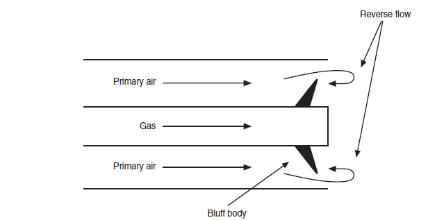
Figure 3.1.15. Stabilization of flame with internal recirculation created by bluff body.
A more durable means of creating internal flame re-circulation is the use of swirl in either the fuel or primary air jet stream as shown in Figure 3.1.16. However, swirl would broaden the flame that can adversely affect refractory life due to flame impingement (see Figure 3.1.17). In gas firing, the most effective design uses limited swirl for both primary air and gas fuel. In oil firing, primary air swirl is typically used, while for solid fuel firing swirl is often unnecessary for producing a stable flame. Each case is designed on the merits of the fuel and the combustion environment in which it will operate.
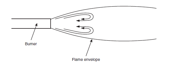
Figure 3.1.16. Flame stabilized by internal circulation.
Figure 3.1.17. Flame impingement on refractory in the absence of re-circulation.
Gyro-Therm Burners
The Gyro-Therm® “Precessing Jet” burner technology has been designed to be mechanically very simple, but the novel fluid-mechanical flow provides a genuinely new way of mixing fuel and air. This produces flames with different characteristics (compared to turbulent diffusion jet burners) that have been proven to give operational and environmental advantages in kiln firing.
This emerging technology has so far been used in gas burning or gas/coal burning applications. However, a coal-only burner using Gyro-Therm technology is near commercialization.
The precessing jet nozzle used in these burners produces a fuel jet stream exiting the burner nozzle that exhibits a stirring action into the combustion environment as shown in Figure 3.1.18.
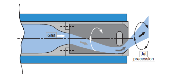
Figure 3.1.18. Cross sectional diagram of the precessing jet nozzle and the flow field generated from it.
The flame itself does not precess. The effect is to produce large-scale mixing, via the “stirring” action of the jet and a rapidly spreading flame. This is in contrast to the fine scale mixing of turbu-lent jet diffusion burners. The precessing motion is generated without any moving parts within the Gyro-Therm nozzle.
The resultant effects of this new technology include:
• Sub-stoichiometric combustion within flame envelope with complete combustion at the flame boundaries in a normal kiln environment
• Highly luminous flames enhancing heat transfer to kiln charge
• Low axial velocity of fuel jet giving short bulbous flame
• Low thermal NOx formation
• No primary air needed for gas fuel and a stable flame anchored to the nozzle
Although the flame spreads more than that from a conventional turbulent jet nozzle, the amount of spread can be controlled. This fact is important in rotary kilns where direct impingement of a flame on the product could produce instability or reducing conditions which would be detrimental to product quality or damage the refractory. A simple but extremely effective flame shaping tech-nique is built into the burner. The technique for flame shape adjustment is based on a high momentum gas jet injected at a critical point into the precessing jet flow field. This jet (termed the center body jet, CBJ) is expelled through the center body of the precessing jet nozzle, modifying the pressure fields within the vicinity of the burner in such a way that the fuel gas is directed more toward the kiln axis. As the proportion of gas is increased through the center body jet, the flame spread is reduced and the heat flux profile lengthened. An air channel is provided for burner cool-ing and for flame shaping during the warm-up phase. A schematic of Gyro-Therm burner with gas channel for flame adjustment and cooling air is shown in Figure 3.1.19.

Figure 3.1.19. The design of the Gyro-Therm burner includes an additional gas channel for flame shape adjustment and optional cooling air.
CALCINER BURNERS
Calciner combustion is quite different from kiln combustion. Often, there is no defined flame in the vessel, with oxidation of the fuel occurring under “flameless” conditions. As for any combus-tion environment, satisfactory fuel/air mixing is the first requirement for good combustion. Calciner aerodynamics are dominated by the tertiary air due to its mass and comparatively high velocity at the calciner inlet. The airflow patterns can become quite complex with changes in the calciner cross section producing effects such as strong recirculation zones and streaming as depicted in Figure 3.1.20.
With such prevailing conditions, the location and design of cal-ciner burners can become extremely critical to the per-formance of the calciner. As for kiln burners, physical modeling can reveal the flow patterns within a calciner, and allow the location of burners and their design (injection velocities and momentum) to be determined for best performance. Furthmerore, modeling can often determine simple redesign of internal refractory profiles to produce much improved calciner aerodynamics and hence greatly improve calciner combustion.
Due to the short residence time in calciners (2 to 3 seconds), combustion can be sensitive to fuel properties. Some fuels such as petcoke – because of its low volatile content, and natural gas –because of its more stringent combustion prerequisites, require more residence time (larger calciner) for satisfactory combustion.
Calciner burner designs can vary from a simple pipe through which to introduce fuel, to more sophisticated designs that are smaller versions of kiln burners. In most cases, a simple pipe will perform as well as the more complex designs if it is correctly located and designed. This is obvi-ously a cheaper capital and operating cost solution. Only in rare cases will primary air be required in a calciner burner to overcome any serious aerodynamic problems.
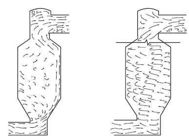
Figure 3.1.20. Typical aerodynamic problems encountered in calciner operation that impair calciner combustion.
OXYGEN INJECTION
The technical benefits available from using oxygen to replace air for combustion in cement kilns have long been recognized. These benefits arise from increased flame temperature (leading to improved heat transfer rates), faster reaction rates with some difficult fuels, and reduced combus-tion gas volume (due to less nitrogen).
In general, this will lead to reduced specific fuel consumption (less waste gas volume and better heat transfer) and increased production from a particular kiln. The effect on NOx emissions will be variable, but with small amounts of oxygen substitution NOx will usually increase as a conse-quence of elevated flame temperature.
However, the cost of oxygen has generally been prohibitive in the past, preventing the wholesale use of oxygen to enhance cement kiln performance.
The availability of cheaper production methods for oxygen such as the vacuum swing adsorption process, together with increased demand for cement,have combined in some regions to make the strategic use of oxygen a viable alternative for increasing production. This is particularly so where short term peaks in demand are encountered and oxygen injection can be implemented without significant plant down time for modifications.
Oxygen injection can be carried out either in the kiln or calciner. A process evaluation of the specific kiln system will reveal the most advantageous point. Generally, this will involve identifying bottlenecks to increased production and how these can be addressed through the use of oxygen. A modeling strategy for designing oxygen-injecting system for a calciner is shown in Figure 3.1.21. Strategic use of oxygen can impart the following processing benefits:
• Allow more fuel to be burned in either the kiln or calciner where fan capacity is limiting output, and therefore increase output
• Reduce gas velocity in the burning zone, kiln back end, calciner exit, through the preheater tower, or through the bag filter or electrostatic precipitator
• Reduce pressure drop through the kiln system because of reduced gas velocities
• Reduce preheater exit temperature because of higher feed-to-gas ratio
• Increase calciner residence time
Increase flame temperature and heat transfer to material
Figure 3.1.21. Modeling to determine the design of the oxygen injection system into the calciner.
However, there are also potential risks of overheating refractories and kiln charge or calciner feed unless due consideration is given to the design of injection points and oxygen lances.
KILN THERMAL CONSIDERATIONS
The function of the kiln system is to convert the raw meal into clinker in the most efficient way and to produce clinker with an optimal mineralogy for acceptable cement performance.
Typical chemical analysis of raw meal, clinker, and select processing parameters are given in Table 3.1.2.
Table 3.1.2. Typical Composition of Raw Meal, Clinker, and Relevant Processing Parameters
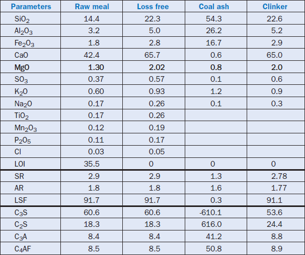
The hypothetical compounds are calculated using the Bogue equations to determine the percent-age of calcium silicates (C3S and C2S), calcium aluminate (C3A) and calcium alumino ferrite (C4AF) phases, which would be present in the clinker if all reactions proceeded to completion under equilibrium conditions. In reality, the calculated or hypothetical composition differs from actual analysis of clinker by X-ray diffraction or microscopic analysis. This is because chemical equilibrium is reached only occasionally, and the degree to which actual analysis differs from the calculated analysis is influenced by the heat treatment of the material. In addition, small amounts of trace elements can have a profound effect on the eventual mineralogical composition of clinker.
In general, it is found that:
• Alite content is usually higher than the calculated amount by an average of 13%
• Belite is usually lower than the calculated amount by an average of 6%
• Aluminate and ferrite phases can be either higher or lower, but on average are 2% lower than calculated
The critical stages for clinker quality are:
• The heat-up rate of the kiln charge after the calcination process
• The maximum temperature and residence time at that temperature
• The cooling rate to below 1200°C
These stages determine the size of alite and belite crystals and their reactivity, the formation of these crystals (α, β, γ), and the nature of the liquid phase, as well as the position in the structure where minor elements such as Mg, Na, and K, are found; all are critical to cement quality.
Some aspects of plant operation that help kiln performance are kiln feed size, homogeneity, kiln time/temperature profile, heat balance, and volatile and dust cycles; these are discussed in the following sections.
Kiln Feed Sizing
The kiln feed must be ground finely enough, within the context of the raw materials mineralogy, to allow the particles to react together within the time and temperature conditions in the kiln. Coarser particles require a higher reaction temperature and are likely to form relicts of the larger particles they originate from as alite and belite clusters.
Kiln Feed Homogeneity
Localized chemical variations that occur when kiln feed is not properly homogenized mean there are different localized requirements for raw meal to form clinker.In a kiln situation, this will imply that some of the easier-to-burn regions may be overburnt in order to completely burn the diffi-cult-to-burn regions. The difference between well homogenized and poorly homogenized kiln feed can be an increase of up to 200°C in the operating temperature of the burning zone, the associated high fuel consumption, high NOx, poor refractory life, and poor product reactivity.
Localized variations can also be created by deposition of coal ash on the kiln charge or irregular return of kiln dust back to the kiln.
Time/Temperature Profile
The kiln charge must spend sufficient time at a high enough temperature to reach near complete reaction to form clinker minerals. There must be no material flushing or underburning, as this produces poor quality clinker. The material bed must tumble adequately to ensure uniform heat-ing through the mass.
If clinker is underburnt, it will form small crystals of alite surrounded by abundant (solidified) liquid phase, whereas the belite will exist in discrete clusters. There may also be significant free lime present together with alite and belite, which has not had the opportunity to completely react. Overburnt clinker will have large alite and belite crystals, and exhibit poor reactivity.
Kiln Heat Balance
A summary of a typical kiln heat balance during clinkering reaction is shown in Table 3.1.3.
Table 3.1.3. Summarized Data on a Typical Kiln Heat Balance

Add Inefficiencies

The heat of formation (Q) of the clinker minerals is a function of the chemical composition and the mineralogical composition. It can be expressed as kcal/kg in a general equation as follows:
![]()
![]()
Where hH = % water of crystallization in the clay, g/100g clinker, and all analyses are on clinker.
If alkalies are present, the heat of formation is reduced by about 2 kcal/kg.
Kiln Volatile and Dust Cycles
The kiln burner is the main source of heat input to the rotary kiln and is primarily responsible for setting the heat flux profile in the kiln. However, there are other significant but insidious factors which need to be considered.
Firstly, there are dust cycles in the system which move heat around, such as:
• Dust cycle between the cooler and kiln, where 5% to 10% of the clinker is recycling between the two, moving high grade heat from the kiln to the cooler, and returning back to the kiln at lower temperature.
• Dust cycle between the burning zone and the back of the kiln, removing heat from the burn-ing zone to the back of the kiln. This can be about 10% of the kiln throughput.
• Dust cycle between the kiln and the preheater kiln, taking some 10% of kiln feed and associ-ated heat back into the preheater.
• Dust cycles between cyclone stages, where 20% to 30% of material flow is returned back to higher cyclones.
• Kiln dust losses, amounting to some 10% of kiln feed, which are lost to the kiln system.
These dust cycles can limit a given kiln’s output, as increasing gas velocities through the system will eventually render the kiln inoperative. The increasing dust loads will increase kiln back end temperatures and reduce kiln burning zone temperatures, leading to kiln instability.
Secondly, there are phase changes that move heat within and around the system in the form of latent heat of the materials. This includes:
• Volatile materials which vaporize in the burning zone (predominantly alkali sulfates, and chlorides) and recondense in cooler parts of the system, releasing the latent heat
• Liquid phase materials which melt in the hotter parts of the kiln and resolidify in the cooling section of the kiln
• Some phase changes occurring in the main clinker minerals as they cool
Other less insidious factors are the sensible heat of introduced streams, the secondary air heat input to the kiln, the calcination reaction, and heats of formation of the various components.
The heat exchange occurring within a kiln is therefore a multi-dimensional phenomenon.
KILN RINGS AND BUILDUPS
The formation of kiln rings and subsequent buildups result from melt formation followed by solidification that act as binder for dust particles to agglomerate. There are also other factors that lead to different mechanisms and types of ring formation as are discussed in the following sections.
Kiln Volatiles
The kiln volatiles referred to in cement manufacture are those compounds that volatilize in the burning zone of a rotary kiln and recondense in the cooler parts of the kiln or preheater. They are usually sodium or potassium sulfates and chlorides, but can also include certain calcium salts. Their melting points and relative volatilities in the kiln burning zone are given in Table 3.1.4.
Table 3.1.4. Melting Points and Relative Volatilities of Different Compounds in Kiln Burning Zone

These materials are not usually in the pure form, but form a eutectic mixture with an overall melt-ing point below that of the pure salts. In practice, these salts generally will appear in the melt in the temperature range of 600°C to 800°C.
The volatile compounds cannot readily escape from the kiln system because they condense (before they can be removed in the exit gas stream) and re-enter the kiln. Their concentration will therefore continue to build, sometimes reaching a concentration in the recycle stream significantly greater than the concentration in the raw materials. As they pass through a sticky condition during the melting/vaporization and recondensing stages, they can be catalysts for forming coating buildup in the preheater tower and rings in the back end of the kiln. These can be particularly disruptive to kiln operation in the cyclone preheater tower, and older preheater kilns can run into severe opera-tional problems because the effect of the volatile cycle was unrecognized in their design.
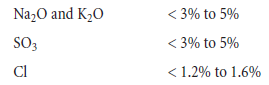
As a guide, the acceptable concentration limits of these materials (as % of clinker) in the kiln riser are:
The factors that influence the volatility of these materials are:
• The gas velocity in the burning zone has a strong influence on the volatility of these materials. A higher gas velocity reduces the vapor pressure of volatiles in the atmosphere, increasing their volatility. A kiln operating beyond its design limitations could be adversely affected.
• A higher burning zone temperature as required for harder burning mix will increase volatility.
• A higher CO2 concentration in the kiln will increase volatility of sodium and potassium.
•Reducing conditions will increase the volatility of sulfur, while higher oxygen levels will decrease it. The equilibrium reaction is
![]()
![]()
A low oxygen level shifts the equilibrium to the right. The volatility of sodium and potassium is less affected by oxygen levels than that of sulfur.
• Increased water vapor promotes formation of alkali hydroxides that are more volatile than the sulfates. Potassium volatility is increased at 1200°C, while sodium volatility is increased at 1400°C.
• SO(from the fuel) reduces the volatility of potassium, while the sodium volatility is unaffected.
• The mineralogical composition of raw materials producing volatiles is a major determinant of the alkali volatility, depending on the alkali carriers. Mica > illite > feldspar. Also, an easier burning material means lower burning zone temperature and hence less volatility.
• The fineness of raw meal has an indirect effect if it produces an easier burning mix.
A further factor is the alkali-to-sulfur ratio. Alkalies will preferentially combine with any chloride present. The best alkali-to-sulfur ratio is when there is just enough sulfur present to combine stoi-chiometrically with the remaining alkalies. If there is an excess of sulfur, then calcium sulfate will form from which the sulfur will volatilize completely.
If there is an excess of alkalies, alkali aluminate can form which will cause stiffening problems in concrete and mortar. There are also likely to be rings and buildup formed in the kiln system from a variety of other alkali salts produced.
In some cases, where low alkali cement is the target, and there is an alkali bypass installed. Alkali volatility is an advantage, and CaCl2 can be added to the mix to promote alkali volatility.
Preheater Kiln Middle Rings
These are dense hard rings that form at 7 to 10 kiln diameters from the kiln discharge and are typi-cally 15 to 20 m long. They are clinker-like in appearance and composition.
The mechanism of bonding is freezing of the clinker phase when clinker dust is carried from the burning zone and deposited on a cooler refractory surface (< 1250°C) behind the burning zone. The liquid phase freezes and binds the clinker particles together. The kiln charge material is still too fine to break up the formation at that point, and it will continue to grow.
This type of buildup is the result of a long cool flame in the kiln, together with high burning zone gas velocities laden with dust.
Sinter Rings
Sinter rings form at the beginning of the burning zone, and they also have an appearance and composition like clinker. These rings establish at the point in the kiln where the liquid phase is beginning to form, but during the course of a kiln turn, the melt comes into contact with a cooler surface and resolidifies, binding clinker particles together. This process can repeat until a ring forms. This type of ring is most likely to develop where there is a long and flat heat flux profile in the kiln.
Coal Ash Sinter Rings
These rings tend to develop when high ash coal is used at a position 7 to 8.5 kiln diameters from the discharge end. The rings are usually dense, often layered, sometimes glassy, and have a compo-sition and mineralogy similar to clinker.
The rings form when sticky ash impinges and deposits onto the refractory surface. As the kiln turns, some of the kiln charge material adheres onto the sticky ash. The ring gradually builds as more and more ash and charge material stick on top of each other as the kiln operates.
Clinker Rings/Cooler Inlet Deposits
These types of rings form at the kiln discharge end or as buildup in the cooler inlet. Such a ring is due to the liquid phase solidifying and binding clinker pieces together. It is usually a symptom of slow cooling in the kiln.
Kiln Charge Balls
These can form upstream of sinter rings, and can be up to 1 m in diameter. They are made up of a combination of calcined material generated by stripping and balling up of old coating, agglomera-tion of clinker and salt melt, or a ring acting as a dam and retaining material for a long time. Chemically, they are usually made up of a relatively low melting point eutectic mixture.
Minimization of Kiln Buildup and Rings
Kiln rings can be minimized by:
• Stable kiln operation, such as uniform feed rate,chemical composition, and fineness of coal and raw meal, and a well-designed combustion system
• Lower kiln system velocities and dust loads
• Lower volatile cycles attained by:
– choice of raw materials
– minimize < 20µ material in raw meal
– discard some kiln dust to control % volatiles in kiln
– eliminate cold air leakage into the P/H to avoid cold spots
• Avoid sinter rings by controlling liquid phase level and selecting refractories less prone to clinging by liquid phase
• Avoid coal ash rings by using lower ash coal or improving burner design
• Avoid clinker rings by burning closer to the kiln discharge (burner design) and using blasters for any snowmen in cooler
• Maintain an oxidizing environment in the burning zone
• Maintain a short heat flux profile (burner design)
• Optimize chemistry and mineralogy of raw mix to give an easier burning kiln feed
• Optimize kiln aerodynamics to avoid high velocity areas and flame impingement
CONCLUSIONS
The heat transfer processes occurring inside a kiln are multi-dimensional and extremely compli-cated. There is no single factor that can be considered in isolation when seeking to optimize kiln performance and product quality.
The raw materials and kiln feed preparation will have a major impact on kiln performance and will set the blueprint for fuel economy, kiln stability, clinker quality, refractory life, kiln throughput, and environmental impact. The kiln operation and the combustion system will determine as to what extent the potential inherent in the raw materials will be realized.
An optimization approach to a cement manufacturing plant should therefore consider a total holistic approach from the quarry to the lorry, examining each stage in detail and the impact of each stage on the total plant operation and economics.
REFERENCES
Ransome, F., Improvement in Manufacture of Cement, English Patent #5442, May 2, 1885.