Quick answer
If an ESP field current drops after a rapping sequence, compare the electrical trace immediately before, during and after the rap rather than treating the low current as a generic gas-flow fault. A brief change can be normal as the dust layer is disturbed, but a persistent low-current condition can indicate discharge-electrode fouling, excessive sparking, electrode misalignment, a grounded/broken component, high-resistivity dust or a T/R-control limitation. Correlate secondary voltage/current, spark rate, rapper identity and timing, opacity/emissions trend, hopper condition and neighboring-field behavior before changing rapper intensity or electrical limits.
Problem / job
ESP Field Current Low After Rapping Sequence is occurring repeatedly or outside the expected operating pattern and requires a cause-based diagnosis rather than trial-and-error adjustment.
Evidence
Capture secondary voltage/current, spark rate, rapper identity and timestamp, rapper intensity/frequency, opacity or particulate trend, hopper level/discharge condition, gas temperature and the behavior of adjacent ESP fields on the same time base.
Decision
Separate a short-lived rapping transient from persistent electrical limitation. If only one field stays weak, focus on its electrodes, insulators, rappers and T/R controls; if several fields move together, investigate dust resistivity, gas condition or shared process changes.
As-found evidence capture
Before intervention, trend the affected T/R set through at least one complete rapper event. Record secondary voltage, secondary current, spark rate, rapper identification and timestamp, rapper intensity/frequency setting, hopper level/discharge status, gas temperature and process load. Place the adjacent ESP fields on the same time base so you can see whether the event is local to one field or follows a plant-wide dust/resistivity change.
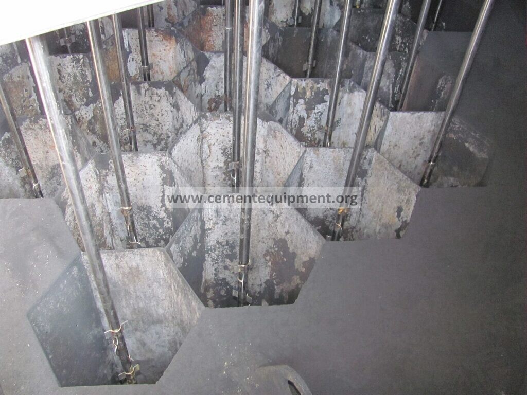
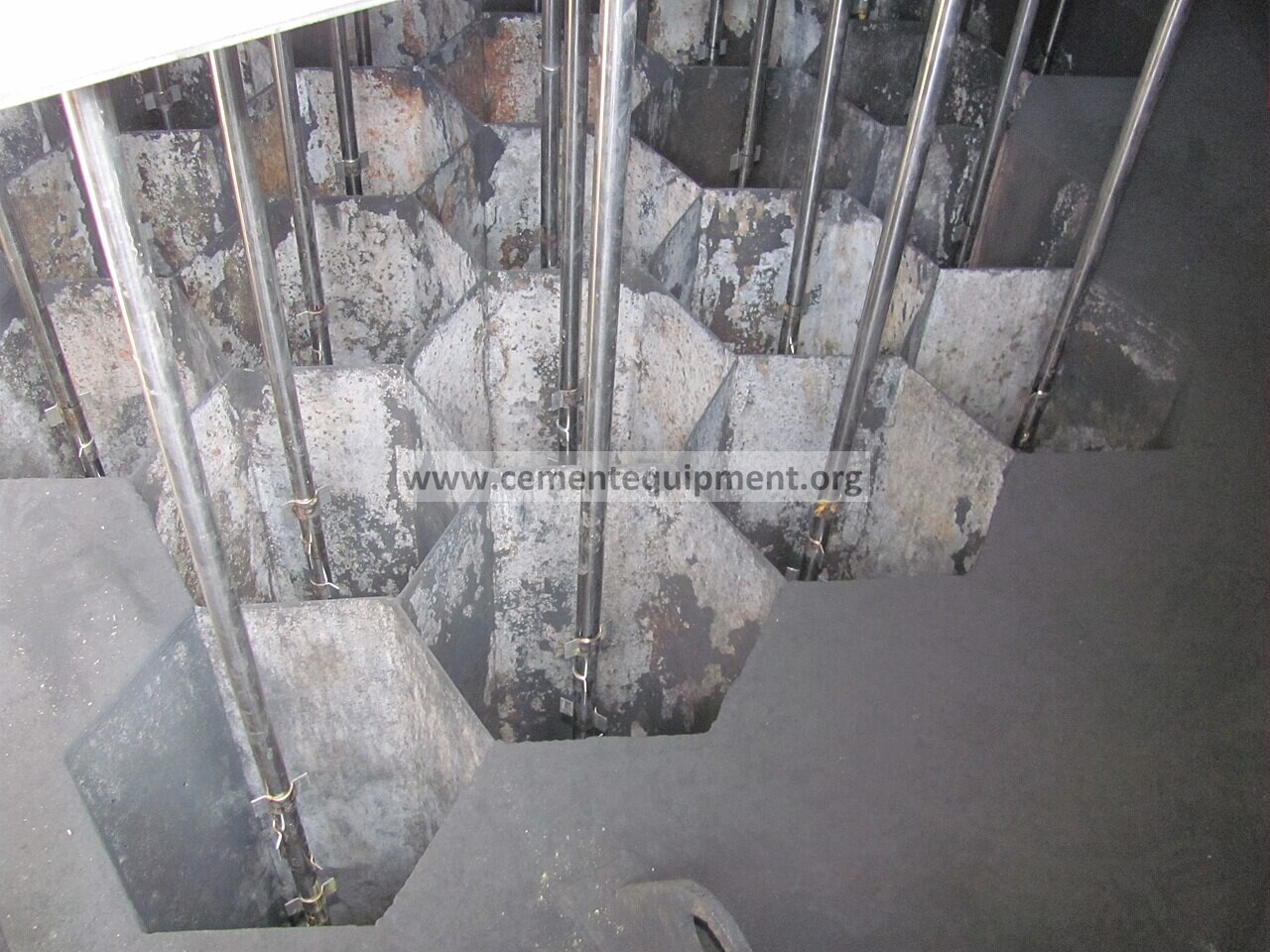
At the next safe inspection, document collecting-plate and discharge-electrode dust buildup, electrode alignment, insulator cleanliness/heating, rapper mechanical condition, broken or grounded electrodes, hopper dust accumulation and any arc/tracking evidence. Preserve the electrical trend before cleaning: the before/after pattern is part of the diagnosis.
Field checklist before changing rapper or T/R settings
- Trend secondary voltage, secondary current and spark rate through the complete rapper event.
- Identify exactly which rapper or rapper group operated when the current changed.
- Compare the affected field with adjacent fields under the same gas condition.
- Check hopper level and dust discharge so falling dust is not backing up into the electrical section.
- Confirm insulator heating/cleanliness and look for evidence of moisture or tracking at the next safe inspection.
- Review whether the low current is temporary or persists after the normal post-rapping recovery period.
- Do not increase rapper intensity or defeat spark control until the electrical/mechanical cause is understood.
Seven-step diagnostic workflow
1. Compare the electrical trace before and after the rap
Trend secondary kV, secondary mA and spark rate for the affected T/R set through the complete rapping event. Compare with the same field immediately before rapping and with adjacent fields. A short change may be a normal dust-layer response; persistent low current or unstable recovery requires investigation.
2. Separate low-current patterns by voltage and spark behavior
Low current with rising voltage can point toward dust buildup that increases resistance, especially on discharge electrodes. Low current together with low voltage and high spark activity suggests a spark-limited condition such as high-resistivity dust, misalignment or uneven corona. Use the installed controller trend and OEM logic rather than changing spark limits blindly.
3. Check discharge-electrode and collecting-plate buildup
At the next safe internal inspection, look for heavy deposits on discharge electrodes, uneven plate loading or areas that the rapper sequence is not cleaning. Discharge-electrode buildup can inhibit corona formation and reduce current; collecting-plate buildup changes the voltage needed to drive current through the field.
4. Verify rapper operation and sequence
Confirm that the commanded rapper actually operates, that the correct rapper group fires, and that intensity/frequency match the approved program. Too little rapping allows deposits to accumulate; excessive rapping can increase dust re-entrainment and opacity without solving an electrical fault.
5. Inspect alignment, insulators and electrical hardware
Check for shifted or broken discharge electrodes, plate distortion, reduced clearances, insulator contamination or moisture tracking, and evidence of arcing. These defects can create localized sparking, grounding or unstable current after a mechanical disturbance.
6. Check hopper and dust-resistivity conditions
Verify hopper discharge and level so accumulated dust cannot approach the energized section or create a shorting path. Correlate gas temperature and process/dust changes with the event because high resistivity and back-corona behavior can reduce usable current and increase spark-limited operation.
7. Prove recovery under the same rapper event
After correcting the identified cause, repeat the same rapper sequence at comparable process load. Record secondary kV, mA, spark rate and emissions/opacity response. Acceptance requires repeatable electrical recovery and no abnormal post-rapping emission spike.
Evidence-to-decision table
| Observed electrical evidence | Most useful next check | Decision direction |
|---|---|---|
| Current stays low while secondary voltage rises after repeated cycles | Discharge-electrode and collecting-plate dust buildup; rapper performance | Restore effective electrode cleaning before changing electrical limits |
| Low current + low voltage + high spark rate | Dust resistivity/back corona, misalignment, localized buildup and AVC response | Treat the spark-limiting cause rather than increasing set-points |
| One field changes sharply after one specific rapper operates | That rapper group, electrode alignment, loose/broken components | Inspect the local mechanical/electrical section |
| Several fields lose current together with process/gas change | Gas temperature, dust chemistry/resistivity and process load | Investigate a shared process/resistivity cause |
| Current/voltage swing toward ground or severe arcing | Broken/shifted electrode, hopper dust approach, insulator tracking | Isolate and repair the electrical fault under approved safety procedure |
| Electrical recovery is normal but opacity puffs after rapping | Rapper intensity/frequency and gas distribution/re-entrainment | Optimize rapping without masking the electrical condition |
Verification and return-to-service criteria
Accept the ESP field only when the same rapper sequence can be repeated at comparable process load with stable secondary voltage/current behavior, normal spark-control response, no evidence of grounding or abnormal arcing, effective hopper discharge and no unexplained post-rapping opacity/emissions spike. Record the pre- and post-repair T/R trend as the new baseline.
Use the installed ESP and T/R controller documentation for allowable electrical limits, rapper settings and safety clearances. This guide intentionally avoids inventing universal kV, mA, spark-rate or rapper-force values because they depend on the specific precipitator and dust condition.
Common mistakes and repeat-failure traps
Do not increase rapper force or shorten the interval simply because current is low. Do not raise spark-rate or electrical limits to hide a fouled, misaligned or grounded field. Do not use a single current value without its corresponding voltage, spark rate and process load. Do not ignore hopper dust level or insulator condition. Finally, do not declare success until the same rapper event has been repeated and the affected field recovers electrically without an abnormal emissions response.
Build a stronger cement maintenance library
The Infinity for Cement Organization technical package contains 900+ technical files for cement professionals. It is a one-time $249.99 purchase, with instant download immediately after payment and lifetime updates forever at no additional cost.