Contents
Everything you need to know about Particulate Matter Control
[wpecpp name=”package” price=”75″ align=”center”]
by John R. Richards*
Particulate matter can be generated by a variety of pyroprocessing, quarrying, and material handling sources in portland cement plants. The cement industry in the U.S., Canada, and Mexico has applied high efficiency particulate matter controls, primarily fabric filters and electrostatic precipitators, to all of the process sources over the last 30 years (Figure 6.2.1). These control systems provide the low particulate matter emission levels required by regulatory requirements, and they minimize localized dust emissions that could hinder maintenance of plant equipment and vehicles. In the case of the pyroprocessing systems, a significant fraction of the plant production is captured by the particulate matter control device and returned to the kiln. Proper operation of all of the particulate matter control devices provides important environmental and economic benefits.
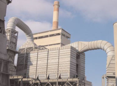
Figure 6.2.1. Electrostatic baghouse for collecting particulates at a cement plant.
THE DEFINITION OF “PARTICULATE MATTER” AND REGULATORY REQUIREMENTS
When the cement industry began applying high efficiency particulate matter controls in the 1960s and early 1970s, particulate matter was defined as all of the material that could be captured by a sampling system operating at a prescribed filtration temperature (120°C ± 14°C in the U.S.). This is now described as total filterable particulate matter, and it includes all particulate matter having a size up to approximately 100 micrometers diameter that can remain airborne in gas stream ducts and stack and thereby reach the test location.
In 1987, the U.S. EPA revised the National Ambient Air Quality Standards (NAAQS) for particulate matter to include only particles with a 50% cut point size equal to or smaller than 10 micrometers (10 µm). This change was made to focus regulatory attention on those particles that are sufficiently small to penetrate into the respirable system and, therefore, contribute to adverse health effects.
In 1997, the U.S. EPA added a new NAAQS applicable to particulate matter with a 50% cut point size equal to or less than 2.5 µm and termed PM2.5.EPA concluded that the PM2.5 NAAQS were needed due to health effects research that indicated that the particulate matter in this size category is most closely associated with adverse health effects.
The health effects attributed to PM2.5 are believed to be due to both their small size and their composition. The small size increases the probability that the particles will penetrate deeply into the respiratory tract and be retained with greater efficiency. The main source of PM2.5 particles is reactions of gases such as sulfur dioxide, nitrogen oxides, and volatile organic compounds. These gases react in the atmosphere over periods of days to form PM2.5 particles.
The regulatory requirements that apply to cement operations and other industrial processes are additive. Both PM10 and PM2.5 emission standards apply in the U.S. Emission limits applied to particulate matter sources continue to be based on total filterable particulate emissions.
In 1999, the U.S. EPA promulgated Maximum Achievable Control Technology (MACT) standards applicable to cement plants. These MACT standards provide additional emission limitations, monitoring requirements, and recordkeeping requirements applicable to kilns, clinker coolers, and other cement plant particulate matter sources. The MACT standard (40 CFR Part 63, Subpart LLL) for nonhazardous waste burning cement kilns became effective in 2002. The MACT Standard (40 CFR Part 63, Subpart EEE) for hazardous waste burning cement kilns became effective in 2003. In both MACT standards, total filterable particulate matter was used as a surrogate for metals emissions that typically comprise 0.2% to 1% by weight of the emissions.
The high efficiency particulate matter control systems used in cement plants are designed to meet and exceed the requirements of this set of environmental regulations.
The range in sizes of particles of concern in particulate matter control is remarkable. Some of the particles generated in clinker coolers and crushing operations have sizes ranging from 1 to 100 micrometers in diameter. Some of the pyroprocessing system generated particles in kilns and precalciners range in size from 0.1 to more than 20 micrometers. To place these sizes into perspec-tive, it is helpful to note that approximately 50 particles of 1 micrometer diameter could be lined up across the diameter of a typical human hair.
Due to differences in particle shape and density, the particle size cannot be adequately described simply by using the diameter of the particle as seen through a microscope. Particles are usually described in terms of the aerodynamic diameter, which is the size of a spherically shaped particle having a density of 1 gram per cubic centimeter having the same aerodynamic properties as the actual particle. This is an especially convenient definition because the aerodynamic particle size is measured directly by most particle sizing techniques. Accordingly, particle sizes specified in envi-ronmental regulations and in particulate matter control equipment tests are defined as shown in Equation 1.
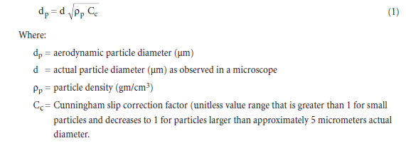
The aerodynamic diameter provides a simple means of categorizing the sizes of particles with a single dimension and in a way that relates to how particles move in a fluid. Unless otherwise stated, particle size is stated in terms of aerodynamic diameters throughout the remainder of this manual.
PARTICLE FORMATION AND SIZE
The range of particle sizes formed in cement plant processes is largely dependent on the types of particle formation mechanisms present. It is possible to estimate the general size range simply by recognizing which of these mechanisms are important in the process being evaluated. The most important particle formation mechanisms in air pollution sources include the following:
• Physical attrition/mechanical dispersion
• Combustion particle burnout
• Homogeneous condensation
• Heterogeneous nucleation
• Chemical reaction
• Droplet evaporation
Physical attrition occurs when two surfaces rub together. For example, the grinding of limestone in the crushers yields particles that break off from both surfaces. The compositions and densities of these particles are identical to the parent materials. The particles formed range from approxi-mately 1 µm to almost 1,000 µm; however, due to the limited energy used in the crushing opera-tion, very little of the particulate matter is less than 10 µm. Physical attrition generates primarily large particles.
Physical attrition is essentially the only particle formation mechanism responsible for the particu-late matter emissions in clinker coolers, conveyors,feed and product storage, bagging operations, rail load-out, truck load-out, and haul road emissions.
Multiple particle formation mechanisms are active in pyroprocessing systems (kilns, precalciners, and alkali bypass systems). Physical attrition continues to be important in the formation and entrainment of feed material introduced into the feed end of cement kilns and preheater towers. In addition, the combustion processes generate ash particles. The combustion-related particles are usually in the range of 0.1 µm to 20 µm in size.
Some organic vapor and ammonia released from the feed stream during initial heating condenses on the surfaces of the physical attrition particles and combustions related particles. This is termed heterogeneous nucleation. The vapor phase material begins to condense once the gas stream reaches the dew point (saturation point) for the specific material. For cement plants, the organic material often has dew points ranging from 425°C down to 90°C. Low concentrations of metal vapors formed during combustion can also nucleate on the surfaces of particles in the kiln effluent gas streams. Heterogeneous nucleation of vapor phase material occurs mainly on particles less than 2 µm.
The quantities of metal vapor and organic vapor available to nucleate on the surfaces of particles are considerably lower in cement pyroprocessing systems than in other combustion sources such as waste incinerators and fossil fuel fired boilers. This is another reason why cement kilns should not be compared with these other types of combustion sources.
Ammonia compounds and organic vapor compounds that remain in the gas phase while passing through the particulate matter control device can nucleate and/or react in the plume to form light scattering particles. The concentrations of these materials are usually quite small. Nevertheless, some facilities can have visible plumes due to this form of particle formation. These plumes are usually termed “secondary” plumes because the material did not exist as particulate matter in the particulate matter control system. Particles formed due to chemical reactions are usually in the range of 0.5 µm to 2 µm.
Some air pollution control systems use solids-containing water recycled from wet scrubbers to cool the gas streams. This practice inadvertently creates another particle formation mechanism that is very similar to fuel burnout. The water streams are atomized during injection into the hot gas streams. As these small droplets evaporate to dryness, the suspended and dissolved solids are released as small particles. The particle size range created by this mechanism has not been exten-sively studied; however, it probably creates particles that range in size from 0.05 µm to 2.0 µm. All of these particles must then be collected in the downstream air pollution control systems.
FABRIC FILTERS
High efficiency fabric filters have been used in the cement industry for more than 40 years. They are used for controlling emissions from cement kilns, clinker coolers, alkali bypass gas streams, finish mills, raw mills, material handling systems, product bagging, and rail load out. Most cement plants have between 40 and 80 separate fabric filter control systems ranging in size from 30 actual cubic meters per minute capacity to more than 100,000 actual cubic meters per minute capacity. There are numerous design types in service.
Operating Principles
Fabric filter operation can be described as three sequential steps:
1. Filtration of particles from the gas stream
2. Gravity settling of the dust cake
3. Removal from the hopper
Each of these steps must be performed properly to ensure high efficiency particulate collection.
In fabric filter systems, particles are removed by 1) inertial impaction, 2) Brownian displacement, 3) electrostatic attraction, and 4) sieving. All four of these mechanisms are active in essentially all fabric filters simultaneously; however, the relative importance of each mechanism differs among fabric filter systems due primarily to the characteristics of the filtration media, the particulate matter size distribution, and the chemical composition of the particulate matter.
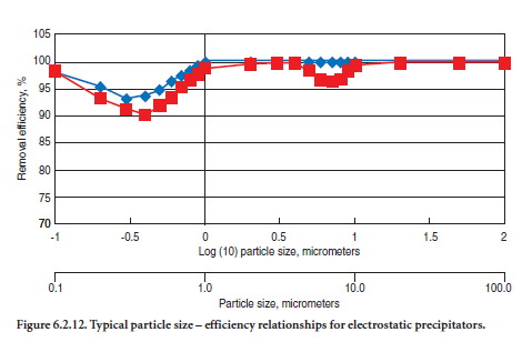
The ability of fabric filters systems to remove particles over the entire size range of industrial concern of 0.1 to 100 micrometers is achieved due to the complementary characteristics of these removal mechanisms. Inertial impaction is highly efficient for large particles and Brownian displacement is efficient for small particles. Electrostatic attraction and sieving can be effective over the entire particle size range. The combined result of these collection mechanisms is a particle size removal efficiency curve illustrated in Figure 6.2.2.
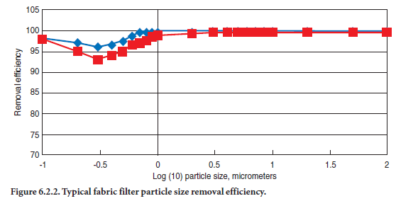
Fabric filters have high removal efficiencies over the entire size range of 0.1 to 100 micrometers. This has important implications regarding the changing regulatory requirements that have been applied to all industrial sources. Sources controlled by fabric filters operate at low PM10 and PM2.5 emission levels. Furthermore, fabric filter systems have very high removal efficiencies even in the particle size range of 0.1 µm to 2 µm subject to the heterogeneous nucleation of vapor phase mate-rials such as metals and organic compounds.
Proper design, operation, and maintenance are needed to achieve the very high removal efficiencies shown in Figure 6.2.2. One of the main design requirements is to provide sufficient filter media in the fabric filter system. The quantity of filtration media is expressed in terms of the air-to-cloth ratio (gross) defined in Equation 2.
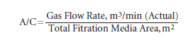
As the air-to-cloth ratio increases, the localized gas velocities through the dust cake and fabric increase. At high air-to-cloth values, some small particles can gradually migrate through the dust layer and fabric. This is possible because dust particles within the cake are retained relatively weakly. After passing through the dust cake and fabric, these particles are reentrained in the clean gas stream leaving the bag. To minimize emission problems related to excessively high air-to-cloth ratios, the design levels are limited. Typical air-to-cloth ratios for various types of fabric filters used in the cement industry are presented later in this chapter.
A second important design requirement is to provide sufficient filtration media cleaning capabil-ity. Routine cleaning of the filtration media is needed to ensure that a portion of the dust is removed from the filtration media surfaces to prevent excessively high gas flow resistance. In most types of fabric filters, agglomerated clumps or flakes of particulate matter are removed from the filter media surface. By allowing the material to agglomerate on the particle surface, the gravity settling of material from the vertical filter media to the hoppers below is facilitated. As indicated earlier, gravity settling of the collected material is an essential second step in the filtration process. Optimal cleaning of fabric filters also requires cleaning on the frequency and intensity most appro-priate for the specific characteristics of the dust cake. Plant personnel operating and maintaining the fabric filters have an important role in ensuring proper cleaning.
The third general design area of importance in all fabric filtration systems is the solids collection and handling systems. Cement plant sources generate relatively large quantities of material that must be collected and transported. Continuous removal of the solids from the fabric filter system is needed to ensure proper operation.
System Design Types
Cement industry sources use a wide variety of fabric filter systems. These are usually classified according to the type of filtration media cleaning technique.
Reverse Air, Negative Pressure. Reverse air fabric filters are used extensively for control of kiln main gas streams and alkali bypass streams. These are primarily negative pressure units in which the main kiln fan is located downstream of the fabric filter. A relatively small number of positive pressure units are in service. These are installed after the main kiln fan and exhaust directly to the atmosphere.
All reverse air fabric filters are divided into a set of compartments operating in parallel. The kiln gas flow through a compartment is stopped during cleaning, and filtered gas is passed in a reverse direction through the bags. This cleaning procedure is the basis for the name “reverse air.” The cleaning system for a reverse air fabric filter is shown schematically in Figure 6.2.3.
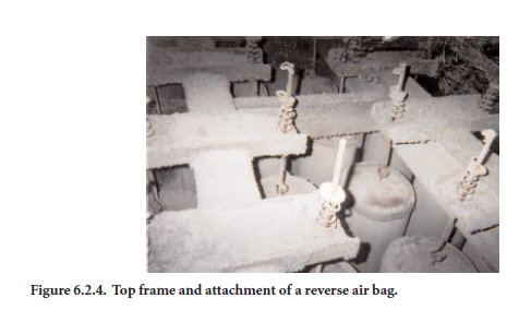
Reverse air bags are hung from support frames near the tops of the compartments. The bags are tensioned to 27 to 54 kg force by spring assemblies on the top frame as shown in Figure 6.2.4. The tension minimizes mechanical flexing and abrasion of the vulnerable fabrics. Most reverse air bags installed in cement kilns have heights ranging from 6 to 9 meters.
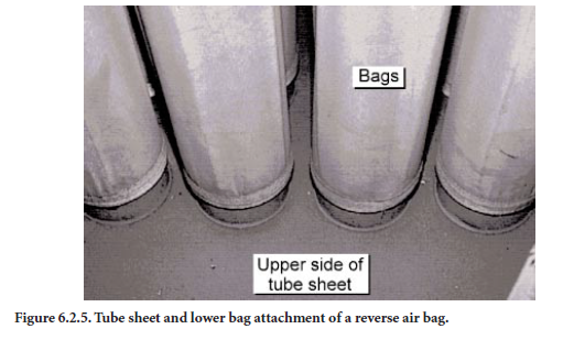
The bags are attached to a metallic plate called a tube sheet that is mounted directly above the hopper. The bags are attached to the tube sheet by means of a clamp and thimble arrangement as shown in Figure 6.2.5 or alternatively a snap ring arrangement. The seal provided by these attach-ments is important in preventing the movement of unfiltered gas to the clean side.
The inlet unfiltered gas stream enters the baghouse near the top of the hopper and then enters the inside of each of the reverse air bags. The dust cake accumulates on the interior surfaces of the bags. The dust cake provides most of the filtration of particles from the inlet gas stream. Bag cleaning must be performed properly to ensure that a residual dust cake remains in the bag to maintain high efficiency filtration, even immediately following a compartment cleaning cycle.
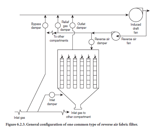
During the filtering mode, the compartment’s outlet and inlet gas dampers are open. When it is time to clean the compartment, the outlet damper is closed to block gas flow. After a short time to allow the bags to relax, the reverse air damper located near the top of the compartment is opened to permit filtered gas from the baghouse outlet to be recycled through the compartment. This reverse flow is sustained for as little as 30 seconds or as long as several minutes. During this time, large clumps of dust cake from the interior of the bags are dislodged and fall by gravity into the hopper. Gravity settling is obviously important during the cleaning operation. Particle movement to the hopper is aided by the reverse gas movement downward in the bag. As long as the reverse air flow rate is adequate (volume and flow time), the particles are carried out of the bag by this gas stream.
The reverse air passes through the compartment’s inlet damper (which remains open during clean-ing) and reenters the duct leading to the inlet side of other compartments, which continue on-line in the filtering mode. Large clumps and sheets of dust cake dislodged during cleaning are collected in the hopper underneath the compartment. Usually, pyramidal-type hoppers are used for dust collection.
Thermal insulation and hopper heaters are used to keep the solids warm until they can be dislodged. Solids discharge valves below the hoppers are needed to prevent ambient air from rush-ing upward into the baghouse.
Most reverse air fabric filters in use in the cement industry use screw conveyors with either rotary discharge valves or double flapper valves to prevent air infiltration. Rotary valves use either metal blades or flexible wipers on metal blades to maintain an air seal. The sections of the double flapper valve move in an alternating fashion so that one is always in place to provide an air seal.
The instruments used on large reverse air fabric filters are often more sophisticated than the instruments on small-to-moderately sized baghouses throughout a cement plant. Often, double-pass transmissometers are used to monitor opacity in the breachings and/or stack downstream from the baghouse. Bag-break detectors are often used when double-pass-type opacity monitors are not required. The bag-break detectors do not comply with agency requirements concerning opacity measurements; however, they do provide a qualitative indication of a change in particulate matter emissions. The signal from the bag-break detectors triggers maintenance attention.
Static pressure gauges mounted across the inlet and outlet of the baghouse measure the overall resistance to flow. These are often termed flange-to-flange static pressure gauges. These instru-ments provide an indication that the unit is operating in a representative manner. These instru-ments do not provide an indication of particulate matter control efficiency.
Static pressure gauges are also used to monitor the pressure of the reverse air stream being supplied to the compartments during cleaning. Inlet and outlet gas temperature monitors are used to ensure that the temperature remains within the acceptable range for the fabric being used.
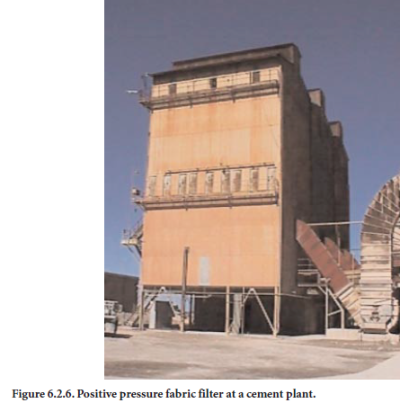
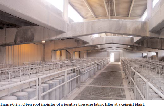
Reverse Air, Positive Pressure Fabric Filters. Reverse air positive pressure fabric filters are installed after the main kiln fan (Figure 6.2.6) and operate at inlet static pressures of up to +8 inches of water. Each of the compartments exhausts directly to the atmosphere.
Each of the compartments is open at the top, and treated gas is discharged through individual compartment stacks, roof monitors spanning the length of the fabric filter (Figure 6.2.7), or a series of roof monitors. During cleaning, the inlet damper is closed, and a reverse air fan is used to draw filtered gas from the top of the baghouse downward in a reverse direction. Usually, the reverse gas flow includes some ambient air that mixes with the filtered gas in the upper portions of the baghouse.
Reverse air positive pressure fabric filters use woven bags identical to those used in negative pres-sure units. The operating temperatures of the positive pressure units are often higher than negative pressure units because air infiltration does not occur in positive pressure units.
Pulse Jet. Pulse jet fabric filter applications in the cement industry include tertiary crushers, material handling operations, finish mills, raw mills, and clinker coolers. At the present time, pulse jets are emerging as a competitive technique for kiln particulate matter control. Pulse jet systems will also be the design approach favored for conversions from electrostatic precipitator units to fabric filtration units for kilns.
There are three major design styles: 1) high pressure, low volume, 2) medium pressure, medium volume, and 3) low pressure, high volume.
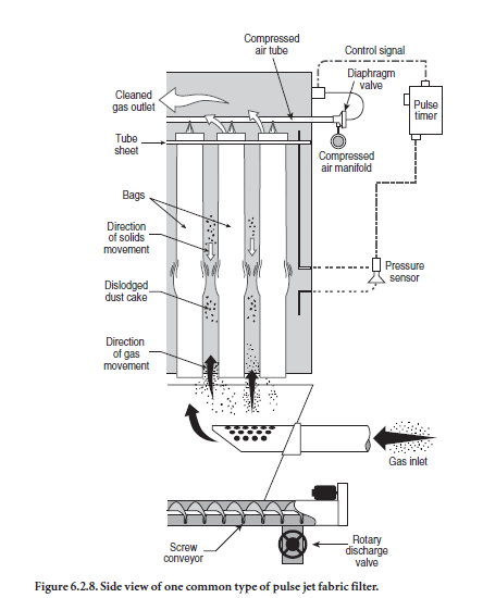
A cutaway drawing of a typical top-access-type pulse jet fabric filter is shown in Figure 6.2.8. The inlet gas stream enters in the upper portion of the hopper and passes vertically up between the bags during filtering.
Dust accumulates on the outside surfaces of the bags shown in Figure 6.2.9. The cleaned gas enters the cylindrical bags and moves upward into the clean gas plenum at the top of the baghouse. The outlet duct from this plenum takes the cleaned gas to the fan and stack.
A portion of the dust must occasionally be removed from the bags in order to avoid excessively high gas flow resistances. The bags are cleaned by introducing a pulse of compressed air at the top of each bag. This pulse provides a source of energy for dislodging the dust cake and, in addition, it induces some reverse air flow into the clean side of the bag. Due to the combined action of the pressure wave and the induced gas flow, the bags are briefly deflected outward. This cracks the dust cake on the outside of the bags and causes some of the dust to fall into the hopper. Cleaning is normally performed on a row-by-row basis while the baghouse is operating.
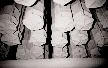
Figure 6.2.9. View of the bottoms of pulse jet bags.
For high-pressure, low-volume-type pulse jets, the compressed air pressures ranges from 60 to 90 pounds per square inch gauge (psig). Medium pressure units range from 30 to 60 psig, and low pressure units have compressed air pressures of less than 30 psig. The quantity of compressed air used in each cleaning cycle is inversely proportional to the compressed air pressure. The diaphragm values used to control the compressed air flow increase in size proportional to the compressed air flow rate. A typical pulse jet system for a high pressure, low volume application is shown in Figure 6.2.10.
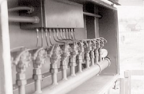
Figure 6.2.10. Pulse jet diaphragm values, compressed air manifold, and solenoid valve NEMA enclosure for a high pressure, low volume application.
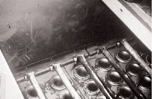
Figure 6.2.11. Compressed air delivery tubes.
Holes are located in the compressed air delivery tube (sometimes termed blow pipes) mounted above each bag as shown in Figure 6.2.11.
The cleaning system controller can operate on the basis of a differential pressure sensor (static pressure drop), or it can simply be operated on a timer. In either case, bags are cleaned on a rela-tively frequent basis with each row being cleaned from once every five minutes to once every several hours.
The bags are supported on metal cages. These cages prevent the bags from collapsing due to the movement of the gas stream through the bags. Because the fabric flexes around the cage wires during filtering, some fabric wear is possible. To minimize this potential problem, cages with closely spaced wires are used for fabrics that are especially vulnerable to flex-type wear. More economical cages are used for fabrics that are very tolerant of flex.
Pulse jet bags hang from a tube sheet and are free at the bottom. There are no frames or attach-ments. This free-hanging design is necessary in order to facilitate bag replacement, to allow gas stream movement upward, and to eliminate any abrasive surfaces near the bottom of the bags.
The pulse jet bags are suspended from a metallic plate called the tube sheet. In top access designs, the bags are clamped and sealed to the top of the tube sheet. This allows for bag removal and replacement from the top of the unit.
Proper cleaning of pulse jet bags is very important to achieve maximum particulate removal effi-ciency and to extend bag service life. Excessive cleaning intensity or very frequent pulsing can physi-cally damage the pulse jet bags, especially near the top where the pulse enters. The compressed air delivery tube is generally mounted close to the bag inlet. Excessive compressed air pressure or a misdirected (non-plumb) pulse can cause damage in the top several meters of the bag.
Compressed air used for bag cleaning can be contaminated by compressor lubricating oil or by condensed water. In order to minimize both compressed air quality problems, it is common for pulse jet collectors to have air dryers on the compressed air supply, coalescing filters for oil removal, and water drains on the compressed air manifolds.
Excessive cleaning intensities and frequencies can cause removal efficiency problems even before bag holes and tears develop. Severe cleaning practices result in the dispersion of small particles or agglomerates of particles from the dust cake. Due to the physical arrangement of the pulse jet bags, it is very difficult for these small particles or agglomerates to settle by gravity into the hopper. Only the large clumps will fall through the gas stream, which is rising upward and opposing gravity settling. The settling problem becomes increasingly difficult near the bottom of the bag because this is the point of maximum gas velocity. Due to the opposed gravity settling, some very small particles or agglomerates with low terminal settling velocities can turn around and return to the remaining dust cake where they will remain until they bleed through the dust cake and the fabric to the clean side of the baghouse.
The instruments used on pulse jet fabric filters are relatively simple. A static pressure gauge is used to measure the overall static pressure drop across the entire baghouse. Other types of instruments that are often used include the following;
• Inlet gas stream temperature monitor
• Outlet gas stream (or fan inlet) temperature monitor
• Compressed air pressure gauge
Pyramidal or trough-type hoppers are usually used on pulse jet baghouses. Units serving hot gas streams usually need thermal insulation and weatherproof lagging in order to keep the collected dust warm and free-flowing. Essentially all pulse jet baghouses need a solids discharge valve that prevents air movement up through the hopper and into the bag area.
Overall, pulse jet fabric filters are relatively small units for a given gas flow rate. This is due to the use of felted type fabrics that can be used at relatively high gas flow rates per unit of cloth. The design air-to-cloth ratios vary from a low of approximately 0.6 (m3/min per m2) to more than 2.5 (m3/min per m2). Generally, units serving sources with small particles have design air-to-cloth ratios in the low end of this range.
In most small pulse units, the rows are cleaned one-by-one while the adjacent rows continue to filter the gas stream. However, with this operating practice, dust released from one row of bags can either return to the bag due to gravity settling problems or be recollected on a bag in an adjacent row that remains in filtering service. Both problems can be avoided by using off-line cleaning. This is accomplished by dividing the pulse jet baghouse into compartments and isolating the compart-ment being cleaned to prevent gas flow.
Plenum Pulse Fabric Filters. A plenum pulse system inherently provides for off line cleaning. In this type of system, all of the bags in a compartment are cleaned simultaneously using a set of poppet valves. After the inlet poppet valve is closed, the cleaned air is introduced through a compressed air manifold poppet. After cleaning, the inlet is reopened to admit the gas stream to be filtered. One advantage of plenum pulse systems is the lack of compressed air tubes above the bags that can impede bag replacement.
Plenum pulse units have design features similar to pulse jet units. The design air-to-cloth ratios are usually 0.6 to 2.4 (m3/min per m2). Pyramidal hoppers are used for dust collection, and screw conveyors are used to transport dust from the systems. The instruments used to monitor perform-ance are identical to those used in pulse jet systems.
Cartridge Filtration. These types of fabric filters are similar to pulse jet fabric filter systems. The filter elements are supported on a tube sheet that is usually mounted near the top of the filter hous-ing. The gas stream to be filtered passes from the outside of the filter element to the inside. Filtering is performed by the filter media and the dust cake supported on the exterior of the filter media.
The unique feature of a cartridge filter is the design of the filter element. Essentially all cartridges are shorter than pulse jet bags. Some cartridges have simple cylindrical designs. Others can have a large number of pleats or other complex shapes in order to increase the filtering surface area. Due to the shortness of the cartridge filter elements, they are usually less vulnerable to abrasion caused by the inlet gas stream. The shorter length also facilitates cleaning using a conventional compressed air pulsing system identical to that used on pulse jet collectors.
Cartridge filter elements are used in a wide variety of industrial applications. Due to their inher-ently compact design, they can be used in small collectors located close to the point of particulate matter generation. They are generally used on gas streams with temperatures less than approxi-mately 135°C. Some specialty materials are available for service up to a temperature of approxi-mately 190°C. Both spunbound and felted material are used. In both cases, the filter media is supported by an inner wire frame or support. The temperature limit is due to the capabilities of the flex resistance of high temperature fabrics and by the limitation of the gasketing material used to seal the cartridge filter element to the tube sheet.
Filtration Media
Woven Media. A woven media is composed of interlaced yarns. The yarns in the “warp” (verti-cal) direction provide strength to the fabric, and the yarns in the “fill” (horizontal) direction primarily determine the filtering characteristics of the fabric. The warp yarns are often monofila-ments because these yarns have high tensile strength and flex resistance. The fill yarns are often spun multifilaments (multiple fibers) that have a bulky surface. The fill yarns may be texturized (roughed-up) by exposing the yarns to a burst of compressed air. This further increases the fiber surface area available for the build-up of particles in the dust cake. The characteristics of the warp and fill yarns partially determine the porosity of the dust cake that accumulates on the surface.
There are gaps between the yarns called pores that can be more than 50 micrometers in size. A portion of this pore area is often blocked by fibers protruding from the yarns. Nevertheless, small particles can pass through these pores until particles are captured on the sides of the yarns and bridge over the openings to form a dust cake. The dust cake is critical for proper filtration by woven cloths. In fact, most of the filtration work is performed by the dust cake, not the woven fabric itself.
Cement plants use woven bags constructed of fiberglass (kilns) and cotton (some cement handling operations). The weight of the filter media varies from 0.3 kg/m2 to 0.5 kg/m2 depending on the yarn and weave characteristics. The heavier weight filter media usually have a longer service life. Woven bags have historically been used primarily on reverse air systems.
Felted Media. Felted media are composed of randomly oriented fibers attached to a very open weave termed the scrim. The fibers are needle-punched to the scrim. The thickness of the felted filter media is controlled, in part, by the number of layers of fibers attached to the scrim. Felted filter media are usually much thicker than woven cloth. The filter weights vary from approximately 14 ounces per square yard to more than 0.9 kg/m2.
There are no pores with this type of filter media construction. The fibers on the filtering (“dirty”) side provide a large number of targets for inertial impaction, Brownian displacement, and electro-static attraction. However, even with felted filter media, the dust cake that accumulates on the surface is primarily responsible for particle capture. Felted filter media are used primarily in pulse-jet-type filtration systems because these materials cannot be adequately cleaned in reverse air systems. Felted filter media composed of Nomex® are frequently used in cement plant applications (clinker coolers, clinker storage and handling, finish mills).
Membrane Media. This filter media is composed of a PTFE® membrane that is laminated to either a woven or felted support fabric. The membrane is placed on the filtering side of the fabric. Particles are collected primarily due to the sieving action of the very small pores (less than 5 micrometers) present in this membrane. In this type of filter media, the dust layer is not especially important in particulate matter removal. Static pressure drop is relatively low due to the good dust cake release properties. Membrane filter media can be used effectively in pulse jet and reverse-air-type filtration systems.
Other Filtration Media. Sintered metal fibers are conceptually similar to felted filter media. Randomly oriented metal fibers are bonded together in a high temperature sintering process. This type of filter media does not require a scrim because the fiber-to-fiber bonds provide sufficient strength to hold the media together. As with the felted cloths, there are no discrete pores through the sintered metal fiber media. In fact, the filter media can be easily mistaken for thin metal sheet-ing. Sintered metal fiber filters are used exclusively in pulse-jet-type filtration systems. This type of filter media is very new and has not yet been used in any U.S. applications.
Ceramic honeycomb filters are cylindrical ceramic blocks with square passageways oriented lengthwise. Some of these passageways open to the inlet side of the filter, and an equal number open to the discharge side. There are several hundred passageways on each side of the cylinder, which is approximately 305 mm in diameter. The filter media are the ceramic walls between the inlet and outlet passageways. The ceramic cylindrical filter element is mounted vertically in a pulse jet filtration system. This is a very new type of filter media, and it has not yet been used in any commercial applications; however, this material may be the filter media of choice in the future.
Filter Media Treatments and Coatings. A variety of treatments and coatings can be applied to a filter media to optimize its properties for a given application. Some of the most common treatments and coatings of interest in cement applications including the following:
• Singeing to minimize the retention of dust cake and thereby improve dust cake release
• Silicon-graphite coatings to minimize fiber-to-fiber abrasion in fiberglass filter media
• Teflon B coatings to minimize fiber-to-fiber abrasion and to minimize acid attack of the fiber-glass filter media
• Acid resistant coatings to protect fiberglass filter media
Filtration Media Capabilities and Costs. The filter media can be composed of a wide range of fabric, membrane, metal, and ceramic materials. The following properties of the filter media are evaluated to determine the appropriate material for a given filtering application:
• High temperature capability
• Acid, alkali, and hydrolysis resistance
• Abrasion-flex resistance
• Dust cake release
• Particulate penetration
• Dimensional stability
• Cost
Table 6.2.1 provides a summary of the general characteristics of various types of filter media that are used in cement applications. More detailed information is available from bag suppliers concerning the specific filter media being considered.
Table 6.2.1. Fabric Capabilities and Costs
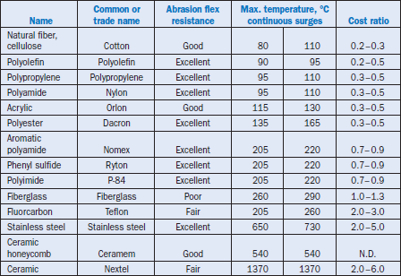
The continuous temperature rating shown in Table 6.2.1 is intended only as a general indicator of the filter media’s capability. To optimize filter media life, the normal operating temperatures should be slightly below this limit. It is usually a good idea to maintain gas temperatures approxi-mately 10°C to 30°C below the continuous temperature limit of the filter media.
The capability of filter media with respect to temperature surges is a function primarily of the media’s dimensional stability and protective coatings. Also, the ability of the filter media to with-stand short term temperature spikes depends on the quantity of dust cake. The dust can absorb some of the heat and, thereby, moderate the maximum temperature while slightly extending the time period that the fabric is exposed to the elevated temperature.
The vulnerability of filter media such as fiberglass with respect to acids is difficult to rate due to the importance of the filter media coating. Overall,however, fiberglass bags should not be exposed to extremely high acid deposition conditions because no coating is 100% efficient for protecting a bag. Therefore, fiberglass bags as a group are considered only fair-to-good for exposure to acids.
If it is necessary to use a chemically sensitive bag, the deposition rates of the chemical should be minimized to the extent possible. Acid compounds in the vapor form do not attack the bags. These acids, such as sulfuric acid, only damage the bags when they condense on the filter media surface or absorb into thin water layers on the surfaces of the media. For these reasons, it is important to keep all areas of the baghouse above the acid dew point temperature and the moisture dew point temperature. It is common practice to keep the entire baghouse 10°C to 30°C above the estimated acid dew point to avoid sulfuric acid related damage. This temperature margin is needed due to the possible variability of the acid dew point temperature, the errors in estimating the acid dew point, and the spatial and temporal variability of gas temperatures in a baghouse.
The ability of filter media to withstand physical abrasion-flex is summarized in Table 6.2.1. The fabrics listed as fair or poor must be cleaned gently, and the bags must be handled carefully during installation.
Most of the filter media have good to excellent capability with respect to abrasion and flex. The two main exceptions are fiberglass and Teflon, which are often used for moderate-to-high gas temperature applications. A variety of the coatings discussed earlier are used on fiberglass in order to improve its abrasion-flex capability.
Most abrasion-flex damage occurs during the cleaning cycle. If it is necessary to use abrasion-flex sensitive materials, the cleaning cycle should be as infrequent and gentle as possible. Overly frequent or overly intense cleaning can lead to very rapid failure of the bags. It is also important to prevent bag-dust abrasion. For sources with a high concentration of large diameter dust (>10 micrometers), a mechanical collector should be located upstream of the unit and/or a blast plate should be installed at the inlet of the baghouse. The blast plate is needed to prevent the rapidly moving (usually 900 to 1,500 m/min) dust from the inlet duct from “blasting” the bags near this inlet duct.
Some filter media are coated to improve their ability to withstand acid attack and abrasion-flex-type physical damage. All fiberglass filter media must have coatings to protect the relatively brittle fibers that can be easily broken by fiber-to-fiber abrasion. Silicone-graphite finishes have been used for fiberglass for more than 40 years. Other coatings that have been developed and used success-fully over the last 20 years include Teflon-B and organic resins. Some of these newer coatings also protect the filter media from acid attack.
The cost of the filter bags (or filter elements) is a major selection criteria. There are considerable differences in the costs of the filter media, and this has a significant impact on the overall cost of the filtration system. The differences in costs are illustrated in Table 6.2.1 using conventional sili-con-graphite-coated fiberglass as an index of 1.0.
Additional factors such as the achievable air-to-cloth ratio and the service life of the filter bag (filter element) should be included in the cost analyses. Accordingly, the cost analyses should be based on the overall annualized cost of the filtration system, not on the cost of the filter media alone.
Filtration Media Tests. A variety of filter media laboratory tests are available to obtain baseline data for new bags being installed in a collector, to evaluate the remaining service life for a set of bags, and to diagnose problems contributing to premature bag failure. The most common tests performed on bags used in cement industry fabric filters include the MIT flex test (primarily for fiberglass bags), mullen burst (primarily felted bags), tensile strength, microscopic evaluation, and acid deposition.
ELECTROSTATIC PRECIPITATORS
The use of electrostatic precipitators (ESPs) for high efficiency particulate matter control began in the early 1950s and increased substantially after the enactment of the Clean Air Act Amendments of 1970. Electrostatic precipitator efficiency and reliability have improved steadily since this time due to research and development programs sponsored by equipment manufacturers, trade associations, and the U.S. EPA. Data compiled as part of a PCA-sponsored compilation of emission test data for the cement industry indicate that the electrostatic precipitators that remain in service operate with emission rates that are similar to reverse air fabric filters. It is anticipated that ESPs will continue to provide high efficiency particulate removal in cement kiln applications for many years.
The use of electrostatic precipitators might increase in the future due to the recent application of wet ESPs for mist eliminator service. Small ESP systems on the outlet of SO2 scrubbers might contribute significantly to the control of reentrained solids from the scrubbers.
Operating Principles
In all electrostatic precipitators, there are three basic steps to particulate matter capture.
• Step one is the electrical charging and migration of particles toward a vertical collection surface.
• Step two involves the gravity settling (or draining in the case of liquids) of the collected mate-rial from the vertical collection surfaces.
• Step three is the removal of the accumulated solids or liquids from the hopper or sump below the electrically energized zone.
With respect to the three basic steps, electrostatic precipitators are very similar to fabric filter systems discussed earlier.
The purpose of the high voltage equipment of an electrostatic precipitator is to cause particle-charging and migration (Step 1). In the primary control cabinet, the automatic voltage controller, the SCRs, and the SCR trigger/pulse controller alter the A.C. line voltage and adjust the waveform of the voltage to control electrical conditions on the primary side of the transformer in the trans-former-rectifier (T-R) set. The result is a primary voltage that can range from zero to more than 400 volts.
In the transformer located on the roof of the ESP above each field, the relatively low primary volt-age is stepped up to a secondary voltage of more than 50,000 volts.
The electricity on the secondary side of the transformer is converted from alternating current to direct current in a rectifier located in the T-R set. As a result of the T-R set, the electrical power going to the discharge electrodes is a pulse-type direct current.
The corona electrical discharges on the precipitator discharge electrodes are needed to electrostati-cally charge the particles. Within this corona discharge, electrons accelerated by the very strong electrical field strike and ionize gas molecules. Each collision of a fast-moving electron and a gas molecule generates an additional electron and a positively charged gas ion. The corona discharges are often described as an electron “avalanche” because large numbers of electrons are generated during multiple electron-gas molecule collisions. The positive ions generated in the ionization process move back toward the discharge electrode and are neutralized.
Some of the electrons released in the corona discharges are later captured by gas molecules in areas slightly farther away from the discharge electrode where the electrical field strength is lower. These negatively-charged gas ions move rapidly toward the grounded collection plates.
Some of the negatively charged gas ions are captured by particles as the ions attempt to move toward the grounded collection plate. The particles quickly reach a maximum charge called the field dependent saturation charge. This is the charge at which the electrical field created by the captured ions is strong enough to deflect additional gas ions that are approaching the particle. The magnitude of the saturation charge is dependent on the particle size, as indicated by Equation. 3.
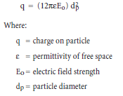
Small particles have a low saturation charge because the ions are bunched closely together on a small surface. As shown in Equation 3, the saturation charge increases with the square of the parti-cle diameter. Large particles are easier to collect in electrostatic precipitators because they accumu-late higher electrical charges on their surface and, therefore, are more strongly affected by the applied electrical field.
Diffusion of the negatively-charged gas ions to the surface of the particles can increase the electri-cal charge above the level created by the field dependent charging. This charging mechanism, usually termed diffusional charging, is important primarily for particles of less than 2 µm (MacDonald and Dean, 1980).
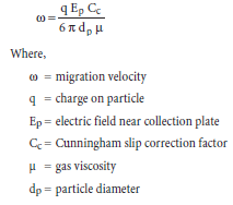
Once the particles have attached ions with a negative electrical charge, the particles are influenced by the strong, nonuniform electrical field between the discharge electrode and the grounded collection plate. Accordingly, the charged particles begin to migrate toward the grounded plates. Large particles move faster than small particles due to the greater electrical charge on the large particles. The migration velocities of particles are indicated in Equation 4.
The field strength at the discharge electrode is dependent primarily on the peak voltage applied to the discharge electrodes. The field strength at the collection surface depends on the applied peak voltage and on the electrical field created by the negatively charged ions streaming toward the collection plates along the electrical field lines. The electrical field created by the negative gas ions is termed the ionic space charge.
The combined effect of field dependent charging and diffusional charging creates a typical particle size collection efficiency relationship similar to Figure 6.2.12. Very high collection efficiencies exist above 0.5 micrometers due to the increasing effectiveness of field dependent charging for large particles. Diffusional charging is especially beneficial for particles less than 0.1 µm. There is a diffi-cult-to-control range between 0.1 µm to 0.5 µm due to the size dependent limitations of both of these charging mechanisms. As indicated in Figure 6.2.12, the precipitator is least effective for the particles in this size range.
The extent of this efficiency limit in the difficult-to-control size range is related to the size of the precipitator, the extent of sectionalization, the operating conditions, and the physical conditions. Well-designed and operated precipitators can have size-efficiency relationships with only a slight efficiency decrease in the difficult-to-control size range. Undersized precipitators or units in poor condition can have a more pronounced efficiency decrease in this size range.
System Design Types
There are two basic types of electrostatic precipitators that will be applied to cement industry sources: 1) dry, negative corona, multi-field units, and 2) wet, negative corona, single field units.
Negative corona, multi-field units. Adry,negative corona electrostatic precipitator consists of a large number of parallel gas passages with discharge electrodes mounted in the center and grounded collection surfaces called plates on either side. The discharge electrodes are spaced 114 to 152 mm. away from each of the collection plates as shown in Figure 6.2.13. A high negative voltage is applied to the discharge electrodes. The voltage causes continuous electrical discharges termed coronas.
Figure 6.2.13. Gas passage composed of discharge electrode and collection plates.
Negatively-charged gas ions formed in and near the corona discharge impart an electrical charge to the particles and cause them to be repelled over to the electrically grounded collection plates. Mechanical hammers called rappers are used to remove a portion of the dust layer accumulating on these plates and the small quantities of
dust that also collect on the discharge electrodes. Particle agglomerates and dust layer sheets fall by gravity into the hoppers during rapping.
Dry, negative corona electrostatic precipita-tors, such as used on cement kiln, alkali bypass, and clinker cooler sources are often designed for gas flow rates from 1,400 to more than 9,000 m3/min.
The gas stream passing through the duct to the precipitator is moving too fast for treat-ment. Deceleration occurs in the inlet nozzle section immediately upstream of the precipi-tator. The gas velocity decreases by a factor of approximately 10 so that the average velocity is usually between 1 to 2 meters per second.
In addition to slowing down the gas stream, the inlet nozzle is used to distribute the gas flow as uniformly as possible so that there are no side-to-side or vertical variations in the gas velocities at the entrance of the precipitator.
Proper gas distribution is achieved by proper inlet nozzle design, proper inlet ductwork design, turning vanes in the inlet nozzle, and a series of gas distribution screens mounted in the inlet nozzle.
As the gas stream enters the precipitator, it goes through passages formed by the large, parallel collection plates. High voltage discharge electrodes are centered between each of the plates. In this precipitator, small diameter wires serve as the discharge electrodes. In other precipitator designs, rigid masts or wires in rigid frames are used. The high voltages applied to the discharge electrodes create localized electrical discharge points called coronas. Negative gas ions are formed in the coro-nas. These ions cluster around the particles attempting to move through the precipitator passages.
Once the ions are on the particle surfaces, the particles are affected by the electrical field that exists between the high voltage discharge electrodes and the electrically grounded collection plates. Accordingly, the particles migrate over to the plates and build up as dust layers on the plate surfaces. A small fraction of the particulate matter also accumulates on the discharge electrodes.
The discharge electrodes are divided into fields. These fields are portions of the precipitator ener-gized by a single T-R set power supply. Most units have three to four fields in series. The precipita-tor can also be divided into separate chambers that are separated by a solid wall. Chambers may also be designed as separate precipitator shells.
Each of the fields is energized by a T-R set. The primary control cabinet circuitry controls the volt-age in the alternating current power line applied to one side of the transformer in the T-R set. The high voltage generated in the transformer is converted into direct current in the rectifier and then sent to the precipitator field.
The primary control cabinet includes silicon-controlled rectifiers (SCRs) – also known as thyris-tors – to control the alternating current line to the T-R set. These SCRs are controlled by an auto-matic voltage controller that maintains the unit at the maximum voltage possible and by the SCR trigger and pulse controller that adjust the waveforms. The following list includes other major electrical components in the primary control cabinet:
• Linear reactor to control normal current surges
• Under-voltage protection to protect against short circuits
• Indicator gauges to provide data concerning the electrical operating conditions in the field
The gauges on the control cabinet for each T-R set provide much of the data necessary to evaluate performance. Some new precipitators have digital gauges used either alone or in combination with the analog gauges.
The distance between the high voltage discharge electrodes and the grounded collection plates affects the electrical charging and migration of the particles. If some portions of a discharge elec-trode and a collection plate are closer than others, a spark will occur frequently at the close approach point. The automatic voltage controller will respond to this condition by reducing the applied voltage. This reduces the affected field’s ability to electrically charge and collect particles. For example, if the designer’s intended discharge electrode spacing to the collection plates is 114 mm, it is usually necessary to maintain all the discharge electrodes at this point with an allowable spacing deviation of only ± 13 mm. All discharge electrodes must be between 101.6 mm and 127.0 mm away from all portions of the adjacent collection plates. This is not easy to maintain.
The discharge wires are suspended between the grounded collection plates using insulators called high voltage frame support insulators. There are usually at least two high voltage frame support insulators for each bus section in a field.
The accumulation of moisture or dust on the surfaces of these support insulators can cause a short circuit. These shorts start as a small current and are identified by reduced voltage in the field and reduced spark rates. As the current flow increases, it heats the surface of the insulator. This heating can cause the insulator to shatter. The development of a short circuit across the insulator surface can also cause the field to automatically shut down. The high voltage frame support insulator must be kept clean at all times to prevent these problems.
Electrical heaters are often used around each insulator to reduce moisture accumulation. Purge air blowers are used to provide a constant flow of hot air into the insulator penthouse or compart-ment. This hot air flows through holes in the insulator top cover in order to purge out the interior area of the insulators.
Several anti-sway insulators are usually installed at the bottom of each high voltage frame to prevent a pendulum action that reduces clearances between the high voltage electrodes and the grounded plates. The anti-sway insulators must inherently be located in the hopper area where it is impossible to provide supplemental heat or hot purge air. Accordingly, these insulators are vulner-able to electrical leakage and failure. Shortcircuits are normally minimized by using relatively long insulators.
Movement of the wire-type discharge electrodes is minimized by hanging bottle weights on each wire. These provide 11-14.0 kgf of tension on the wire so that it does not move excessively. In other precipitator designs, the discharge electrodes are mounted in rigid frames or are constructed as rigid masts.
The hoppers have very steep slopes to facilitate solids movement into the solids discharge valves leading out of the hoppers. A center division plate is used in each hopper to prevent untreated gas from evading the electrically energized zone by passing through the upper regions of the hopper. This is termed the anti-sneakage hopper baffle. There are also hopper heaters to keep solids hot to facilitate hopper discharge.
The side walls of the precipitator also have anti-sneakage baffles to prevent untreated gas from pass-ing along the side walls of the precipitator where it is impossible to mount discharge electrodes.
The rapping systems are especially important compo-nents of a precipitator. Separate groups of rappers are used to clean the collection plates, discharge electrode frames, and gas distribution plates. There are two basic categories of rappers: 1) roof-mounted rappers, and 2) side-mounted rappers. With roof-mounted rapper designs, there are a large number of individual rappers, each connected to a single high voltage discharge elec-trode frame or a section of collection plates. For collec-tion plate rappers, the energy of roof-mounted rappers, as shown in Figure 6.2.14, is transmitted down a metallic rod. For discharge electrodes, the energy must be trans-mitted through an insulator rod to prevent carrying high voltage to the rapper and the accessible areas on the roof of the precipitator.
Figure 6.2.14. Roof-mounted rapper.
In a side-mounted rapper system, motors are mounted on the exterior of the precipitator. These motors turn shafts that run across the precipitator. A set of hammers is mounted to these rotating shafts in order to rap each individual collection plate and discharge electrode frame.
For both types of rapper designs, the frequency and intensity of rapping must be carefully controlled in order to achieve proper precipitator removal efficiency. The frequency of rapping must take into account that approximately 50% – 80% of the particulate is removed in each separate field. Accordingly, the inlet fields remove much greater quantities of dust than the outlet fields.
One or more opacity monitors are usually located at the outlet of the precipitator. These are espe-cially useful for evaluating performance of electrostatic precipitators. The opacity data are used in conjunction with the electrical data from each of the fields to diagnose problems.
Rigid discharge electrode frame electrostatic precipitators were developed in Europe and began to be installed in the U.S. in the late 1970s. Most rigid frame designs have small diameter discharge electrode wires that are firmly mounted between tubular frames mounted in gas passages. Many units rebuilt during the 1980s included rigid frames. This design approach eliminated the need for wire bottle weights to provide the proper wire tension. The rigid frame design also substantially decreases wire swaying during rapping and thereby contributes to more stable electrical operation.
Additional space between the plates is needed to accommodate the discharge electrode support frames. Usually, the plate-to-plate spacing is increased to 279 mm -305 mm instead of the 229 mm spacing common in conventional weighted wire designs. This additional space allows for clearParticulate Matter Control
ances between the discharge electrode frame and electrically grounded collection plates of 100 to 125 mm, values typical of weighted wire-to-plate spacings in conventional units.
One additional advantage of rigid frame electrodes has been the improved energy transmission during discharge electrode rapping. This improvement minimizes the accumulation of solids on discharge electrode wires. The development and refinement of rigid frames is one of a number of design improvements that have contributed to increased efficiency and reliability of electrostatic precipitators.
Electrostatic precipitator theory developed more than 30 years ago suggested that increased plate-to-plate spacing would improve precipitator efficiency by allowing higher peak secondary voltages. Units with increased plate-to-plate spacing began to be installed in the late 1970s and early 1980s as part of the trend toward rigid frame designs. Due to the interest in the performance advantages of wide spacings, some units were installed with plate-to-plate spacings considerably larger than those needed simply to accommodate rigid frames. The trend toward wide spacings is expected to continue in the future due to the success of this design change.
Some electrostatic precipitator applications in the cement industry are limited by high dust layer resistivities. Due to the inability to adequately conduct electrical current through the dust layer, the voltage on the dust layer exterior surface increases and reduces the ability of the precipitator field to electrically charge and migrate particles to the dust layer surface.
High resistivity conditions can be significantly minimized by design changes in the power supply. Pulse energization systems provide a very short term, high voltage spike. This allows for increased particle charging without increasing the total current flow passing from the discharge electrodes across the interelectrode space to the surface of the dust layer. Peak secondary voltages of up to 75 kV can be generated for periods of 5 to 20 milliseconds.
Pulse energization systems are applied when conventional means to minimize high resistivity are not possible or are not highly effective. These conventional techniques include changes in the inlet gas stream temperature and changes in the inlet moisture levels. Because both of these conven-tional approaches are limited in cement applications, pulse energization systems are often applied.
Wet, Negative Corona Precipitators. Wet, negative corona precipitators are one of several types of collectors competing for mist eliminator applications of kiln SO2 systems. It is too early in the application of SO2 control systems in the cement industry to determine if wet, negative corona precipitators will be used extensively to control the emission of solids-containing droplets reen-trained from the SO2 scrubbers. Control of the reentrainment emissions might be needed to reduce overall emissions to the atmosphere or to protect the fixed beds of regenerative thermal oxidizers used in some cement plants after the wet scrubbers.
A wet, negative corona precipitator used as a mist eliminator can consist of a set of vertically oriented tubes or concentric passages used as collection surfaces. Energized discharge electrodes are suspended from insulators and centered in the tubes or passages. Alignment of the negatively charged discharge electrodes and the electrically grounded collection surfaces is very important to ensure that the field can operate at the necessary voltage. The alignment tolerances are similar to those for dry precipitators. The power supplies are essentially identical to those used on dry, nega-tive corona precipitators.
An electrode washing system rather than rappers is used for dust removal. Recirculation liquid must be purged to maintain the solids levels. The rate of liquid purge depends primarily on the rate of collection of solids. Usually, the rate of purge is quite small because the overall recirculation rate of liquid is quite small. A normal liquid-to-gas ratio for a wet, negative corona precipitator is less than 0.2 m3 liquid per m3 gas.
Wet, negative corona ESPs used in general industrial applications are often preceded by a quench chamber to ensure the gas stream is saturated prior to entering the unit. This quench chamber can either be a separate stand-alone vessel, or an initial compartment within the wet ESP itself. This quench chamber is unnecessary when the unit is downstream of a SO2 scrubber and is being used strictly for control of scrubber reentrainment emissions. The gas stream exiting the SO2 scrubber is sufficiently humidified and the vulnerability to drying of solids on the collection surfaces of the wet precipitator mist eliminator is very low.
Wet precipitators used for mist eliminator service will be limited to a single small field. This provides a sufficient collection area because the solids-containing droplets being controlled are large and, therefore, easily charged.
PERFORMANCE ISSUES CONCERNING FABRIC FILTERS AND ELECTROSTATIC PRECIPITATORS
PM10 and PM2.5 Emission Rates
The Portland Cement Association and its member companies have undertaken a study of PM2.5 and PM10 particulate emissions from cement plants to compile accurate emission factor data (Richards and Holder, 2000). The scope of the testing program included cement kilns, alkali bypass streams, clinker coolers, finish mills, raw mills, coal mills, silos, bagging operations, and loadout operations. Many of the sources tested used fabric filters for particulate matter control. These data provide an up-to-date indication of the performance of fabric filters and electrostatic precipitators in various cement industry applications.
To ensure consistency of the data, a recently developed PCA emission test protocol was used at the plants participating in the program. This protocol was developed for PCA by Air Control Techniques, P.C. (Richards 2002) based on draft EPA PM2.5 test procedures released in 1989. The testing procedure specified in the PCA Protocol was developed because the U.S. EPA has not yet promulgated a PM2.5 emission test reference method for stationary sources. The PM2.5 and PM10 data were obtained simultaneously using a dual cyclone sampling train (see Figure 6.2.15) operated in a manner consistent with U.S. EPA Method 201A.
The sampling times are selected to ensure that there are adequate particulate catch weights in each particulate size category to allow for chemical analyses.
The results of tests conducted at five cement plants shown in Table 6.2.2 indicate that the emis-sions of filterable PM10 are approximately one-sixth of the value of the limited PM10 emission
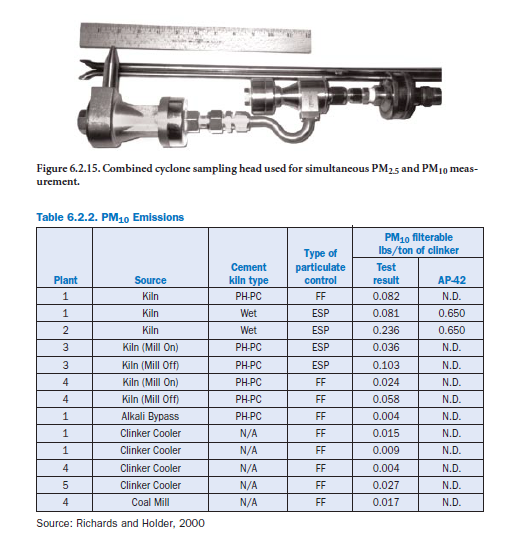
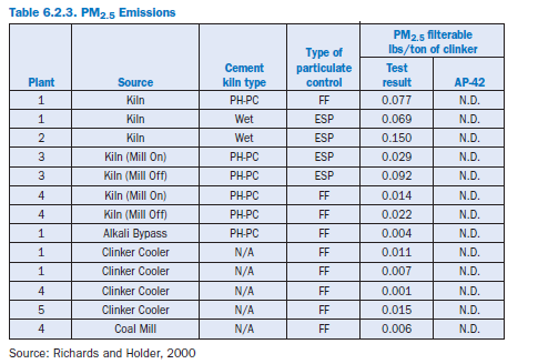
factor data published in the Fifth Edition of AP-42, Section 11.6. The measured emissions of filter-able PM2.5 were very low. The air emission test data shown in Table 6.2.3 compiled from 1997 to 1999 for the PCA test program represent the most accurate and complete analyses of portland cement industry particulate emissions that are presently available. These data will be helpful in the development of PM2.5 implementation programs.
Fabric Filter and Electrostatic Precipitator Comparisons
The PM10 and PM2.5 data summarized in Tables 6.2.2 and 6.2.3 indicate that both fabric filters and electrostatic precipitators reduce emissions to low levels. The data applicable to the relatively few electrostatic precipitators tested to data for PM10 and PM2.5 emissions suggest that emissions are slightly higher than those of fabric filters; however, this difference is probably due to the represen-tativeness of the units tested to date.
Fabric filters and electrostatic precipitators as applied in the cement industry appear to have very similar performance for total filterable particulate matter. As indicated by the large data base analyzed by PCA in 1996 (Richards 2002), the emissions from fabric filter and electrostatic precipitator kilns were very similar. A comparison of the distributions of the 111 filterable partic-ulate matter emission test results summarized in the PCA document are provided in Figures 6.2.16 and 6.2.17.
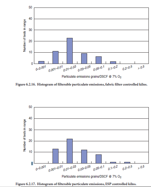
For fabric filter controlled kilns, the median value of the particulate matter tests was 0.031 mg/m3 @ 7% O2, and the standard deviation was 0.048 mg/m3 @ 7% O2.For electrostatic precipitators, the median value of the particulate matter tests was 0.039 mg/m3 @ 7% O2, and the standard devi-ation was 0.070 mg/m3 @ 7% O2.These differences are not statistically significant.
Changes in Operating Conditions Caused by PCDD-PCDF Related Reductions in the Inlet Gas Temperatures
Acid Corrosion. Cement kilns gas streams usually have extremely low sulfuric acid concentra-tions and low-to-moderate hydrogen chloride concentrations. Also, the gas stream contains high concentrations of alkaline particulate matter. Accordingly, fabric filters and electrostatic precipita-tors serving cement kilns are not as vulnerable to low temperature related acid attack as systems serving many other types of industrial sources.
Despite these favorable characteristics, operators of pyroprocessing system fabric filters must remain aware of the potential for acid attack in localized areas of the unit. Increased acid attack problems are now being created by the reduced gas temperatures and increased moisture levels resulting from the increased use of evaporative cooling to achieve PCDD-PCDF limits in the MACT standards. Acid attack is most likely in exterior corners of exposed compartments, in hoppers, and in reverse air return ducts. Acid attack throughout the fabric filter and electrostatic precipitator systems can be caused by air infiltration into negative pressure (fan after the fabric filter) units.
Routine internal inspections and occasional bag laboratory tests provide an effective means to identify the onset of acid attack corrosion problems.Furthermore, gas stream temperature moni-tors on the outlet of the fabric filter and electrostatic precipitator can be compared with the inlet temperature monitors required by the MACT standard. Low outlet temperatures, especially during in-line raw mill on conditions, should be routinely checked. Furthermore, the gas temperature drop across the fabric filter system should be routinely monitored for changes that exceed the routine variability associated with seasonal factors.
Electrostatic Precipitator Resistivity. Resistivity is a measure of the ability of the electrical charges to move through the dust layers on the collection plates and discharge electrodes. When the resistivity is low, the electrical charges are conducted very readily and only a slight electrostatic field is maintained across the dust layer. When the resistivity is high, the electrical charges have difficulty moving through the dust layer, and they create a very high electrostatic field as they accu-mulate on the outer surface of the dust layer.
Precipitators work best when the extremes of these spatial and temporal distributions of the dust layer resistivities remain within the moderate range. This range is often defined as 1×10⁹ ohm-centimeters to 5×10¹⁰ ohm-centimeters. This is a very narrow operating range, and it is not always possible to remain within these limits due to routine variations in process operating conditions, raw material characteristics, and fuel characteristics.
Two general mechanisms for electrical charge conduction that determine the overall resistivity of the dust layer: 1) bulk conduction, and 2) surface conduction. The rate of bulk conduction depends strongly on the particle temperature. As the temperature increases above 180°C to 260 °C, most cement kiln dust particles become more electrically conductive. The composition of the particles also influences the rate of bulk conduction. Sodium ions, potassium ions, sulfate ions, and some carbonaceous compounds are especially good electrical charge carriers. Accordingly, the rate of bulk conduction depends on both the gas stream temperature and the particle composition. The sodium and potassium ion concentrations can vary due to changes in the volatilization-nucleation concen-tration loops that exist in suspension-preheater-type kilns. The sodium and potassium concentra-tions also vary due to changes in the limestone, shale, and additive materials used to prepare the raw meal. The chloride concentration of the cement kiln dust has also been identified as a factor in determining the resistivity. As in the case with sodium and potassium ions, chloride concentrations can vary significantly on a day-by-day basis due to changes in the raw materials.
Surface conduction of electrical charges is dependent almost entirely on vapor phase materials that condense or adsorb on the particle surfaces. Mass transfer of vapor to the particle surfaces is highly gas temperature dependent and increases rapidly as the gas temperature decreases below 200°C. Due to this mode of electrical charge conduction, the resistivity decreases as the gas stream is cooled below 200°C as shown in Figure 6.2.18. Factors affecting the surface conduction mechanism of electrical
charge transport include the moisture content, the sulfuric acid vapor content, 12 and the organic vapor content. The source of organic vapor is volatilized material being fed to the inlet side of preheater kilns.
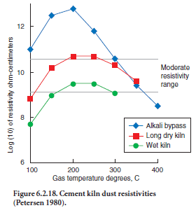
A set of resistivity curves published by Petersen (1980) is shown in Figure 6.2.18. Petersen’s data indicate peak resistivities between 180°C to 300°C. There are significant resistivity differences due to the moisture levels present in the gas streams of different types of pyroprocessing operations. Wet process kilns often have moisture levels of 30% to 35%, while long dry kilns, preheater kilns, pre-heater-precalciner kilns, and alkali bypass streams can have moisture levels of less than 5% to 10%.
Due to these resistivity-temperature relationships, the electrostatic precipitators designed for long dry kilns, preheater kilns, preheater-precalciner kilns, and alkali bypass streams may be designed for gas temperatures between 120°C and 180°C where the resistivities are in the moderate range. The electrostatic precipitators for wet kilns are usually designed for temperatures between 260°C and 380°C where resistivities are again in the moderate range. Changes to colder gas temperatures for units operating above 200°C in order to achieve PCDD-PCDF emission limits in the MACT standards might have an adverse impact on particulate control efficiency due to the change in resistivity.
Parameter Monitoring
The development of Compliance Assurance Monitoring (CAM) requirements and other similar regulatory programs has increased interest in the use of particulate matter control system operat-ing parameters as indicators of performance. In the case of fabric filters, regulatory agencies have expressed interest in the use of static pressure drop data. For electrostatic precipitators, data concerning the electrical power input to the fields have been requested from operators. In both cases, there are significant limits to the usefulness of the data for evaluating particulate matter control system performance and emissions.
Fabric Filter Static Pressure Drop Data. This operating parameter provides only the most general indication of fabric filter system performance. In fact,within the normal operating range of approximately 5 to 200 mm W.C., changes in the overall static pressure drop (flange-to-flange) have only a limited relationship to emissions. The static pressure drop usually becomes significant with respect to particulate matter emissions only when the static pressure drop is extremely low (i.e., less than 5 mm W.C) or extremely high (i.e., greater than 200 mm W.C.)
Decreases in static pressure drop within the range of 50 to 200 mm W.C. can occur due to one or more of the following factors:
• Decreased gas flow rate
• Decreased dust quantities on the bags due to changes in cleaning practices
• Missing bags, bag holes, and bag tears
Decreased gas flow rates and moderate changes in the quantities of dust on the filter media surface rarely have any impact on emissions. Missing bags, bag holes, and bag tears can have a significant impact on emissions. Unfortunately, the static pressure drop data are not sufficient to determine which of the three is responsible for the observed change. Of the three main factors affecting static pressure drop, the static pressure drop values are less sensitive to missing bags, bag holes, and bag tears.
Low resistance paths for gas flow are created when there are missing bags or when holes or tears develop in the bags. Gaps in bag sals or in the welds around the tube sheet also create paths for unfiltered gas to pass through the baghouse. As shown in 6.2.19, the fraction of the total gas pressure drop across the opening is equivalent to the average pressure drop across the undamaged bags in the compartment.
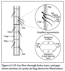
The resulting overall static pressure drop measured by the fabric filter instrumentation is very close to the pre-tear pressure drop except in cases where the area of the hole (or holes) is very large. The velocities and gas flow rates through these holes, tears, and gaps can be quite high. Accordingly, the measured static pressure drop is not a good indicator of the presence or absence of holes and tears.
High static pressure drop values exceeding 200 mm W.C. can be caused by severe blinding of the filter media and/or failure of the unit cleaning system (i.e., reverse air or pulse jet cleaning system components). Blinding can be caused by the carryover of liquid droplets from the evaporative cooling tower or inlet spray nozzle system used to minimize inlet gas stream temperatures and PCDD-PCDF formation. Failure of the cleaning system can occur due to a variety of mechanical faults affecting a single compartment or numerous compartments. Particulate matter emissions usually increase at high static pressure due to the seepage of fine particles through the dust cake and filter media. Seepage emissions due to high static pressure drop rarely persist for long time periods because the high static pressure suppresses gas flow through the system and causes fugitive emissions from the process equipment. The localized fugitive emissions are usually identified and corrected quickly.
Electrostatic Precipitator Electrical Power Input Data. Regulatory agencies have occa-sionally requested that the total power input to an electrostatic precipitator be used as a monitor-ing parameter in CAM programs. The total power input is calculated based on the secondary voltages and secondary currents to each of the fields in the unit. Unfortunately, the total power input has a complex relationship with particulate matter emissions.
For electrostatic precipitators subject to moderate-to-high resistivity, particulate matter emissions increase as the power input decreases. Unfortunately, the correlation between emissions and power input is not precise or sensitive. It is very difficult to estimate changes in particulate matter emis-sions based on decreased power input levels.
For electrostatic precipitators subject to low resistivity, particulate matter emissions increase as the power input increases. This relationship is the inverse of the relationship prevailing during high resistivity conditions. There is no direct means to determine if the dust layer resistivity throughout the unit has shifted or if localized portions of the precipitator dominated by either high or low resistivity. Accordingly, it is difficult to interpret changes in power input with respect to particulate matter emissions.
Another limitation to the use of power input data is the very indirect fundamental relationship between particulate matter emissions and power input. The performance of the precipitator is related more to the “quality” of the electrical operating conditions than to the total power input. Furthermore, emissions of particulate matter are a function of a number of highly interrelated variables that include (1) electrical operating conditions, (2) rapping conditions, (3) gas flow rate conditions, (4) physical design characteristics, and (5) hopper discharge conditions. No single parameter, such as power input, provides sufficient information to evaluate changes in particulate matter emissions.
Secondary Plumes
The presence of a secondary plume at the kiln stack is usually indicated by in-stack opacities of 1%to 10% measured by a continuous opacity monitor and plume opacities of greater than 20% meas-ured by a visible emission observer. The following characteristics apply to the majority of second-ary plumes observed at cement plants (Richards, 1999):
• The secondary plume is detached from the stack or vent, or forms after the effluent gas stream passes the opacity monitor on the stack. The difference between the in-stack opacity and the plume opacity is quite large.
• The frequency of plume appearance and the intensity of the plume opacity are not related to the operating characteristics of the high efficiency control device used to treat the effluent gas stream at the source.
• The primary particulate matter that is penetrating the high efficiency particulate matter control device is at relatively low levels, thereby making it possible to see the detached charac-teristic of the secondary plume. The secondary plume does not dissipate after condensed water, if present, re-evaporates into the atmosphere.
• The secondary plume is most common during periods of low ambient temperature and/or high ambient relative humidity.
The possible reaction mechanisms contributing to the formation of secondary plumes at cement kilns include: 1) the homogeneous gas phase reaction between ammonia and hydrogen chloride, 2) the homogeneous gas phase reaction between ammonia and sulfur dioxide, 3) the reactions between sulfur dioxide, ammonia, and hydrogen chloride in droplets, and 4) the condensation of organic compounds.
The counterflow contact between the main kiln gas stream and the incoming raw materials creates the potential for the introduction of vapor phase compounds into the gas stream from compounds that enter with the cold raw materials. These vapor phase compounds can be released to the gas stream due to volatilization and/or chemical breakdown of naturally occurring chemicals and remain in the gas stream (Gartner and Wilk, 1984; Cheney and Knapp, 1986). Naturally occurring organic compounds and nitrogen-containing compounds in the limestone, shale, sand, and other raw materials can introduce ammonia gas and organic compounds. The ammonia compounds can react with hydrogen chloride and/or sulfur dioxide after the gas stream is released from the stack. The organic compounds can nucleate to form organic particulate matter once the gas stream is released from the stack. Secondary plume formation at cement kilns is due to the presence of these constituents and it is not related to the performance of the kiln fabric filter or other high efficiency particulate matter control device.
Condensable Particulate Matter Emissions
Some regulatory agencies have requested that industrial sources, including cement plant operators, provide emissions data concerning condensable particulate matter emissions. This is material that is present in the effluent gas stream in the form of vapor phase compounds that pass through the filters maintained at temperatures of 41°C to 56°C in EPA reference method sampling trains. These vapor phase compounds can nucleate to form particles once the effluent gas stream is released to the atmosphere and cools to ambient temperatures. The emissions that are measured as condensa-ble particulate matter include volatile organic compounds, semi-volatile organic compounds, sulfuric acid, nitric acid, and ammonium compounds. All of these categories of emissions are usually at low levels in cement pyroprocessing system gas streams.
Fabric filters and electrostatic precipitators are not designed to remove condensable particulate matter. The material must nucleate to form a solid or liquid droplet in order to be affected by the physical collection mechanisms active in fabric filters and electrostatic precipitators. Vapor phase compounds behave like gases and pass through both types of collectors. Wet scrubbers are also ineffective for condensable particulate because contact of the effluent gas stream with the cold conditions in the wet scrubber can cause the vapor phase materials to nucleate to form submi-crometer-sized particles that cannot be efficiently collected in the wet scrubber vessel. Accordingly, all of the commercially available add-on particulate matter control techniques are ineffective in removing these emissions.
Significant advances in emission testing procedures for condensable particulate matter are antici-pated in the near future. Previous test data have been obtained using impinger-based sampling procedures that are subject to positive biases in many types of industrial gas streams and are espe-cially vulnerable to error in cement plant effluent gas streams.
SO2 Scrubbing and Related Particulate Matter Issues
A number of cement plants located in the U.S. have recently installed SO2 wet scrubbing systems. The SO2 removal systems are located after the fabric filters or electrostatic precipitators that are used as the primary collector for particulate matter emissions. The effluent gas stream from the scrubber is directed to the main kiln stack or to downstream regenerative thermal oxidizers.
The reentrainment of scrubbing liquid solids from the mist eliminator of the SO2 scrubber can substantially increase the particulate matter emissions of the effluent gas stream entering the stack. In the event that higher-than-anticipated particulate matter emissions are measured during stack tests of SO2 scrubber controlled kilns, the chemical characteristics of the stack particulate matter should be analyzed to determine if the emissions are due to problems with the primary collector (i.e., fabric filter or precipitator) or due to scrubber mist eliminator reentrainment.
The fixed beds of regenerative thermal oxidizers can plug due to the reentrainment of solids-containing droplets from SO2 scrubbers. The fixed beds provide for high efficiency collection of all particles and droplets larger than approximately three micrometers. Essentially all of the solids-containing droplets from scrubbers are larger than this minimum size. Partial pluggage of the regenerative beds can result in costly maintenance downtime.
REFERENCES
Richards, J., Compilation of Cement Industry Air Emissions Data, 1989-1996, SP125, Portland Cement Association, 2002.
Richards, J., Technical and Regulatory Issues Concerning Secondary Plumes, Report to Lone Star Industries, 1999.
Richards, J., Routine Particulate Matter Emission Variability in Portland Cement Pyroprocessing Systems, SP124, Portland Cement Association, 2002.
McDonald, J. R., and Dean, A. H., A Manual for the Use of Electrostatic Precipitators to Control Flyash Particles, EPA Publication 600/8-80-025, 1980.
Richards, J., and Holder, T., “Portland Cement Industry PM2.5 and PM10 Emission Testing,” Paper A452 Presented at the Air & Waste Management Association Meeting in Orlando, Florida, 2000.
Petersen, H. H., “New Trends in Electrostatic Precipitators: Wide Duct Spacing, Precharging, Pulse Energization,” Presented at the IEEE Cement Industry Technical Conference, Toronto, Canada, May 1980.
Cheney, J. L., and Knapp, K. T., Investigation of the Formation of a Portland Cement Plant Detached Plume, EPA/600/3-86/029, May 1986.
Gartner, Ellis M. and Wilk, Charles M., “Nitrogen Oxide Emissions from Raw Materials in Cement Kilns,” Paper 84-44.1, Presented at the 77th Annual Meeting of the Air Pollution Control Association, San Francisco, California, June 1984.
Richards, J., Control of Particulate Matter Emissions, U.S. EPA Air Pollution Training Institute, Course 413 Student Manual, 2000.