Contents
Bag Filters in Cement Industry
[wpecpp name=”package + Updates forever” price=”250″ align=”center”]
1. INTRODUCTION
Fabric filtration has been applied for many years on both industrial and domestic fronts.
In essence, a dust bearing gas is intercepted by a permeable fabric in such a manner
that all the gas passes through the fabric whilst the dust impinges on the fibre of the
fabric and is thereby retained.
As the dust accumulates on the fabric a ‘cake’ is formed, which aids filtration by
improving particle capture and improves the collection efficiency. At the same the,
however, the resistance to gas flow increases and in order to maintain the same gas
flow rate as at start Up the system fan has to work harder.
When the resistance to gas flow reaches an unacceptable level, the fabric has to be
cleaned to dislodge the cake. The pressure drop across the fabric will always be greater
than the initial value, that is with new fabric, because some of the dust particles will
become permanently lodged in the fabric. Provided steady state conditions between the
fabric and the quantity of trapped dust is reached in a reasonably short time the effect
is beneficial, but if the quantity of trapped dust increases after every cleaning cycle,
then ultimately bIinding will occur.
2. THE MECHANISM OF PARTICLE CAPTURE
The filtration process is extremely compkx and invohms a combination of impaction,
diffusion, thermal, molecular and electrostatic forces. Of these, the most important
are:-
-Impaction – which occurs when a particle, because of its momentum, crosses the
fluid streamlines and strikes a fibre. The larger the particle and the smaller the
fibre, the greater are the chances of impaction by particle inertia.
-Diffusion – which is the primary collection mechanism for particles below 0.5
micron.
-Electrostatic Forces – which affect particles below 0.5 micron.
The early stages of filtration occur with the capture of individual particles by
single fibres as a result of any combination of the above mentioned mechanisms.
The particles which deposit on fibres projecting into the gas stream then act as
additional sites for the capture of further particles and eventually chain like
aggregates r-ult. As the process continues, a complete matrix, or cake, of dust
particles is built up until finally particle capture is effected by true surface
filtration, or sieving, and the function of the fabric, apart from acting as a
support, becomes nominal. Following a cleaning action, further particles in the
gas stream attach themselves to particles which have remained on the fibres and
the cake building process recommences.
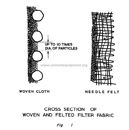
Fibres used in the manufacture of fabrics for filtration are almost exclusively synthetic
and they are either woven or needle felted – see Figure 1. Woven fabrics are smoother
and more easily cleaned than felts and sometimes, at low loads, no cleaning devices are
needed because the fabric is self cleaning. On the other hand they often camot be
cleaned too vigorously because this would break down the entire dust cake and force the
dust between the fibres so that the dust emission would be high. Needle felts are less
permeable than woven fabrics, but they can be operated at considerably higher filtration
velocities. The pores in needle felts are very small compared with woven fabrics, so
dust penetration is low.
Generally, the filter elements, whether of woven or felted fabric, are cylindrical, but
some manufacturers have adopted flat panel, or envelope elements.
3. CLEANING MEITIODS
The removal of the accumulated layer of dust from the filter fabric can be achieved in
many ways including collapse of the filter element, mechanical shaking, reverse air
flow, reverse air pulse and reverse air jet. Any one, or combination of these methods
may be employed but, as a generalisation, the reverse air pulse and reverse air jet are
usually associated only with filters having needle felted elements.
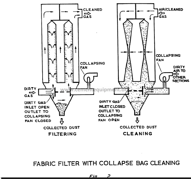
Cleaning by collapse of the fiker element – see Figure 2 is a method used when the
fabric is relatively weak, as is the case with glass fibre, and when cake release is
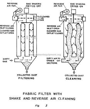
relatively easy. Stronger fabrics and the necessity for a more vigorous action in order
to dislodge the cake leads to shake cleaning, often with the assistance of a reverse air
flow, see Figure 3.
During the collapse of the filter ekment, or the shake or reverse air period, the gas
flow must be stopped in order to allow the dust cake to fall away from the fabric.
Thus, a filter plant must be made up of a sufficient number of separate compartments,
each containing a group of filter elements, to allow one compartment to be taken out
of service at a time for cleaning. If there are only a few compartments in the filter,
then taking one off stream will markedly increase the flow, and consequently the
pressure drop across the others, and this factor must be taken into account at the design
stage.
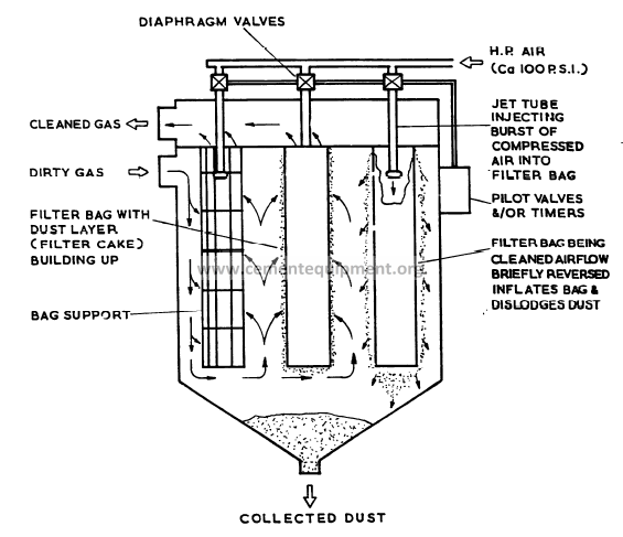
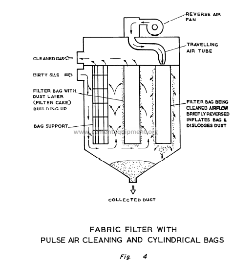
With reverse air pulse cleaning, moderately pressurised air from a secondary blower is
introduced into the element, often by means of a traveling nozzle (refer to Figure 4).
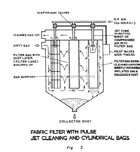
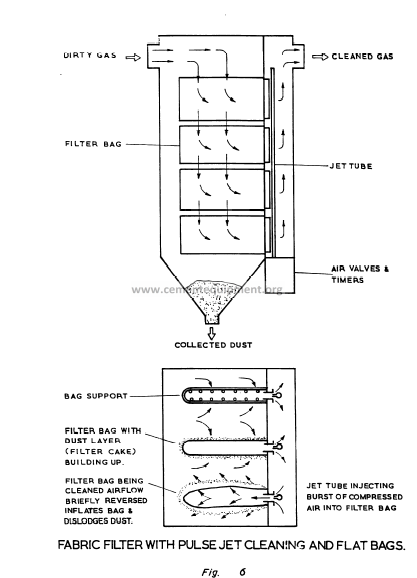
The reverse air jet method utilises a high pressure jet of air which is injected into the
element for a time intwwai of about 0.1 second – see Figures 5 and 6. Cake release is
accomplished by a combination of fabric deformation, due to the shock of air blast, and
flow reversal. Both cleaning methods remove the dust with only a brief interruption in
the gas flow and both invariably use needle felt fabrics.
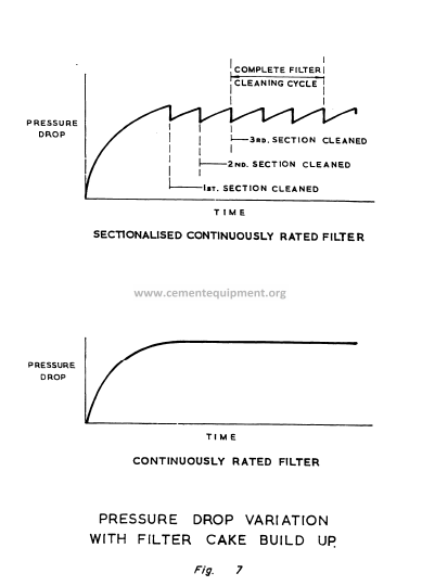
Figure 7 shows the relationship between pressure drop and time both for a sectionalised
continuously rated filter and for a filter of the reverse air puise/jet type.
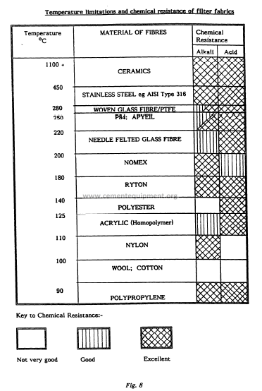
4. TEMPEMTURE LIMITATIONS
Two of the most important factors in determining the life and efficiency of a filter are
the choice of the correct type of f ibre and how it is woven into a fabric. These are
normally chosen according to the type of dust to be filtered and the operating
temperature and nature of the gas being treated. The maximum temperatures at which
various filtration materials can be operated continuously are shown in Figure 8.
Minor temperature excursions above these values may be tolerated, but fabric life would
be reduced. Significant increases in temperature above these levels would result in
damage to the filtration material. In the case of glass f ibre, which is generally silicone
treated, this coating decomposes. Once this has happened the fibres rub against one
another during the cleaning cycle and mechanical failure quickly follows. To limit
operating temperatures to safe values, it is sometimes necessary to provide
automatically controlled fresh air inlets or water spray systems.
Conversely, excessively low temperatures can also influence the life of the fabric, since
such conditions are conducive to condensation of acids or alkalis on the fabric.
Condensation can also cause the dust to adhere so strongly to the fabric that the
cleaning device is unable to remove it. This rapidly leads to complete blinding of the
fabric and the necessity for its replacement.
The chemical resistance of various filtration materials is also shown in Figure 8. The
chemical resistances shown are based on dry gas conditions. When water vapour is
present, degradation of susceptible fabrics will be accelerated.
5. BAG FILTER SIZING
5.1 Filtration Velocity
This is the velocity of the dust and its carrier gas close to the surface of the filter ,
fabric. It is the value of the gas flow rate divided by the area of filter cloth surface ,
through which it passes.
Filtration velocity, or air to cloth ratio, dictates the size of filtration area necessary
for a particular volume flow rate of gas. The type of fabric and its cleaning mechanism
limits the range of filtration velocities that can be achieved by that particular unit.
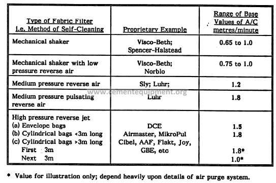
Table 1 gives base values of air to cloth ratios for various types of filter for normal
“ dusts. These values relate to ordinary types of dust in moderate concentrations for
“normaltf application. These values may be increased by Up to 10% when the dust is
known to be easy to filter. An example of this would be clinker dust which is generally
coarsely sized. These values should be reduced by up to 20% for “difficult!? dusts. Fine
dusts such as coal dust, alkali-enriched flue dust and additives such as silica fume are
examples of difficult dusts.
TABLE 1: Base Values of Air to Cloth Ratio for Various Tvtws of Filter Plant
for “Normal” Dusts
5.2 Estimating Dedusting Air Flow Rates
The recommended reference on this subject is “Industrial Ventilation” published by the
American Conference of Government Hygienists. Some guideline values are summarised
below;
Belt conveyor transfers: 323 cfin per foot of belt width for belt speeds
< or = 3.3 ft/sec.
Belt wipers: 215 cfin per foot of belt width.
Vibrating screens: 66 cfrn per square foot of screen area.
6. CHOICE OF CORRECT FABRIC FOR APPLICATION
Table 2 indicates what filtration materials have been found to perform best in different
applications within the cement manufacturing process. The base filtration velocities have also
been indicated for each application. Gore-Tex fabrics and their “lookalikes” appear to be able
to operate at high filtration velocities. However the surfaces of these fabrics are very delicate,
and at high gas velocities may be eroded. The fabric property would then revert to that of the
base fabric, a normal needle felted medium. These fabrics do have excellent dust release
properties and should be used where dust release is a problem.
TABLE 2: The Right Fabric for the Right Dust
(Subject to Temperature Limitations)
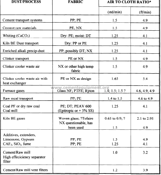
* Air to cloth ratio for DCE type filter. Add up to approximately 20% for pulse jet filters with
cylindrical bags < 3m long (see Table 1).
Key: PP = Polypropylene PE = Polyester DT = Dralon T NX = Nomex
PEAV 600 = special fabric, do not speci@ without finther advice
SS = stainless steel fibre NF = Needle felt
‘7. TROUBLESHOOTING
If a filter is consistently failing for whatever reason it is worthwhile obtaining the
original design data and comparing this with the current operating conditions. Several
modifications may have been carried out over the years on the plant being de-dusted
and these could have drastically changed the filter duty.
Increased emission levels are usually caused by broken filter bags. If the increased
emission level has been indicated by a dust monitor and not visually, it would be
worthwhile first checking the emission visually if this is possible. If this is not possible,
the operation of the dust monitor should then be checked. This may require that a dust
emission test be carried out to check the accuracy of the monitor.
In smaller filters broken bags are usuaily located by checking each individual bag. This
would be a very arduous task however on a larger filter. For filters with long
cylindrical bags suspended from a tubesheet, a broken bag can sometimes be detected
by a pile of dust on top of the tube sheet next to the broken bag. It is therefore
important to clean the tubesheet after each maintenance. For older filters with bags
that are not supported by tubesheets the task can be more arduous. It is possible tO
locate the compartment or compartments that have broken bags by selectively isolating
each compartment in turn and noticing the change in dust emission, especially if a dust
monitor has been installed.
Increased dust emissions can also be caused by leaks in the tubesheet or internal
chambers. Unless the crack or hole is relatively large the locations of these leaks are
not always easy to find. Making use of fluorescent powder and a UV lamp can greatly
assist in locating the leaks. A few kilograms of fluorescent powder are introduced in
to the intake of the filter whilst it is in operation. The filter is then run for a few
minutes to allow the powder to work its way through. The filter is then stopped and
inspected internally with a W lamp.
Increased pressure drop across a filter is usually caused by blinded bags. If the pressure
drop suddenly increases or reduces, a similar change on the exhaust fan current drawn
may also be observed. If this is not observed and the dust emission has not increased,
then the pressure tappings should be checked to see if they are blocked. Blinded bags
usually result from problems with the cleaning mechanism. This could result from a loss
in compressed air pressure for pulse-jet filters. For product collecting filters on
cement milIs it is normal to interiock the compressed air supply line pressure to mill
operation. If the air pressure drops the mill is tripped out. Low air pressure apart from
compressor fauits, can be caused by faulty water traps which have resulted in the line
filters blocking. Excessive oil or water entrained in the air is often the cause of failure
of the air management system and is an indication of faulty compressor operation.
Blinded bags can also result from operating below the dew point of the gas resulting
in condensation on the bags, which can render the bag cleaning device ineffective. Poor
gas distribution through a filter can also be detrimental to its operation with high flow
areas causing re-entrain.ment of the dust and excessive pressure loss across the filter.
Short bag life can be caused by poor gas distribution. Areas with high gas velocities can
result in rapid bag wear due to excessive impingement of dust on the bags. High gas
velocities can cause attrition between individual bags also resulting in wear.
Short bag life can result from incorrect fabric choice for the application; high gas
temperatures and chemical attack are also causes of premature failures.
8. COMMENTS ON APPLICATION
As mentioned above major problems can result if condensation occws leading to blinding
of a fabric. Maintaining gas temperatures below the rating of the filter fabric is also
important to avoid it being overheated. These factors must be borne in mind when
deciding whether or not a fabric filter should be used to de-dust the gases from any
particular process. It is possible, though not necessarily practicable, to alter the
condition of unsuitable gases if the use of a fabric filter is essential.
When the moisture content of the gases is high at relatively IOW temperatures, as is the
case with the exhaust streams from wet and semi-dry process kilns, an electrostatic
precipitator would be the obvious first choice. A fabric filter could be used if
supplementary heaters were installed in order to pre-warm the filter.
In the case of dry process, suspension preheater or precalciner kilns, the waste gases are
naturally dry and at first sight might seem to be suited for a fabric filter. However,
the temperature of these gases is too high for the use of bag fiIters and cooling would
be necessary. This is best carried out by the evaporation of water into the hot gases
in a conditioning tower. The increased moisture content of tie gas makes it more
favorable to use electrostatic precipitation. A further factor to support this arises
when use is made of the waste gases in the milling/drying circuit. Contact with the raw
materials increases its moisture content and reduces the gas temperature.
Electrostatic precipitators are the preferred equipment for dust removal from kiln
waste gases in U.K. and most of Europe. This is not the case in the U.S. A., where
fabric filters on cement kiln exhausts are much more commonplace. The reasons for
this were mainly political when there were serious air quality problems in the Lehigh
Valley region and others. Other possible reasons may be a history in the U.S.A. of badly
designed electrostatic precipitators, which gave rise to the impression that high
efficiency gas cleaning could not be achieved by electrostatic precipitators.
The installation of large fabric filters entail lower capital costs than electrostatic
precipitators (although running costs are higher).
In some cases the chimney, or exhaust stack, can be dispensed with.
The latter point is of particular interest since, for example, in the U.K. the Alkali
Inspectorate demand that the waste gases be exhausted to atmosphere via an exhaust
stack of a defined height. In the U.S.A. louvre openings in the roof of the filter housing
are currently acceptable. It has been suggested that the louvre discharge system
facilitates the location of a faulty bag, whereas when a chimney iS used the task is more
difficult. This is likely to change as new environmental legislation in the U.S.A.
requires exhaust stacks to be installed on existing and new bag filter installations. This
is to enable the whole exhaust stream to be measured.
A large quantity of water is required to cool the gases from a dI’Yprocess kiln (about
200g of water per kg of clinker) and in some parts of the world such quantities are not
available. Electrostatic precipitation can be extremely difficult k these circumstances
(due to high dust resistivity) and a fabric filter then could be considered. Its size
however would be excessive as the gas would be cooled by ambient air and thus result
in an increase in the quantity of gas to be treated. The filter medium, which is
invariably glass fibre for such applications, demands a low fikration velocity for
satisfactory operation – typically 0.5 -0.6 metres per minute and this also dictates a
large sized filter plant.
The waste air stream from a grate type of clinker cooler is very (h’y and the resistivity
of the dusts is generally high. The gas temperature of this stream is typically about
300*C but this can increase to 500°C during a kiln flush. To enable the use of a filter
fitted with Nomex or polyester needle felt bags a method of cooling the gas is required.
Gas was cooled in the past using water sprays but most modern installations incorporate
an air to air heat exchanger. A cold air bleed may also be incorporated in the circuit
for emergency use during a kiln flush. The coarse nature of the dust permits a filtration
velocity of about 1.5 m/min, thus making the filter relatively compact.
Experience with water spray systems on existing clinker cooler applications has not been
encouraging and where fabric filters have been used, temper~ture control by the
automatic introduction of fresh air has been opted for.
Fabric filters and electrostatic precipitators have both been used to de-dust cement mill
exhaust streams for many years. The trend is towards larger closed circuit milling
operations with separate mill and separator ventilation circuits. Fresh feed to the mill
is partially cooled by the coarse returns from the separator. This together with
improved mill ventilation results in less cooling water being required during the milling
process. Hence most recent cement mill installations have opted for bag filters to dedust
the mill and separator circuits instead of precipitators.
The fabric filter finds its greatest application, in the cement manufacturing process,
in the removal of dust from ambient air. Examples of these are at conveyor transfer
points, on rail wagon tipplers, de-dusting loading chutes and venting silos. All these
applications can be successfully de-dusted with correctly sized filters. Problems have
been encountered de-dusting clinker conveyors due to the passage into the filter of
glowing particies, which burn the filter elements. A satisfactory solution would seem
to be the installation of an inertial collector before the
glowing particles before they enter the filter. Ceramic
for this application.
filter in order to remove the
fibre filters are to be tested
9. RECENT DEVELOPMENTS
DCE Ltd and Neu Engineering Limited manufacture a rigid self-supporting element
which can also be retrofitted to an existing Dalamatic type filter or installed in new
filters. An element and the way it is installed in a filter is shown in Figure 9. These
elements are moulded from sintered plastic granules and have a profiled outer surface
which is treated with a permeable coating of PTFE.
The duty of each module is greater than a similar sized fabric filter due to the
increased surface area developed by the profiling. The base filtration velocity for these
elements still remains at 1.5 m/min.
At present the filter medium is limited to a maximum operating temperature of 60°C.
The manufacturers are currentiy looking at methods of raising this operating
temperature.
There is a growing number of areas where sintered ceramic fibre filter elements may
have applications within the cement indus~. These filter elements are suited to very
high temperature applications and therefore do not require protection in the same way
as a bag filter. Their disadvantages are primarily the high cost of the individual
elements, the relatively small dimensions of the individual filter elements and the high
cost of the resulting filter unit. Further developments in this area may change the
economic viability of this type of filter for high temperature applications.
Appendmi
3. Hood Design
Once the processes of identification and
quantification have been carried out dust
control engineer may plan his campaign both
from the engineering and economic viewpoint
Rarely can a particdar dust source be
completely eliminated, although the dust
control engineer and the process engineer
should consider whetherany change of
production technique can minim- if not
eliminate, the problem. The reduction of a
particular emission source by either
suppression or containment is, in practice,
often possible and usually repays investigation.
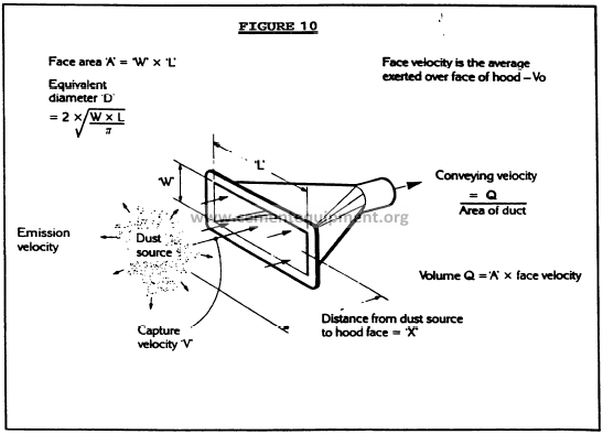
The next step is to design the exhaust
enclosure. Formulae for hood design do exis4
although experience counts for a great deal in
their application. The starting point for a hood
design calculation is determining the emission
rate or velocity of the liberated d- From this
a capture velocity maybe decided upon which
willalso be influenced by the type of dust
FinaIfythe siting of the capture ~ from