Innovations In Cement Manufacturing: Complete Guide & Downlo
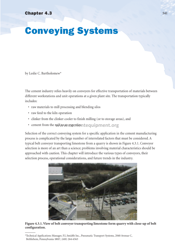
The cement industry relies heavily on conveyors for effective transportation of materials between different workstations and unit operations at a given plant site, and Chapter 4.3 of the Innovations in Cement Manufacturing series makes the point that this transportation is anything but trivial: the typical plant moves millions of tonnes per year of limestone, clay, additives, coal, raw meal, clinker, gypsum, and finished cement between crushers, mills, storage silos, the kiln system, and dispatch, and every tonne moved costs money in power, wear, maintenance, and spillage. The transportation typically includes raw materials to the mill processing and blending silos, raw feed to the kiln operation, clinker from the clinker cooler to finish milling or to storage areas, and cement from the mill to storage silos, and the selection of the correct conveying system for each of these movements is complicated by the large number of interrelated factors that must be considered. This article expands the original chapter into a complete technical package covering the conveying technologies in service in cement plants, the selection criteria that govern their choice, the design and operating principles of each major conveyor family, the innovations that have improved reliability and energy use, and the engineering practice that keeps a conveying system operating at design duty.
The purpose of this article is to give the plant engineer and the project designer a working command of materials handling for cement manufacture: the properties of the materials to be conveyed and how they dictate the machine choice, the belt conveyor as the workhorse of the plant, the bucket elevator, the screw conveyor, the air slide, the drag chain conveyor, and the pneumatic systems, the design of transfer points and dust control, and the maintenance and safety practice without which no conveying system survives for long in cement service.
1. The Conveying Task in the Cement Plant
A modern dry-process cement plant is a materials handling machine wrapped around a chemical reactor, and the figures prove it. For every tonne of clinker produced, the plant moves roughly 1.6 to 1.7 tonnes of raw materials and additives to the raw mill, around 1.1 tonnes of raw meal to the kiln system, the entire cooled clinker output plus returned dust to the finish mills, and 1 to 1.5 tonnes of cement to storage and dispatch. On a 5,000-tonne-per-day plant that sums to more than 25,000 tonnes of material movement per day, and each movement is a decision about equipment, energy, and maintenance.
The conveying systems form the skeleton of the plant layout. The quarry material arrives at the crusher, is conveyed to the prehomogenization piles and the raw material storage, is fed to the raw mill, and the raw meal is moved to the homogenizing silos; the kiln feed is then conveyed to the preheater top, and the clinker travels from the cooler through the clinker storage to the finish mills; the finished cement moves to the cement silos and then to the packing plant, the bulk loading station, or the rail and ship terminals. Each of these links has its own service conditions, its own tonnage, and its own material properties, and no single conveyor type serves all of them well.
The selection problem is made harder by the range of materials the conveyors must handle. Limestone and clinker are abrasive, hot, and lumpy; raw coal is dusty and combustible; raw meal and cement are fine powders that fluidize and dust explosively if handled carelessly; gypsum and additives come in lumps of varying moisture. The conveyors must also operate in all weather, at temperatures from freezing to the 300 to 400°C of hot clinker at the cooler discharge, with dust collection at every transfer, and with the reliability demanded by a process that cannot easily be interrupted.
The chapters of this series that describe the unit operations all assume that the materials arrive and leave continuously and at design rates. The conveying systems are the element that makes that assumption true, which is why their design, selection, and maintenance receive a full chapter of the Innovations series and why the discipline of materials handling engineering is one of the most commercially valuable skills in the cement industry.
2. Material Properties and Their Influence on Conveyor Selection
The first step in selecting any conveyor is a precise statement of the material properties, and the original chapter insists on this discipline because the property list decides the machine family. The critical properties for cement service are the bulk density, the lump size and the percentage of lumps, the angle of repose and the surcharge angle, the moisture content, the abrasiveness, the temperature, the dustiness, and the flow characteristics of the material when stored or aerated.
The bulk density determines the volumetric loading of the conveyor and therefore its size and speed. Raw limestone may lie at 1.4 to 1.6 t/m3, crushed coal at 0.7 to 0.9 t/m3, raw meal at 1.0 to 1.2 t/m3 in the loose state, and cement at 1.1 to 1.5 t/m3 depending on aeration and compaction. The lump size sets the minimum belt width for belt conveyors and the size of bucket elevators and chutes; the rule of thumb is that the belt width should be at least three times the largest lump for mixed material. The moisture content affects the belt angle, the likelihood of sticking and build-up, and the need for drying or dust suppression.
Abrasiveness determines the wear life of every component in contact with the material. Clinker is among the most abrasive materials conveyed in industry, and its conveying dictates hard-faced chutes, ceramic-lined transfer points, and a rotation schedule for buckets and drag links. Temperature is equally decisive: hot clinker can be conveyed on pans and drag chains designed for 400°C, but cannot be put on a rubber belt until it has cooled below about 100°C, and cement from the mill, at 90 to 120°C, damages conveyor belting unless the belt is selected for heat resistance.
Dustiness and flowability complete the picture. Raw meal and cement are fine powders that behave as liquids when aerated, which makes air slides and pneumatic systems natural choices for their transport, while at the same time making them the dust control challenge of the plant. The engineer therefore builds the selection from a matrix of these properties against the route: a short horizontal or inclined run of fine powder at high tonnage will be an air slide or a drag chain; a long inclined or level run of lumpy material will be a belt conveyor; a steep vertical lift will be a bucket elevator; and a long route through a congested area at moderate tonnage will often be a pneumatic or drag chain system.
3. Belt Conveyors: The Workhorse of Materials Handling
The belt conveyor is the dominant machine of the cement plant, handling the quarry-crusher links, the long runs to the raw mill feed, the clinker transport where temperatures permit, and many of the additive and gypsum routes. Its advantages are the classic ones: continuous operation at any tonnage, low energy per tonne, negligible degradation of the material, and a construction that is simple enough to be maintained by plant personnel.
The anatomy of a belt conveyor is standardized. The belt itself, a carcass of woven fabric or steel cords protected by rubber covers, runs over a head pulley at the discharge and a tail pulley at the loading point, supported along its loaded length by troughing idlers that cup the belt into a shallow trough, with return idlers supporting the empty belt underneath. The drive is applied through the head pulley by one or more drive units, and the belt tension is maintained by a take-up, either a screw take-up at short centres or a gravity take-up tower on the long conveyors. The conveyor is carried on a steel structure, and the length can extend for kilometres on the quarry link or for less than a hundred metres inside the plant.
The design of a belt conveyor is a mechanical engineering exercise in tension and power. The effective power is computed from the sum of the belt friction, the idler rolling resistance, the material lift, the acceleration and deceleration of the material, and the accessory losses of the skirt boards and scrapers, and the belt tension at every point along the route is calculated to size the carcass, the number of plies or the cord diameter, and the drive. The maximum tension occurs around the drive pulley, and the design must respect the belt’s rated working tension and the pulley wrap angle, adjusted by snub pulleys or a take-up location, to avoid slip.
The choice between fabric and steel-cord belting is governed by the length and the tension: fabric belts, with working tensions up to around 1,000 N per millimetre of width, serve the short and medium conveyors of the plant, while steel-cord belts, rated up to 6,000 N/mm and more, are used on the long quarry conveyors and the high-lift incline conveyors where a single belt must carry great tension without excessive elongation. The belt speed is chosen between roughly 1.5 and 4.5 m/s, higher speeds favouring economy on long straight runs, lower speeds favouring cleanliness and gentle handling at loading points and inside buildings.
The innovations in belt conveying are numerous and continuous. The long-distance conveying achieved by modern steel-cord installations, sometimes replacing truck haulage from the quarry at a fraction of the energy and emissions, is one of the great logistics innovations of the industry. The curve-trough belt conveyor, which turns horizontally through a designed radius without a transfer station, has eliminated transfer points on long quarry routes; the pipe conveyor, in which the belt is wrapped into a tube by special idlers, carries dusty and spillage-prone materials through built-up areas without dust release; and the vertical and high-angle variants, using cleats, pockets, or sandwich belts, lift material at angles up to 90 degrees where space is scarce.
4. Designing the Loading Point: Feeding, Skirts, and Scrapers
The belt conveyor is only as good as its loading and transfer points, and the belt conveyor failures of cement plants concentrate overwhelmingly at the loading points. The material must be loaded onto the belt at a velocity close to the belt speed, centred on the belt, and at a controlled rate, and the transition from the chute to the belt is made with a skirt board assembly: vertical steel or rubber side plates, suspended from the structure about 5 to 8 millimetres above the belt, forming a short hopper that contains the material until the belt has accelerated it.
Skirt friction is a substantial fraction of the conveyor power on short belts, and the modern practice is to make the skirt length as short as practical and to fit the skirts with flexible rubber sealing strips that ride on the belt. The load zone is supported by impact idlers, or better, by resilient impact beds of rubber-cushioned bars, to absorb the kinetic energy of the falling material. The modern impact bed is one of those quiet innovations that transformed conveyor reliability: the old three-roller impact idlers were cut by the impact and by the abrasive material, while the bar bed spreads the load over a full cushion.
The discharge end carries the first of the belt cleaning systems. The material sticks to the belt as it passes over the head pulley, particularly when damp or sticky, and the return strand then deposits it along the whole underside of the conveyor unless the belt is cleaned. The standard train is a primary scraper at the head pulley, a secondary scraper behind it on the return run, and often a V-plough ahead of the tail pulley to sweep the return belt. The innovation trend is toward polyurethane and tungsten-carbide tipped scrapers with automatic tensioning, because a well-tensioned scraper removes the carry-back at the source, while a badly maintained scraper spreads the problem over the entire structure.
Water and dust management completes the transfer point design. The loading point of a dusty material is always fitted with a dust collection hood connected to the plant dedusting network, and the transfer chutes are designed with steep angles and smooth liners, often ceramic, to keep abrasive material moving and to prevent the build-up that collapses in slides at the most inconvenient moments. The modern transfer chute is designed with the material trajectory in mind, using the discharge trajectory calculation so that the material lands on the receiving belt at its speed and at its centreline, the single most effective measure in reducing belt damage and spillage.
5. Bucket Elevators: The Vertical Lift
Where material must be lifted vertically, and the plant layout cannot make room for an inclined conveyor, the bucket elevator is the standard machine. The bucket elevator consists of an endless chain or belt looped over a head and a tail wheel, carrying a series of steel or plastic buckets that dig the material at the bottom boot and discharge it over the head wheel, either by centrifugal throw or by gravity over a discharge lip.
Two discharge principles distinguish the families. In the centrifugal type, the buckets run fast enough for the material to be thrown clear of the wheel by centrifugal force into the discharge chute; this is the common pattern for free-flowing, granular, and lumpy material, and the fast chain speed and the digging action at the boot define its operation. In the continuous type, the buckets run slowly and are spaced so closely that they discharge over each other’s back lip by gravity, making it the right choice for fine, dusty, or sticky material, and for gentle handling of fragile material.
The bucket elevator is the natural partner of the belt conveyor in the vertical sections of the plant: raw mill reject and kiln feed circuits, fuel feeding, and the return of separator tailings all use elevators where the headroom permits. The elevator is a demanding machine to maintain because every bucket passes through the digging zone twice per revolution, and the duty is abrasive. The modern trend is toward belt-mounted buckets instead of chain, because the rubber belt is lighter, quieter, and vibrates less, and toward elevator boots with automatic tensioning and spring-loaded lower bearings that protect the machine from the inevitable occasional overload.
Safety and cleanliness are the elevator’s weak points. The interior of the casing is a dusty, confined space where material builds on the bucket backs and the casing walls, and the explosion risk with coal dust dictates flameproofed drives and explosion relief panels on coal elevators. The modern elevator is supplied with a clean-out door at every level, a casing designed for inspection, and level and speed sensors on the head shaft whose trip activates the feed interlock before spillage occurs.
6. Screw Conveyors: Short, Enclosed, and Simple
The screw conveyor, an Archimedean screw rotating inside a closed trough, is the plant’s universal short-distance solution: feeding additives and gypsum to the mill inlet, conveying collected dust from hoppers, distributing material into bin inlets, and serving the many short horizontal and inclined runs below the process equipment. Its virtues are compactness, total enclosure of the material, and mechanical simplicity; its vices are high friction losses, high screw and trough wear in abrasive service, and a general unsuitability for long distances and high capacities.
The capacity of a screw conveyor is set by the screw diameter, the pitch, the speed, and the trough filling, which for cement materials is typically limited to 30 to 45% of the trough volume to avoid flooding and degradation. The power is dominated by the bearing friction and by the material friction against trough and screw, so the specific energy is several times that of a belt conveyor, and the wear rate in abrasive clinker or limestone service is severe enough that the flights are hard-faced and the trough lined, and the screw is treated as a consumable.
The screw conveyor’s maintenance burden is a function of its bearings. The intermediate hanger bearings, which support the screw between the end bearings, run submerged in the material, and their failure is the classic screw conveyor failure mode; the modern trend is toward self-lubricating and sealed hanger bearings, and toward screw lengths short enough to keep the number of intermediate bearings to a minimum. The end bearing at the discharge is the other critical point, loaded by the axial thrust of the screw, which is carried by a thrust bearing at the drive end.
For all its limitations, the screw conveyor remains irreplaceable in the compact spaces of the cement plant, and the innovations around it have been materials and drive innovations rather than conceptual ones: hard-facing alloys and ceramic liners that multiply service life, shaftless screws for sticky materials where a central shaft cannot be tolerated, and the screw feeder, which is engineered as a metering device at the bottom of bins and silos, where its short pitch at the inlet and its speed control provide the regulated feed that the process demands.
7. Air Slides: Conveying Powder on a Bed of Air
The air slide is one of the most elegant machines in cement service, and the industry could scarcely function without it. The air slide is a rectangular duct, inclined at 4 to 8 degrees, divided horizontally by a porous fabric: the lower compartment receives low-pressure air at 0.5 to 2 kPa, which passes through the fabric and aerates the powder in the upper compartment; the aerated powder fluidizes, its effective friction falls to nearly nothing, and it flows downhill along the slide like a viscous liquid, at velocities of the order of 0.3 to 1 m/s and at any required capacity.
The air slide serves the fine powders, raw meal and cement, exactly where they dominate: under the mill discharge, below the separators and the dust collectors, feeding the silos and the kiln system, and above all in the kiln feed circuits where the raw meal must be moved gently and reliably around the preheater tower. The slide consumes only the air it pushes, typically 1 to 2 m3 of air per minute per square metre of slide area, and the power cost is low, and it has no moving parts except the blower, which is why its reliability record is the best in the business.
The fabric is the slide’s life element. The porous media, woven polyester, nylon, or porous ceramic tiles in the hottest services, must be robust to the moist, abrasive powder, and must never blind; a damp powder or a condensation event blinds the fabric and the slide silently stops flowing. The design rules for a reliable slide include generous aeration, a fabric area based on the tonnage and the slope, inspection hatches at intervals, and an air supply that is filtered, dried, and free of oil, because oil contamination of the fabric is nearly impossible to cure.
The air slide family extends to the Airslide-equipped silo extractors and the aeration systems of the storage silos themselves, discussed in the chapters on storage. The innovation record of the slide is a reminder that some of the most important conveying inventions are the quiet ones: a duct, a fabric, and a fan, arranged to exploit the fluidization that the powder itself provides, with a maintenance cost near zero and a service life measured in decades.
8. Drag Chain and En-Masse Conveyors
The drag chain conveyor, and its high-capacity relative the en-masse conveyor, fills the gap between the belt conveyor and the air slide. The en-masse conveyor is a closed rectangular casing in which a chain, carrying flights at intervals, travels through the full width of the casing; the material fills the cross-section and is moved as a slowly rolling plug by the friction of the flights and the chain. The casing is totally enclosed, the conveyor can run horizontally, at slopes, and vertically in one continuous path, and it handles fine, granular, and lumpy materials alike.
The en-masse conveyor’s niche in cement service is the multi-stage route: raw meal distribution to the kiln silos, cement distribution to the silos and dispatch, clinker transport from the cooler to storage where temperature is too high for a belt, and the return of baghouse dust. A single en-masse conveyor replaces a series of belts and elevators with one machine and one drive, at an energy consumption that, being proportional to the material column friction, is higher than a belt but much lower than pneumatic conveying, and with the total enclosure that the dusty materials demand.
The drag chain’s wear points define its maintenance: the chain pins and bushings, the flights, and the casing bottom, which wears wherever the material slides. The chain life in abrasive services is measured in thousands of hours, and the modern practice is a scheduled chain inspection and a planned chain replacement against the wear-out pattern, rather than a run-to-failure policy, because a chain failure empties the whole casing practically overnight. The drive must also be protected: the chain tension is taken by the tail sprocket or a spring take-up, and the drive is fitted with a torque limiter against the jam, because a plugged en-masse conveyor can break its chain outright.
The innovations in this family have been the materials of the wearing components, quenched and tempered alloy chain and hardened flights, the growth of plastic and composite flights for light duties, and the drive packages with soft starts and load monitoring that extend chain life. The popularity of the en-masse conveyor has risen steadily with the industry’s preference for enclosed, dust-free transport, and its place in the modern plant, next to the belt for the long hauls and the air slide for the powders, is secure.
9. Pneumatic Conveying: Powder in the Pipe
Where a fine powder must travel a long route through congested equipment, or climb steeply, or reach a distant silo some hundreds of metres away, pneumatic conveying moves it as a suspension in air. The cement industry uses pneumatic systems for raw meal transfers, for cement wherever its layout demands, and crucially for the kiln bypass dust and the collected dusts whose conveyors would otherwise lose them. The modern dense-phase pneumatic systems convey at low velocity, with the material moving as plugs and dunes, at very low air consumption, and with correspondingly low power and low wear.
The systems divide by phase and pressure. The dilute phase system carries the material suspended in a high-velocity air stream, 20 to 30 m/s, at high air volume and high power; it is simple and flexible but abrasive and energy-hungry. The dense phase system pushes the material along the pipe at 0.5 to 5 m/s in plugs, using a pressure vessel or a screw pump at the feed end, and its abbreviation of energy and wear made it the standard for the long cement and raw meal routes. The pressure side of the families runs from the positive-pressure systems, in which the blower or compressor pushes, to the negative systems, in which a vacuum pump at the discharge draws, the latter being the natural choice where the material must be picked up from several points, such as the vents under dust collectors.
The physics of dense-phase flow is the physics of the plug: the air pressure builds behind each plug until it yields, the plug slides and breaks, and the cycle repeats, which gives the familiar surging flow and the requirement for care in pipe sizing, bend radius, and receiver design. The wear concentrates in the bends, where the particles change direction at high velocity, and the innovation record of pneumatic conveying is dominated by the bend: the long-radius bend, the ceramic-lined bend, the double-wall bend, and the pocket bend with an internal air pocket that shields the wall, each progressively reducing the wear that once wore a pipe out in months.
The pneumatic system demands a filtration discipline: the conveying air is never clean, and the receiver at the destination must separate the material from the air through a bag filter or cyclone, whose clean air exhaust and dust return are themselves a mini-conveying problem. The power consumption of pneumatic conveying remains the highest per tonne of the enclosed systems, which is why the modern plant reserves it for the routes where no other machine fits, and why the energy-conscious designer double-checks every pneumatic route against an en-masse conveyor or an air slide before committing to the air.
10. Heavy-Duty Handling of Hot Clinker
The clinker transfer from the cooler discharge to the clinker storage or the finish mills is the toughest conveying duty in the plant, and it deserves its own treatment. The clinker leaves the modern cooler at 70 to 150°C in a well-run line, but older coolers and upset conditions can present material at 300°C and above, and the clinker is angular, abrasive, and contains occasional red-hot cores. Rubber belting cannot touch this service, and the industry’s answer is the family of heavy-duty machines: the drag chain clinker conveyor, the pan conveyor, and the bucket elevator where vertical lift is required.
The pan conveyor carries the hot clinker on overlapping steel pans, mounted on a robust chain, through the cooler discharge tunnel to the clinker silo or the finish mill building, at any required capacity, with a design that tolerates the heat, the abrasion, and the occasional flake of red-hot material. The drag chain clinker conveyor performs the same duty in a fully enclosed casing, which additionally controls the heat and dust radiated into the plant. The wear picture is the heaviest in the plant: pan and chain consumptions are measured in months, and the maintenance forecasts of the clinker conveying system are a permanent line in the plant’s budget.
The design of the clinker conveyor route is a study in protecting the rest of the plant. The conveyor is installed with expansion joints between its sections, because the cooler discharge structure moves with its own thermal cycles; the hot material is quenched or air-cooled on the conveyor where necessary; and the drive is oversized for the worst-case filling because the clinker flow from a cooler is anything but uniform. The discharge to the clinker storage is fitted with a skilled arrangement of chutes and gates, so that the hot material can be directed between the silo intake, the stockpile stacker, and the direct route to the finish mill feed without a stoppage of the line.
The modernization of clinker handling has reduced the heat released to the plant environment: the modern enclosed conveyor, the insulated transfer points, and the improved cooler performance, which delivers the clinker colder in the first place, have together cut the thermal damage to structures and belts and improved the working conditions of the plant staff. The clinker conveyor remains what it always was, the machine that must never fail when the kiln is running, and its redundancy, one machine in operation and one in reserve on the big lines, is standard practice.
11. Transfer Points, Chutes, and Dust Control
Every conveyor hands its material to the next device through a transfer point, and the transfer points are where spillage, dust, build-up, and degradation are born. The modern design discipline treats the transfer point as a system: the discharge trajectory of the incoming conveyor is calculated precisely, the chute is designed so the material stream passes through its centerline, the receiving belt is loaded centered and at matching velocity, and the whole assembly is enclosed and connected to the dust collection network.
The chute design deserves the engineer’s attention because it concentrates all the material’s properties. The chute walls must be steep enough to keep the material moving under its own angle of repose for the specific material, the liners must survive the abradability, and the chute must not create velocity changes that throw dust out of the stream. The modern chutes use ceramic-lined straight sections, radiused bottom curves, and flow-smoothing internal geometry, and the performance of these chutes is such that a well-designed transfer point runs for years without a scrape, while a poorly designed one demands a full-time attendant.
Dust control at the transfer points is a hierarchy, not a single device. The first line is the capture design: the enclosure and the extraction hood are sized from the air displaced by the falling material, which is computed from the material flow and the fall height, and the hood extracts at a rate that creates a slight negative pressure without stealing the material from the receiving belt. The second line is the bag filter or the connection to the plant’s dedusting network; the third is the suppression, water or foam spraying at the chute for the materials that tolerate it, and the fourth, for the priority found in walkways and near equipment, is the mechanical cleaning that prevents the build-up before it becomes a release.
The dust problem at transfer points is aggravated by the aspiration of air into falling streams of powder, the familiar puffs of dust that accompany every free-falling flow of raw meal or cement. The solution of the modern plant is the combination of enclosed transfer chutes, controlled aspiration, and short free falls, with the vertical legs of the plant fabricating the chutes so that the material falls in a contained stream. The result is a plant where, in the words of one commissioning manager, the only dust in the air is the dust that has not yet decided where it is going.
12. Conveyor Selection Matrix
The following table consolidates the selection logic of the chapter into the matrix the project engineer uses, matching the common cement materials and routes against the conveyor families that serve them well:
| Material / route | Belt | Bucket elevator | Screw | Air slide | En-masse / drag | Pneumatic |
| Limestone, quarry to mill | preferred | short vertical | short feed | no | possible | no |
| Raw meal, mill to kiln | dusty | common | short | preferred | common | long routes |
| Coal, storage to mill | preferred | flameproof | feed duty | no | possible | dense phase |
| Hot clinker, cooler to mill | no (hot) | heavy duty | no | no | preferred | no |
| Cool clinker, storage | preferred | common | no | no | common | no |
| Cement, mill to silo | dusty | common | short | very common | preferred | common |
| Collected dust returns | no | possible | common | common | common | preferred |
The matrix is read with the property list of Section 2 in mind: temperature rules out the belt for hot clinker, dustiness favours the enclosed machines for the powders, the lumps rule out the air slide, and the distance and the elevation decide between the belt and the elevator. Where two machines appear equal in the matrix, the tie-breakers are the energy per tonne, the maintenance burden, the space available, and the plant’s existing spare-parts base, and it is the last of these, the parts and skills already in the plant, that frequently settles the final choice.
13. Maintenance, Reliability, and Safety
The conveying systems of a cement plant are maintained on schedules, and the discipline of the schedule is the discipline of the plant’s availability. The modern maintenance planning runs on the classic pillars: the routine lubrication and inspection of drives, bearings, and take-ups; the condition monitoring of the critical items, vibration on the drives, temperature on the bearings, and wear measurement on the chain and buckets; and the planned replacement of the consumables, belt, buckets, flights, and liners, against their expected life curves.
The reliability engineering of conveying has advanced with two instruments. The first is the continuous monitoring of the conveyor parameters: amperage and power draw, belt speed, misalignment switches, belt-slip detection, and the plug-level switches at transfer points, all wired into the control system so that the first sign of trouble trips the feed rather than the conveyor. The second is the structural inspection programme: the welds of the supports, the condition of the belt splices, the wear of the idler rollers, and the alignment of the whole line, checked on a rotating schedule because a failed idler ruins a belt within hours.
Safety is the third pillar, and conveying has its own safety culture. The belt conveyor is guarded along its full length, the nip points at the pulleys are the most dangerous places in the plant, emergency pull-cords run the entire length of every belt, and the confined-space entry to elevator casings and transfer chutes follows the plant’s permit system. The fixed guard and the interlocked access gate are non-negotiable items of the modern installation, and the industry’s accident statistics show that the conveying systems, precisely because they look benign, deserve the strictest discipline of all.
The energy dimension of the maintenance schedule is not to be forgotten: the conveyors of a typical plant draw a significant share of the site’s electrical load, and the energy-saving levers, the variable speed drives on the long quarry belts, the correct idler spacing and alignment that cut friction, the belt-cleaning programme that prevents the carry-back build-up, and the simple discipline of switching empty conveyors off when they are empty, are all maintenance-adjacent practices that the modern energy manager audits alongside the kiln and the mills.
14. Innovations in Conveying: The Modern Frontier
The conveying systems of the cement industry have absorbed every wave of industrial innovation. The electrical drive has evolved from the fixed-speed motor with mechanical couplings to the variable frequency drive with its soft start, its load-proportional speed, and its torque-limited ramp, and the long belt conveyors of the modern quarry are started and stopped by the control system with an assurance that was unthinkable forty years ago. The steel-cord belt and the splice technology have pushed the single-flight length of a quarry conveyor to ten kilometres and beyond, crossing the economic border against truck haulage in most installations.
The measurement and automation of conveying has matured alongside the process control systems described in the later chapters of this series. The belt scale weighs the material in motion with an accuracy that supports the plant’s mass balances, the solids flow meters and the weigh feeders meter the additives and the kiln feed, and the level sensors in the silos and the hoppers are the inputs of the feed control loops, so that the conveying system, traditionally a mechanical service, has become a measured and controlled part of the process.
The newest frontier is the digital one. The conveyor condition monitoring now streams vibration, temperature, and load data to the plant’s analytics platform, where the failure patterns are recognized before they interrupt the line; the motor current signatures are analyzed for belt damage; and the maintenance scheduling is moving from the fixed calendar to the condition-based forecast. The long-term trends point to conveyors that schedule their own inspections and the quarries whose fleets are replaced by continuous haulage, both of which the industry is already demonstrating at commercial scale.
Through all the innovations, the selection discipline of the original chapter remains the foundation: the material properties, the route, the tonnage, and the economics still decide the machine, and the engineer who masters the properties and the physics of each family, the belt’s tension, the elevator’s discharge, the slide’s fluidization, the plug’s yield, can design a conveying system that runs for decades at the tonnage the process demands, with the reliability that keeps the kiln fed and the silos full.
Frequently Asked Questions
What determines whether a material should be conveyed by belt, air slide, or pneumatic system?
Three properties dominate: temperature, lump size, and dustiness. Hot clinker cannot ride a rubber belt and goes to pans or drag chains; lumpy materials rule out air slides and are moved by belts and elevators; fine powders like raw meal and cement fluidize, which makes air slides the cheapest reliable choice for short routes and en-masse or dense-phase pneumatic conveying the choices for long and steep routes.
Why is an air slide so efficient for cement powder?
Because the porous fabric beneath the powder admits low-pressure air that reduces the material’s internal friction to near zero, so the aerated powder flows downhill by gravity at 4 to 8 degrees of slope. The only moving part is the blower, the power consumption is far below any mechanical conveyor, and the reliability record is excellent, provided the fabric is protected from moisture and oil and the air is clean.
Why can’t hot clinker be conveyed on a standard belt conveyor?
Rubber belting cannot survive sustained contact with material above roughly 100°C: the cover hardens, cracks, and delaminates, and a red-hot clinker particle burns through to the carcass. Clinker is therefore conveyed on steel pans or in enclosed drag chain conveyors designed for the heat, and it is only after cooling, in the clinker storage and later handling, that conventional belts return to service.
What is the difference between dilute-phase and dense-phase pneumatic conveying?
In dilute phase the powder is fully suspended in a high-velocity air stream, 20 to 30 m/s, with high air consumption and high power and wear. In dense phase the powder moves as slow-moving slugs or dunes pushed along the pipe at a few metres per second, with a fraction of the air volume and energy. Dense phase is the modern standard for long cement and raw meal routes, while dilute phase survives where short flexible runs justify its simplicity.
Why do transfer points need so much engineering attention?
Because every transfer point is where the material changes direction and speed, and that is where spillage, dust, belt damage, and build-up originate. A transfer point designed with the material’s discharge trajectory, a chute that keeps the stream centered, a skirt system that contains the load, and a dust hood connected to the dedusting network will run clean for years, while a poorly designed point generates spillage and dust problems at every scale from the local walkway to the entire plant.
What does an en-masse conveyor do that the alternatives cannot?
It moves material along an arbitrary route, horizontal, inclined, and vertical, inside one totally enclosed casing and with one drive, replacing a chain of belts and elevators. The enclosure contains the dust, the single machine simplifies the maintenance and the spare parts, and on routes like cement distribution to the silos it combines the cleanliness of the enclosed machines with capacities that air slides cannot reach on their own.
Final Summary
Chapter 4.3 of Innovations in Cement Manufacturing treats conveying as the material backbone of the cement plant, and this article has expanded that treatment into a complete technical package. The article established the scale of the conveying task, the material properties that govern every machine choice, and the selection logic that matches the machine family to the route, and it then developed each major conveyor type in engineering depth: the belt conveyor and its loading points, the bucket elevator, the screw conveyor, the air slide, the drag chain and en-masse machines, and the pneumatic systems.
The operational core covered the especially demanding services, hot clinker handling and the transfer points with their dust control, and it quantified the choice through a selection matrix that the project engineer can use directly. The maintenance, reliability, and safety practice of conveying was treated as the discipline that keeps the skeleton of the plant alive, and the article closed with the innovations, mechanical and digital, that are extending the capability of the belt conveyor, the elevator, and the enclosed machines.
The conclusion of the chapter is that conveying in the cement plant, apparently the most mundane of the unit operations, is in fact one of the most consequential: it is the largest consumer of electrical energy after grinding, the largest source of chronic maintenance cost, and the first place where plant cleanliness and safety are won or lost. The engineer who treats conveying with the same respect as the kiln and the mills, who selects on properties, designs on physics, and maintains on schedule, secures the availability, the energy bill, and the working environment of the whole plant at once.
Get this cement file + the full 931-file package
$249.99 — one-time purchase, instant download, lifetime access
This file is part of the Complete Cement Technical Package (931 files) available from cementequipment.org. Respective rights holders; library copy for the licensed single user.