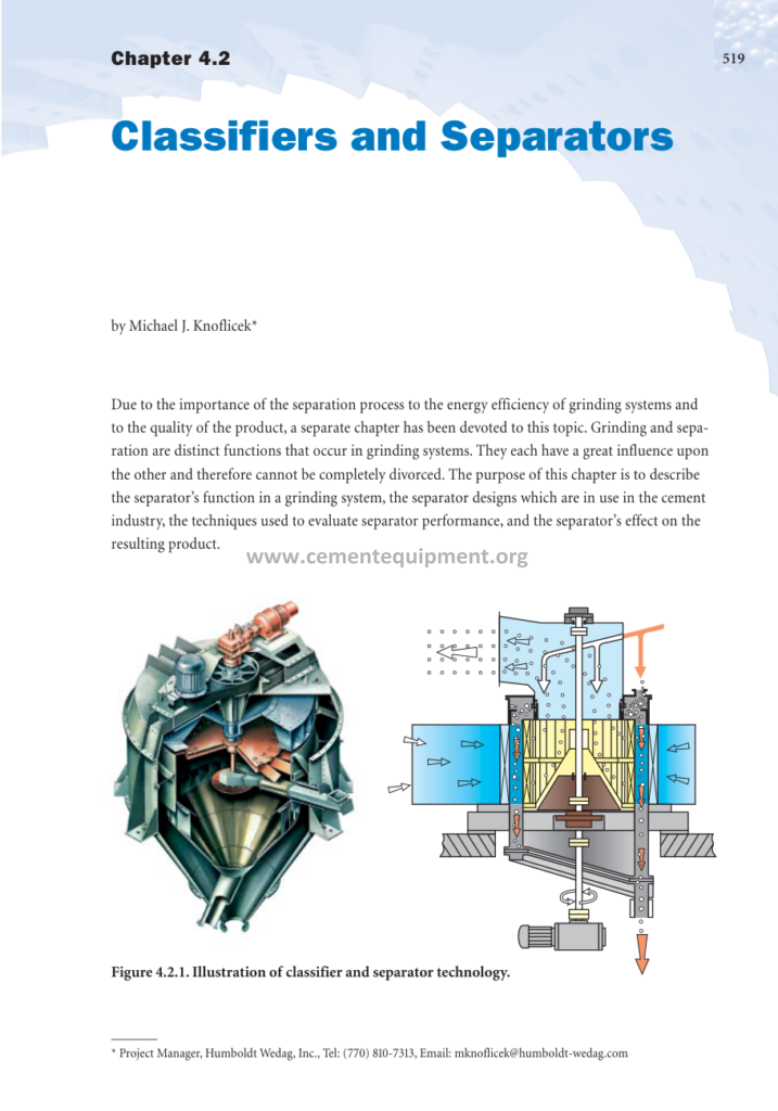
Innovations In Cement Manufacturing: Complete Guide & Downlo
Chapter 4.2 of the Innovations in Cement Manufacturing series, devoted entirely to the separator, opens with a statement that plant engineers intuitively understand but rarely state explicitly: grinding and separation are distinct functions that occur together inside every closed grinding circuit, each influencing the other so strongly that neither can be properly designed, operated, or optimized in isolation. The separator decides which particles may leave the circuit as finished product and which must return to the mill, and in doing so it sets the mill load, the energy efficiency of the comminution process, the particle size distribution of the product, and ultimately the strength development and market performance of the cement itself. This article expands the original chapter into a complete technical package covering the separator’s function in the grinding system, the evolution of separator designs from static cones to modern cage-rotor classifier systems, the analytical techniques used to measure separator performance in the plant, and the practical effect of the separator on the resulting product and on the energy economy of the entire grinding department.
The purpose of this article is to describe the separator’s function in a grinding system, the separator designs which are in use in the cement industry, the techniques used to evaluate separator performance, and the separator’s effect on the resulting product, exactly as the original chapter intends. Along the way the article explains why the third-generation high-efficiency separator became the standard for every modern cement grinding plant, how the cage rotor and vane geometry create the selectivities that produce a steep particle size distribution, and how the operating engineer reads the Tromp curve the way the kiln operator reads the temperature profile.
1. The Role of the Separator in the Grinding System
The grinding task in a cement plant is not, as the casual observer might suppose, a single pass through a mill. Grinding to the fineness required for good cement strength development, with a Blaine specific surface typically between 3,200 and 4,000 cm2/g and a residue on the 45-micron sieve of just a few percent, is extremely inefficient to accomplish in one pass, because fine particles cushion the grinding media, absorb energy, and hold the coarser particles away from the crushing surfaces. The universal solution in modern plants is the closed circuit: the mill product passes through a separator, which divides it into a fine fraction, the finished cement, and a coarse fraction, the tailings, which returns to the mill inlet for further grinding.
The separator therefore acts as the quality gatekeeper and the load balance of the circuit. It determines the degree of recirculation, expressed by the circulation factor, which is the ratio of the fresh feed plus tailings to the fresh feed alone, and which typically ranges from 1.5 to 3.5 in contemporary ball mill circuits. By returning the oversize material, the separator ensures that the mill only spends its energy on crushing material that genuinely needs to be crushed further, and it releases finished material from the mill at a relatively coarse size, avoiding the energy waste of overgrinding.
The separation process is also inseparable from the quality of the product. The finished cement’s particle size distribution, its width measured by such indices as the Rosin-Rammler distribution slope or the distribution ratio between the d10 and the d90, is strongly influenced by the sharpness of the separator’s cut. A steep size distribution produces cement with predictable water demand and good early and late strength, while an inefficient separator produces a wide distribution with an excess of ultrafine particles that raises water demand and causes cement to behave unpredictably in concrete.
Because of the importance of the separation process to the energy efficiency of grinding systems and to the quality of the product, the modern industry treats the separator as a unit operation with the same analytical rigor as the mill itself, and the innovations of the last four decades, the third-generation cage-rotor classifiers, the integration of classifiers into vertical roller mills, and the online measurement of product fineness, have delivered some of the largest single efficiencies available in the grinding department.
2. Fundamentals of Air Classification
All cement separators, from the oldest static cones to the newest cage-rotor classifiers, operate on the same physical principle: a dispersed cloud of particles is carried by an air stream through a field in which the particles experience competing forces, notably the centrifugal or inertial force which throws them outward and the aerodynamic drag of the air stream which carries them inward or upward. Particles above a certain size respond to the field and are rejected to the coarse stream; particles below that size are swept with the air into the fine stream.
The central parameter of any classification process is the cut size, usually designated d50 or T50, the particle size at which a particle has an equal probability of reporting to the coarse or the fine stream. The precision of the cut is described by the selectivity curve, universally called the Tromp curve after the Dutch mining engineer Karel F. Tromp, who developed the technique for dense-medium coal washing in the 1930s. The Tromp curve plots the percentage of particles of each size interval that report to the reject, or coarse, stream as a function of particle size. An ideal separator produces the shape of a step: 100% of particles above the cut size report to coarse, 0% below; every real curve deviates from the step because of the imperfect physics of the device.
Two deviations dominate the interpretation of a Tromp curve. The first is bypass: a fraction of the fine particles, typically 5 to 15% in a modern separator but much higher in an older machine, is carried into the coarse stream simply because the feed is not uniformly dispersed in the air stream or because short-circuiting occurs near the walls, and this fraction, the bypass, appears in the Tromp curve as a floor rising to a plateau. The second is the slope of the central part of the curve: the steeper the central segment, the more selective the separator. The engineer quantifies this with the imperfection, or selectivity index, defined as the difference between the separation cut sizes at 75% and 25% probability divided by twice the cut size at 50%; values below 0.2 indicate a good dynamic separator, while static separators rarely achieve imperfection values better than 0.6.
Modern high-efficiency separators improve the curve in both respects simultaneously, reducing the bypass toward 0% by careful dispersion and air distribution, and steepening the central slope by arranging the particles in a thin, well-controlled curtain through a rotor spinning at high speed. The consequence is a product with a narrower size distribution, a lower circulation factor, and a higher mill output at the same fineness, benefits that translate directly into the electrical energy savings that have driven the industry-wide replacement of old separators.
3. First-Generation Separators: Static and Mechanical Machines
The oldest separators in the industry were static machines with no moving parts at all. The simplest is the static cone separator, in which the mill discharge is dropped into an air column inside a conical vessel; upward air velocity carries fines over the top while the coarse falls back through the cone. The so-called Miniken or similar double-cone separators belong to this family. Their advantages are low maintenance and simplicity, but their classification is crude, no particle is classified against a sharp cut, and their bypass is high, so they survive today only in small, low-duty applications.
The mechanical air separator, which dominated the industry through most of the twentieth century, added a rotating whizzer to the basic cone. In the classic Sturtevant type machine, the feed is dropped through a central shaft onto a rotating plate that flings the material outward into the rising air stream; the coarse fraction falls to a lower cone while the fines are lifted upward, and a large-diameter rotating fan, the whizzer, mounted above the classification zone, re-entrains the oversize particles and creates the internal air circulation that keeps the machine operating without an external fan. The separation size is adjusted by changing the whizzer speed and louver positions.
These first-generation machines were robust and became the standard of cement grinding for decades, but their internal airflow was poorly controlled. The entire classification volume was occupied by a cloud of particles at uncontrolled density, the air velocities varied across the annulus, and a substantial fraction of fine material escaped into the coarse fraction by bypass. Their imperfection was typically 0.5 to 0.7, meaning the coarse product carried a significant load of fines that reduced mill efficiency and widened the finished product’s size distribution.
It is worth emphasizing that the whizzer machines did not disappear; many plants continue to operate them, because they are mechanically simple and cheap to maintain. But every modernization study of an old grinding plant begins with the same question: what does the old separator cost us in circulation, in bypass fines, and in distribution width? And the answer, in nearly every case, justifies the replacement of the whizzer machine with a third-generation classifier within a payback period measured in months.
4. Second-Generation Dynamic Separators
The second generation of separators, introduced in the 1950s and 1960s, attempted to add controlled air flow to the mechanical machine without yet redesigning it around a high-speed rotor at the classification plane. The key development was the cyclonic or turbo separator family, which replaced the open internal fan of the whizzer machine with an external fan circuit and a cyclone dust collector for the fines. The most famous representative is the Sturtevant cyclone type machine and the various turbo separators built under licence by European suppliers.
In these machines the feed is dispersed in the central region, the air enters through adjustable louvers around the classification zone, and the fines are carried out to a cyclone where they are recovered, while the tailings fall through the inner cone. The rotation of the whizzer remains the adjusting element for cut size, but the airflow is now directed and measurable, and the fines are captured by an efficient external collector. The improved velocity control lowered the imperfection to roughly 0.35 to 0.5, and the machines found wide use in both raw and finish grinding.
The second generation represented a genuine step forward, but it still suffered from a fundamental geometry that the third generation would correct: the feed was presented to the classification zone as a falling curtain of material of uncontrolled thickness, and the classification occurred over a long vertical path in which the air velocities had already changed direction. Particles collided, re-agglomerated, and were swept into the wrong stream, keeping the bypass at levels that modern analysis would regard as unacceptable.
The operating consequence was that the second-generation machines, for all their robustness, still delivered a relatively wide particle size distribution in the finished cement, and the circulation factors in their circuits remained high. The plant engineer of the 1970s and 1980s had learned to live with these numbers, because no better instrument was available at a price the industry would pay. The arrival of the third generation changed the basis of the comparison completely.
5. The Third Generation: Cage-Rotor High-Efficiency Separators
The decisive innovation in separator design, and the center of this chapter, is the cage-rotor classifier, which appeared commercially in the late 1970s and early 1980s and within two decades became the default technology for every new grinding line and for the modernizations of most existing ones. The leading designs were developed and marketed under names that remain familiar in the industry: the O-Sepa of the Japanese supply house, the SEPOL of the German suppliers, the SEPAX, the SKS, and several others, all sharing the same physical architecture.
The architecture is deceptively simple. The feed enters through the top and is dispersed radially outward over a flat distributor plate. A rotating cage, a hollow cylinder made of radial blades, occupies the bottom, or sometimes the center, of the machine, and the air stream is drawn radially inward through the cage. Particles arrive at the cage surface carried by the air; the fine particles are small enough to follow the air through the gaps between the blades and out of the machine toward the dust collector, while the coarse particles, whose inertia overcomes the drag, are thrown back from the blade surfaces and fall to the reject outlet. The whizzer of the old machines is replaced by this vertical axial rotor, which controls the cut size by its rotational speed.
Three features distinguish the cage machine from everything that preceded it. First, the classification occurs in a thin annulus at the rotor surface, where the velocities are controlled and uniform, rather than over the whole volume of a large chamber. Second, the feed is presented as a thin, well-dispersed curtain, so that every particle is individually exposed to the classification field and the bypass caused by poor dispersion is largely eliminated. Third, the airflow is fully external: a product fan draws through the machine at a measured rate, and the classification air is that same air, so the cut size is a function of two controllable variables, the rotor speed and the air flow, against one in the old machines.
The result is a separator with a bypass that can be reduced below 5%, imperfection values in the range 0.1 to 0.25, and a cut size adjustable over a wide range at constant sharpness. The practical consequences are large: the circulation factor falls, the mill operates closer to its design point, the product’s size distribution becomes steeper, the residue control becomes tighter, and the specific electrical energy of the grinding department falls by 10 to 20% for the same fineness compared with the whizzer machines the cage separators replaced.
6. Separator Internals: Feed Distribution, Vanes, and the Vortex
The performance of a third-generation separator depends on the details of its internal geometry, and the chapter’s engineering content is largely the description of how those details interact. The feed enters the machine from the top through a central feed pipe and lands on a distributor plate, typically a flat rotating plate or a set of deflectors, whose purpose is to convert the falling stream of material into a uniform radial curtain. Uneven distribution at this point is the first source of bypass: a dense stream of material overwhelms the classification zone locally and drags fines down with it.
The air path deserves equal attention. The classification air is drawn through the side of the machine through one or more inlet boxes, passes through a settling and dispersion zone where the falling material is met by the rising and inward-moving air, and then flows radially inward through the cage. In many designs the air inlet is fitted with adjustable guide vanes, and the inlet geometry itself, whether tangential or axial, shapes the swirl in the dispersion zone. The swirl and the air distribution around the circumference of the cage must be uniform; a circumferential asymmetry in the airflow produces a corresponding asymmetry in the separation efficiency, with one sector of the cage classifying at a different cut from the opposite sector.
The cage itself is the heart. The blades of the cage, typically 50 to 100 vertical blades arranged around the circumference, set the aerodynamic pattern: the gap between blades, the blade width, and the blade angle determine how abruptly the air is accelerated and therefore how sharply the inertial classification cuts. Higher rotor speeds produce finer cuts for the same air flow, and the rotor speed is the primary control handle of the operator. The relationship is monotonic and steep, which is why the rotor speed is a precise and reliable adjustment.
Below the cage, the coarse reject falls into a hopper equipped with airtight double-flap valves that discharge the tailings continuously without admitting false air. False air is the enemy of the separator in every part: it enters through poorly sealed inspection doors, leaking flap valves, and worn carcass seals, diluting the classification air, raising the product fan load, and distorting the internal velocity field. The airtight integrity of the separator casing is one of the most frequently overlooked parameters in the evaluation of an existing installation, and a simple false-air test is always part of a competent performance assessment.
7. How Separator Design Affects the Product
The separator’s influence on the finished cement is as important as its influence on mill efficiency, and the chapter stresses that the product’s particle size distribution, not merely its Blaine surface or its 45-micron residue, is the link between the plant and the customer. Portland cement strength development is governed by the fineness and by the distribution of sizes: the clinker fraction below about 3 microns hydrates almost completely within the first days and drives early strength, the fraction between 3 and 30 microns provides the bulk of the hydrate formation over the first month, and the fraction above 30 microns hydrates so slowly that it contributes little to strength even at 28 days and acts as a diluent, or at its worst as a defect source.
A high-efficiency separator produces a steep distribution, in which most of the mass concentrates between roughly 3 and 32 microns, with relatively little ultrafine material below 3 microns and relatively little oversize above 45 microns. Such a distribution gives the best strength-to-fineness ratio: the cement performs as if it were finer than its Blaine number suggests, because the energy is not wasted on particles that cannot hydrate and on fines that merely raise the water demand.
The ultrafine tail is where the separator shows its sharpest influence. An inefficient separator lets a stream of sub-3-micron particles into the product; these particles demand water far out of proportion to their mass, raising the water requirement of the concrete and lowering the strength for a given water-to-cement ratio, and they also cause rapid flash setting in some cases. The distribution width indices, such as the relative span or the Rosin-Rammler slope parameter n, which for modern cements typically lies between 0.9 and 1.1, are therefore product quality indicators that the separator directly controls.
There is a second, subtler quality effect. The returned tailings, being a concentrated stream of coarse and near-cut particles, leave the mill sooner than the fine particles, and the mill then grinds them again together with fresh feed. The residence-time history of every particle in the circuit therefore depends on the separator’s Tromp curve, and the shape of that curve is imprinted into the distribution of the finished product. Tightening the curve tightens the product, and the modern practice of specifying separators by their expected Tromp performance is precisely the recognition of this link.
8. Performance Evaluation in the Operating Plant
The original chapter devotes substantial space to the techniques used to evaluate separator performance, because these techniques are the bridge between the manufacturer’s design data and the reality of the operating plant. The evaluation begins with sampling: representative samples of the separator feed, the fine product, and the coarse reject must be drawn from the three material streams at the same instant, combined over a full circulation cycle to average out the mill’s cyclic discharge pattern, and then sieved or analyzed by laser diffraction into the same size intervals.
The three samples must satisfy the mass balance, because the composition of the feed is the weighted average of the two products, and the sand, or circulating load, is computed from the ash balances or, in cement circuits, from the insoluble residue or fineness markers of the three streams. With the mass balance established, the Tromp curve is built interval by interval: for each size class, the fraction reporting to coarse is computed and plotted against the size. The curve immediately displays the bypass (the low-size plateau), the cut size (the 50% point), and the sharpness, and the evaluator reads the efficiency of the machine at a glance.
Three derived indices complete the evaluation. The separation efficiency compares the weight of true fines in the fine product with the total weight of fines in the feed; it is a simple operational metric that penalizes both bypass and misplaced coarse. The circulation factor quantifies the mill load and is essential for interpreting mill performance data. And the imperfection, or the closely related coefficient of variation, standardizes the sharpness so that machines of different cut size can be compared on the same scale.
A complete evaluation also includes the air side: the classification air flow, measured by pitot traverse in the outlet duct, and the pressure drop across the machine, which for a third-generation separator typically lies in the range of 1.5 to 3.5 kPa at design duty and which rises with rotor speed and with the feed load. An abnormally rising pressure drop at constant settings is the classic signature of internal deposits, worn blades, or a build-up at the feed inlet, and it is the operational early warning that precedes every catastrophic fall in separator performance.
9. Separators in Raw Grinding and Roller Mill Circuits
In the raw grinding department the separator performs the same functions as in finish grinding, but under different constraints. The raw mill product must be fine enough for complete calcination and clinker reaction, typically with a residue on the 90-micron sieve below 12 to 15% and restrictions on the coarsest fraction, and the mill may also be drying the material, so the separator must accept a humid gas stream and a feed with up to several percent moisture.
The dominant raw grinding configuration of the modern industry is the vertical roller mill, in which the classification function is integrated into the mill body itself. The VRM carries its own dynamic classifier, a cage-rotor machine mounted, as it were, on top of the grinding table, in which the mill’s internal gas stream, generated by the hot gas fan, carries the ground material to the classifier and returns the rejects directly to the table. The integrated classifier has transformed raw grinding efficiency: no separate conveying of tailings is needed, the classifier speed controls the product residue precisely, and the mill operates at a circulation load determined partly by the classifier setting.
The integrated classifer of the VRM illustrates the same physics as the external separator: a rotor with adjustable speed, a carefully distributed feed from the table periphery, and an external fan. Its bypass, however, is structurally higher than that of a dedicated external machine, because the feed enters the classification zone as part of a violent two-phase flow and the dispersion is less controlled. In practice the VRM classifier achieves an imperfection in the range of 0.25 to 0.45, which is fully acceptable for raw meal, where the product specification is a simple residue rather than a strength-generating distribution, but it would be marginal for finish grinding.
The raw grinding department was also the first home of one of the most important innovations in comminution circuits: the replacement of the ball mill by the vertical mill for the whole raw grinding task, with its energy saving of 20 to 30% compared with the ball mill circuit at equal product fineness. The success of the VRM classifier played a central role in that replacement, because the classifier had to demonstrate that it could hold the kiln feed residue within tolerance day after day, and the mature versions of these machines do so with complete reliability.
10. Finish Grinding Circuits with HPGR and Roller Presses
The second great circuit development of recent decades, the high-pressure grinding roll, or roller press, has brought the separator into a new role. The HPGR produces a cake in which most particles are already pre-cracked and micronized, so that the finish grinding energy demand falls substantially, but the cake also produces an unusually high proportion of both very fine material and of flakes that must be separated and either returned to the press or finished in a downstream mill. In the classic configuration, the press is in a closed loop with a de-agglomerating and classifying step, often the ball mill’s separator itself.
Two families of circuits have emerged. In the hybrid circuit, the roller press operates in a pre-grinding loop with its own small classifier, or with a simple static sieve, and the press product is finished in a ball mill with a third-generation separator; the ball mill is greatly relieved because its feed is already coarse-cracked. In the finish-grinding circuit, the press and a dynamic separator share the whole duty, with the press treating the separator’s reject stream and the finished product taken directly from the separator fines. Both configurations place the separator at the center of the optimization: the reject fineness, the press bypass, and the separator setting are jointly tuned to minimise the specific energy at constant product quality.
The presence of an HPGR changes the separator’s feed in a characteristic way: the feed contains a proportion of flakes, agglomerates, and pre-cracked grains whose density and shape differ from the regular mill discharge, and the classifier must be robust to this variation. The high-efficiency machines have shown themselves well able to handle the service, provided the feed is properly aerated and dispersed, and the practical evidence is the steady spread of HPGR-based finish grinding, with specific energies around 25 to 35 kWh per tonne, against 35 to 45 for the conventional closed ball mill circuit at the same product quality.
For the plant engineer the lesson of this section is that the separator is now a subsystem of an integrated comminution system, and that its specification can no longer be made in isolation. The interaction between press parameters, mill charge, and separator curve is one of the richest optimization fields in the modern plant, and the advanced control systems described in the later chapters of this series treat the grinding circuit as a single multivariable process precisely because of this coupling.
11. Operational Variables and Troubleshooting
The operating engineer controls the separator through a small set of handles, and the response of the machine to those handles is regular and predictable. The rotor speed is the primary handle: raising the speed shifts the cut size finer, lowering it shifts coarser, and the response is fast, because the residence time in a cage separator is counted in seconds. The classification air flow is the second handle: raising the air flow at constant speed raises the cut size, because the drag forces increase; the two handles together give independent control of the cut and, to a useful degree, of the sharpness.
Beyond the two handles, the machine responds to the condition of its internals and to the state of its feed. A rising product residue at constant settings is usually a mechanical or airflow symptom rather than a control problem, and the experienced operator works through the following diagnostic list:
- Worn rotor blades: eroded blade edges widen the effective gap and coarsen the cut; blade wear is progressive and is checked at every planned inspection.
- Deposits on blades and vanes: damp or high-humidity cement, or a cooling of the machine below the dew point in winter, causes build-up that distorts the flow; the classic cure is warmer classification air and a periodic inspection.
- Blocked or choked feed inlet section: build-up on the distributor plate creates an eccentric feed curtain and a sudden rise in bypass; the pressure drop signature is characteristic.
- Leaking sealing air or false air: stale flaps and worn carcass seals admit air that dilutes the classification stream; the false-air test locates the leaks.
- Product fan drift: fan wear, damper creep, or a plugged fan casing changes the air flow without any operator action; the fan curve should be verified against the design curve.
- Feed moisture excursions: in finish grinding, a wetter clinker or wetter gypsum raises the dispersion difficulty and the bypass simultaneously; the mill inlet temperature and ventilation are then the correct levers.
The troubleshooting theme of this list is that almost every failure mode of a separator is a failure of air control or of dispersion, and that the mechanical robustness of the machine means that the root cause is nearly always found in the auxiliary systems, the fans, the filters, the vents, and the seals, rather than in the machine itself.
12. Advanced Control of the Closed Grinding Circuit
The closed circuit is one of the most rewarding objects of modern process control in the cement plant, and the separator is the actuator of the fineness control loop. The classic scheme uses the mill sound or the mill power as the primary load indicator: the feed rate is adjusted to hold the mill at its optimum load, while the separator rotor speed is adjusted, directly or through a cascade, to hold the product residue or Blaine at its setpoint. The two loops are coupled, because coarsening the separator cut raises the circulating load and hence the mill load, and the coupling is handled by careful tuning or, in modern installations, by model-based multivariable control.
The measuring instrument of the fineness loop has itself been an object of innovation. The classical instrument is the periodic sieve residue or Blaine test in the laboratory, with its unavoidable sampling interval of half an hour or more. The modern loop can close directly on an online particle size analyzer, using laser diffraction sampling at the separator product stream, which returns a full size distribution every few minutes, or on an online Blaine instrument, and the closed-loop residue control achieved with these sensors goes far beyond what the laboratory loop could ever deliver in stability.
The advanced control of the grinding circuit also includes the airflow and the separator pressure drop as controlled variables, because the air flow sets the internal velocities and the pressure drop is a direct indicator of internal cleanliness. Modern distributed control systems allow the grinding engineer to construct a complete circuit model, and the advanced process control platforms used in the industry run models or machine-learning patterns that predict the separator response far better than a fixed PID could, particularly during the frequent transitions between products and fineness grades that multi-product plants execute every shift.
The economic return on this control effort is concentrated in three measurable places: a higher average throughput at constant quality, a reduced specific energy because the circuit is kept at its optimum load instead of its safe margin, and a tighter product distribution that reduces the cement quality give-away, the difference between the specification margin the plant must keep and the quality it actually ships.
13. The Separator Generations Compared
The following table consolidates the performance characteristics of the three separator generations and the typical operating figures of the modern machines, giving the design engineer and the modernization planner the numerical basis for decisions:
| Parameter | First generation (static/whizzer) | Second generation (turbo/cyclonic) | Third generation (cage rotor) |
| Cut size control | Air velocity, louver setting | Whizzer speed, air flow | Rotor speed, air flow |
| Imperfection | 0.5–0.7 | 0.35–0.5 | 0.10–0.25 |
| Bypass at 10 microns | 15–30% | 10–20% | <5% |
| Specific power of circuit | baseline | −5 to −10% | −15 to −25% |
| Product distribution slope n | 0.7–0.9 | 0.85–1.0 | 0.95–1.15 |
| Circulation factor typical | 3–5 | 2.5–4 | 1.5–2.5 |
| Typical pressure drop, kPa | 0.3–0.8 | 0.8–1.5 | 1.5–3.5 |
Reading the table vertically shows the logic of the chapter’s argument: each generation improved the sharpness and the bypass, allowed a tighter cut, and in doing so reduced the circulation and the specific energy of the entire circuit while sharpening the product distribution. The numbers also justify the economics of modernization, because the energy saving alone, at typical electrical tariffs and operating hours, repays the capital cost of replacing a whizzer machine with a cage separator in well under two years at most plants.
14. Energy and Economic Impact of High-Efficiency Separation
The grinding department is the largest consumer of electrical energy in most cement plants, taking roughly 30 to 40% of the plant’s total electrical demand, and of that demand the closed-circuit ball mill is the dominant item. The separator influences that demand in two ways: through the circulation factor, which determines how much material the mill grinds, and through the fineness give-away, which determines how fine the product must be ground to be certain of meeting the specification.
Quantifying the savings: a modernization from a whizzer machine to a third-generation separator typically reduces the specific energy of finish grinding by 3 to 6 kWh per tonne at equal Blaine, and the reduction of the fineness give-away adds another 1 to 3 kWh per tonne, because the tight residue control of the closed loop lets the plant aim at the specification instead of at a safety margin above it. On a 5,000-tonne-per-day grinding plant that is a reduction of 20,000 to 40,000 kWh per day, a number that converts directly into money at any tariff and into carbon at any emission factor.
The secondary economics are equally real. A sharper separator raises the output of the circuit at constant quality, which means the plant can either produce more cement from the same machinery or run fewer hours, and it reduces the wear rates of the media and the liners because the circulating load, and therefore the tonnage passing through the mill, falls. On the quality side, the steeper product distribution produces cement with lower water demand and higher strength at the same Blaine, which many plants commercialize directly as a premium or as a raw-material saving in the kiln.
The chapter closes its economic argument with the observation that the separator is one of the few unit operations where a small capital investment produces an immediately measurable energy and quality return. The high-efficiency separator is therefore not only a technical innovation but one of the most reliable investment opportunities in the entire cement manufacturing chain, which explains why the replacement programs for old separators have spread through the industry on such a consistent schedule.
Frequently Asked Questions
Why is separation so important to the energy efficiency of grinding?
Because closed-circuit grinding lets the mill discharge coarse particles early and return only oversize for further grinding. The sharper the separator, the less fine material is recycled, the lower the circulation factor and the mill load, and the less energy is wasted on particles that should have left the circuit. Separator sharpness also lets the plant target the spec instead of a safety margin, cutting the fineness give-away.
What does the Tromp curve tell the engineer?
The Tromp curve plots, for each particle size, the probability of reporting to the coarse stream. From it the engineer reads three things directly: the bypass, the floor of the curve that shows fines short-circuiting into the rejects; the cut size, where 50% of particles are rejected; and the sharpness, the slope of the central section. It is the standard diagnostic of separator performance and the basis for comparing machines.
What exactly makes a third-generation separator more efficient?
Three features: classification occurs in a thin, controlled annulus at the surface of a high-speed rotor instead of through a large uncontrolled chamber; the feed is dispersed as a thin curtain so every particle is individually classified; and the airflow is external and measurable, giving the operator two independent handles, rotor speed and air flow. The result is lower bypass, a steeper cut, and a narrower product distribution.
What is the difference between bypass and misplaced material?
Bypass is the fraction of fine particles carried into the coarse stream by poor dispersion or short-circuiting, visible as the floor of the Tromp curve. Misplaced material is the general term covering both the fines lost to the coarse stream and the coarse particles lost to the fine stream; it is the total inefficiency of the machine. Bypass is the dominant component in old separators and the target of the third-generation design.
How does separator performance affect the cement quality the customer receives?
The separator shapes the particle size distribution of the finished cement. A steep distribution concentrates the mass in the 3- to 32-micron range, where particles hydrate fully and build strength, while limiting both the ultrafines that raise water demand and the oversize that hydrates too slowly. The same Blaine surface can therefore be delivered with better strength and lower water demand, or the plant can reduce fineness while keeping the same performance.
Why does the vertical roller mill classifier not match an external separator?
The integrated VRM classifier operates on the mill’s violent internal two-phase flow, so its feed dispersion is less controlled and its bypass is structurally higher, giving an imperfection of about 0.25 to 0.45 against 0.10 to 0.25 for a dedicated external machine. For raw meal, specified by a simple 90-micron residue, the difference does not matter; for finish grinding where the whole distribution counts, external third-generation separators remain the standard.
How should a plant verify that its new separator performs as specified?
With a full field evaluation: simultaneous representative sampling of the three streams over a complete circulation cycle, mass-balance reconciliation, a Tromp curve from sieving or laser analysis, and the computed bypass, imperfection, and separation efficiency, together with an air-flow traverse and pressure-drop check. The measured curve is then compared with the manufacturer’s guarantee curve, which the purchase contract should specify.
Final Summary
Chapter 4.2 of Innovations in Cement Manufacturing establishes the separator as a unit operation of equal rank to the mill in the closed grinding circuit, and this article has expanded the chapter into a complete technical package. The article established the structural reason separation is inseparable from grinding, developed the physics of air classification through the cut size, the Tromp curve, the bypass, and the imperfection, and traced the evolution from the static cones and whizzer machines through the second-generation turbo separators to the cage-rotor high-efficiency machines that define the modern standard.
The technical core described the internal geometry of the modern separator, the feed distribution, the guide vanes, the cage rotor, and the airtight integrity that governs its performance, and it quantified the machine’s influence on the finished product, on the particle size distribution that drives strength development and water demand, and on the energy economy of the whole grinding department. The operational dimension covered the field evaluation of the separator through sampling and Tromp curve construction, the control of the closed circuit, the integration of separators into roller mill and HPGR circuits, and the troubleshooting of the common failure modes.
The conclusion of the chapter and of this article is one and the same: the separator, by determining who leaves the circuit and who returns, sets the mill load, the energy consumption, the product distribution, and in a very practical sense the commercial value of the cement. The innovations in separation, from the whizzer to the cage rotor and from the laboratory residue test to the closed-loop online fineness control, form one of the clearest technical and economic threads in the entire history of cement manufacturing, and every modern plant that ignores the state of its separators is paying for that neglect in energy, in quality, and in money.
Get this cement file + the full 931-file package
$249.99 — one-time purchase, instant download, lifetime access
This file is part of the Complete Cement Technical Package (931 files) available from cementequipment.org. Respective rights holders; library copy for the licensed single user.